Porting The 4 Port Turbo II Lower Intake To Fit The 6 Port NA Block


Home > RX-7 > Tech/Mods > Modifications > Porting The 4 Port Turbo II Lower Intake To Fit The 6 Port NA Block

If you want to turbocharge your 6 port NA 13B, the easiest way to accomplish this is to port match the TII lower intake manifold to fit the engine. From there, all the other TII parts will bolt to the block and you have what I like to refer to as a "6 port TII". Note that this is distinctly different then what I refer to as a "turbo-NA" setup, as the turbo-NA setup is about using most of the NA engine and fabricating parts to turbocharge it, while the 6 port TII setup basically involves bolting all the TII parts onto a 6 port block.

Once the TII LIM is port matched to the 6 port block, it bolts right on in place of the NA LIM. The stock TII exhaust manifold and turbo will now bolt on as if the block is a factory 4 port TII block, as well as any aftermarket turbo and manifold made to upgrade a TII. The TII upper intake is used and then all that is necessary to finish the job is to take care of coolant oil to the turbo, and of course the appropriate fuel system.

Covering the entire 6 port TII upgrade process is not what this article is about, so the rest of that is up to you. Once the TII lower intake is installed on the 6 port block, it is outwardly equivalent to the "real" 4 port TII engine so you can proceed with the rest of the installation following standard TII swap writeups. Rotary Resurrection provides a good overview of the TII swap process, and the process is well documented on the RX-7 Forum. Additionally, there is a thread on the TeamFC3S forum which covers a members 6 port TII conversion using this method of intake manifold modification. Another good resource is my The (Almost) Complete Guide To Turbocharging The Naturally Aspirated Second Generation RX-7. While that guide refers to making a turbo NA using fabrication, it has some helpful info on some things you will need if you are doing a 6 port TII setup: turbo oiling system and many other oil/water supply options. Finally, the following updates to my Project Tina include information about supplying oil and water to the turbo on an NA block: May 13, 2002, June 9th, 2002 (primarily page 2), Aug. 7th, 2006, July 18th, 2007 (page 2 and 3).

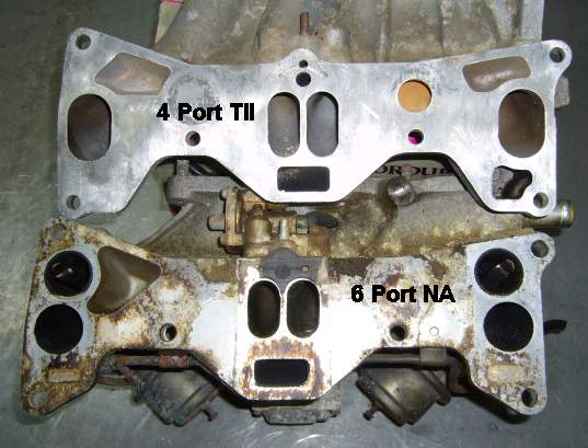
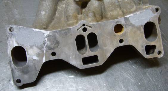
Now with all that out of the way, let's get to the point of this article. The image below shows the difference between the 4 port TII lower intake on the top, and the 6 port NA lower intake (in this case, from a GSL-SE 1st gen) on the bottom. While the ports appear to be in different locations, they actually "almost" line up. As well, all of the bolt holes are shared between both manifolds, so the 6 port manifold will bolt to the 4 port engine and vice versa.

Comparison between ports on 4 port TII lower intake and 6 port NA lower intake

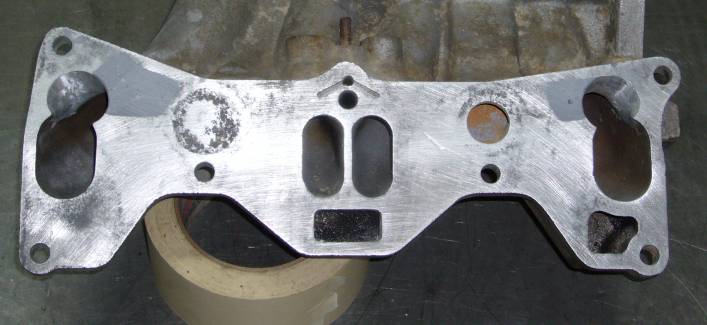
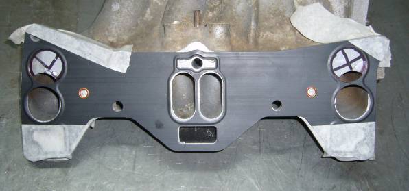
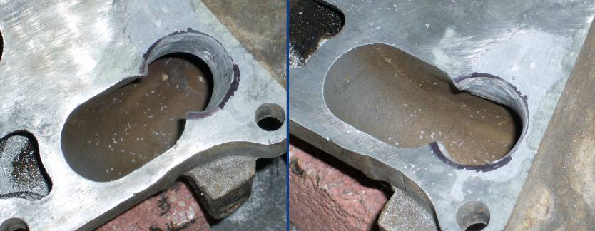
The idea is to make the secondary (end) ports on the TII lower look like the secondary and aux ports on the NA lower intake. To do this, the two cavities above the secondary ports on the TII lower intake will be filled with epoxy and then that area will be ground out to match the pattern of a 6 port NA lower intake manifold gasket.

Parts and Tools Required

Instructions

Step 1 - Prep The TII Lower Intake Manifold
Begin by prepping the TII lower intake manifold. Strip the manifold down by removing the ACV, EGR valve, sub zero valve and anything else that may be cluttering it up. You can discard/sell/crush/make furniture out of these three components because they will not be needed again. Thoroughly clean the manifold both internally and externally. A parts washer is the ideal way to accomplish this but if you don't have one, then a wash in warm water with a suitable degreaser (I prefer Castrol Super Clean) will do the job. Use carburetor cleaner to remove all the carbon deposits from the interior of the manifold. A Scotch-Brite pad will clean up the flange surface and a wire brush will remove all the gunk from the two cavities above the ports. This area must be very clean if we want the epoxy to adhere properly.
Step 2 - Prep The Cavities For Filling
The cavities above the secondary intake ports will be filled with epoxy but in order to get a solid bond, the area must be clean and the bare metal exposed. Both of these tasks can be accomplished at the same time by using a small grinding stone on the Dremel tool. Keep the speed low and grind out the entire cavity. You may need to use several different shapes of stones to do this and make sure to get into every corner. It doesn't really matter if you do some damage to the inside of the cavity as it will be filled with epoxy soon. Remember that you are not trying to smooth this area out, but simply remove all the encrusted filth and provide a "tooth" to which the epoxy will adhere.

Cleaning out the cavaties with a grinding stone

Once the grinding is finished, clean the entire manifold flange, cavities and runners with a residue free solvent such as brake cleaner. Thoroughly dry the area, preferably with an air compressor.

Step 3 - Fill The Cavities With Epoxy
One side at a time, mix up enough epoxy to fill each cavity and then simply pour it in. Go slowly and poke into the epoxy as you are filling the cavity to remove all the air bubbles. You can fill the entire area at once if you are careful not to trap any large air bubbles. I like to use a bit of welding wire to poke the epoxy as it is being added. This helps remove trapped air. Try not to get any epoxy onto the flange surface as you will just have to remove it later. If you are a bit clumsy with these sorts of things, use masking tape to cover the flange and then cut the cavity out with a razor blade.

Filling the manifold cavities with epoxy

It will take about a day for the epoxy to cure fully, or even longer if the temperature is low. Give it a few days just to make sure because the whole project will become a huge mess if you start grinding and hit a pocket of uncured epoxy.

Once the epoxy is fully dry, take out your sanding block and knock down most of the excess epoxy that might be higher then the flange. You don't need to make it perfectly flat, we will do that later.

Roughly sanded filler epoxy
Step 4 - Mark Your Ports
Lay the 6 port NA lower intake manifold gasket onto the flange and then line up the bolt holes. Tape it into place so it does not move around. Now, using a marker, trace the top aux port holes onto the manifold flange.

Using the 6 port gasket to mark area to be removed on 4 port manifold

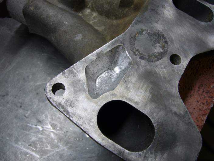
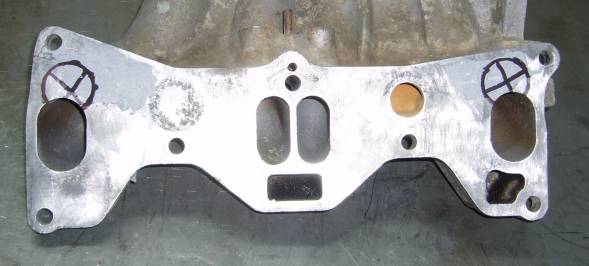
When the tape and gasket is removed, your manifold should have the area to be ground out clearly marked on the 4 port manifold.

Area to be ported out marked on manifold
Step 5 - Port The Right Side Of The Manifold Flange
Now the fun can begin! Using the rotary file attachment on your Dremel tool, begin porting the right side of the manifold. The rotary file is the best bit to use on soft aluminum castings, and it works quite well on the epoxy as well. But keep in mind that it will eat aluminum at a far slower rate then the epoxy, so you need to adjust your pressure when you move from one material to another. Don't bother with grinding stones here, they will just clog up in short time with aluminum. Try to find a medium speed on your tool that removes material quickly but does not clog up the bit with aluminum. On my Dremel, that speed is just before "3" on the dial, though yours is probably different. I like to alternate my pressure, pressing down until the Dremel starts to bog a little then lifting up to let the bit come back up to speed.

When starting the port, just concentrate on removing much of the material that is in the way. Rough out the port shape while moving a bit up and to the left, following the runner. There is actually quite a lot of material that can be removed from the left port wall to tie your new port into the runner. But don't go hog wild on the right wall as there is a thin casting there to make room for the bolt which secures the flange to the engine.

Beginning to port the right side of the manifold

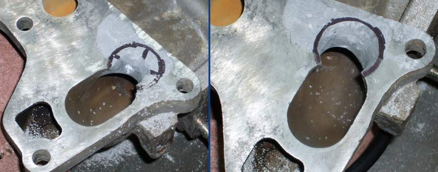
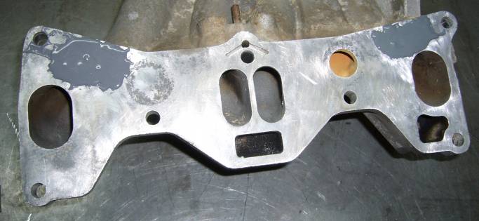
Once you have the basic port shape established, you can refine it. The left side of the port can be ground so that its wall matches up with the wall of the manifold runner. However the right side needs to taper out from the wall of the runner to avoid grinding through the casting around the bolt hole. The top of the port can be a very slight taper from the manifold runner outward. While you are porting, check the wall thickness between your fingers to make sure you aren't in the danger zone as every casting is a little different. There is quite a lot of material to remove where the manifold runner will meet your port. Spend a good amount of time smoothing that transition and make sure you are not creating any sharp lips where the runner meets the port.

Finalizing the port shapes

You can see from the pictures above how the walls on the left side of the port taper into the runner, while the walls on the right side of the port taper out from the runner. A good amount of time has been spent inside the runner where the camera cannot see to match the runner to the new port.

Step 6 - Port The Left Side Of The Manifold Flange
The left side of the manifold is essentially the same as the right side. On the left side of the port, the runner has to taper out into the port to avoid grinding through the bolt area. On the right side of the port, you can grind heavily so that the port tapers into the runner. The top can be almost flush as on the other side of the manifold.

Porting the left side of the manifold

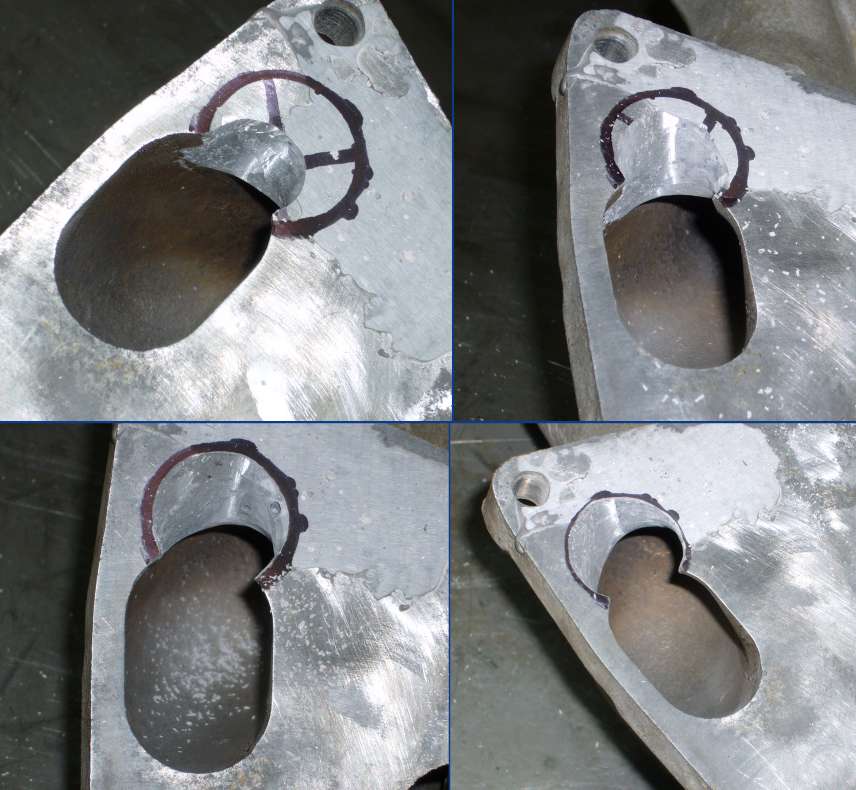
The last picture shows how you can go heavily into the runner. This is important for airflow. It is also very important that you keep the size of the ports the same on both sides of the runner. If there is a significant difference between the port sizes, airflow will not be the same through each one and you will end up with an uneven air/fuel ratio between the rotors.

Step 7 - Sand The Manifold Flange Flat
With your sanding block, sand the manifold until all excess epoxy is removed and the entire manifold flange is flat. Also use the sandpaper to lightly sand the insides of the runners as well as to take off the sharp lip where the new port meets the flange. Removing this sharp lip will prevent the epoxy from cracking.

Manifold finished, ported and sanded
Step 8 - You're Done!
The manifold is now complete. Make sure to blow out all the grinding dust and chunks of aluminum that have accumulated in the runners during the porting.

Notes

  1. A few words about gaskets: Both the NA and TII intake manifold gaskets will work when bolting this intake to a 6 port block. If you use the 6 port gasket, I suggest you use the S4 style paper gasket as opposed to the S5 style metal gasket. Then, trim the extra material that used to be between the aux and secondary port so that it does not flap around in the airstream and eventually make it's way into the engine. If you choose to use a TII intake manifold gasket, you will need to trim the gasket in the area we ported out.
  2. Depending on which engine you are bolting this manifold to, you may need to fill some more ports in either the engine block or the gasket itself. The bottom most ports on the manifold are EGR and air ports for the emissions system. Take a good look at both the engine block you are using as well as the gasket you have to determine which ports need to be filled in with epoxy.

Back To Mods Page | Mail Me | Search