| Home > RX-7 > Tech/Mods > Tech Info > Proper RX-7 Grounding Procedures |
| Home > RX-7 > Tech/Mods > Tech Info > Proper RX-7 Grounding Procedures |
There is a lot of misinformation out there regarding proper grounding procedures and fixes for the RX-7. Much of this is being spread by people with little to no knowledge of how the electrical system in these cars actually works. Many of these people describe the grounding system in the RX-7 as "poor", "sub-standard" or "flawed". The simple fact is that the grounds in the RX-7 are no worse then any car of the time period and that adding millions of extra grounds to the engine and chassis is going to have virtually no effect unless the root problem of damaged or dirty stock grounds is first taken care of. Here we'll cover what exactly a ground is, why it is important, why the typical grounding "fixes" do not work and how to deal with grounding problems properly.
Essentially, a "ground" is an electrical connection to a common return in circuit. In automotive terms a ground is a connection to the body or other metal surface of the vehicle. The body in the RX-7 is connected to the negative terminal of the battery. Thus any connection to the body of the car is a connection to the negative terminal of the battery. Electricity flows from the positive of the battery, through the circuit to do some work, then back through the body to the battery (technically electrons actually flow from negative to positive but that is beyond the scope of this article). This is a "negative ground" system which is by far the most popular automotive ground scheme used in the automotive world. "Positive ground" systems were popular in the beginning with all car manufacturers and continued on in British vehicles until recently.
The main reason this is done is to greatly simplify the wiring of a vehicle. Since most car bodies are made of metal (at the very least almost all frames are) they provide a perfect ground plane, eliminating the need to run a separate ground wire to each circuit which almost chops the amount of wire necessary in half.
Good grounds are important because poor grounds cause voltage drop. The consequence of this voltage drop is that the systems in that circuit can malfunction. How do bad grounds cause voltage drop? Well, the answer is Ohms Law.
Ohm's Law states that V=IR. This means that the voltage drop (V) is proportional to the current through the circuit (I) and the resistance (R) of the resistor (or bad ground in our case). An easy example is attempting to draw 10 amps through a bad ground with a resistance of 1 Ohm. So V=10(1) thus making the voltage drop a whopping 10V. This leaves only 2 volts available (in a standard automotive 12V system) to power the circuit and means that all that extra power must be dissipated as heat at the resistor (bad ground). Generally this heat makes the condition even worse, causing more voltage drop and more heat. In the most severe cases the ground will function under light loads yet fail under high current draws causing what appears to be an intermittent failure. Many people have seen this behavior caused by a loose (high resistance) battery terminal.
In a car with a relatively modern fuel injection like the RX-7, the chief problem associated with poor grounds is that sensor readings can be effected. All the sensors in the RX-7 are ground referenced meaning that the ECU passes a current through them to ground essentially measuring the voltage drop across the sensor and using it to adjust engine parameters. If another resistance if introduced into the circuit this value changes and thus the ECU sees the wrong sensor reading. The ECT (Engine Coolant Temperature) sensor/water thermo sensor, IAT (Air Intake Temperature) sensor, TPS (Throttle Position Sensor), pressure/boost sensor, atmospheric pressure sensor and AFM (Air Flow Meter) are all essentially variable resistors with the ECU on one side and a ground on the other (this is a great simplification but good enough for our purposes). The O2 sensor and knock sensor both generate their own voltages but are still connected to ground on one side with the other wire feeding the ECU through a shielded conductor. These sensor errors can cause all kinds of drivability problems that range from the common 3800 RPM hesitation, bucking on decel, poor performance or even sporadic CEL (Check Engine Light) illumination.
Aside from fuel injection issues, bad grounds can cause poor performance in almost any circuit. Voltage drop can manifest itself as dim headlights, one circuit malfunctioning when another is switched on (a common symptom is that the heater blow slows and dash lights dim when the brake pedal is pressed) and all kinds of other random weird issues.
There are many writeups dealing with regrounding the RX-7. What is unfortunate about most of them is that they completely ignore the important grounds and are far more interesting with adding random and pointless wires to the engine bay.
To understand this, you must know that there are four important ground connections on the RX-7. There are two main battery grounds where the battery connects to the chassis and engine, an ECU ground that connects the ECU to the top of the engine and another multiple chassis ground that serves many chassis and dash circuits. The exact locations of these will be covered below, for now it is just necessary to know that these grounds exist.
The typical RX-7 grounding writeup will basically consist of instructions to run a bunch of wires from the negative battery terminal to various spots on the car; some one the body, some on the engine, one to the alternator, one to the starter and a few others to various other miscellaneous locations. All of these wires neatly avoid actually correcting the problem areas with the possible exception of the connection from the battery negative to the engine (or starter/alternator). No one will debate that in a 20+ year old car the main battery grounding points can become corroded and running a new ground can be an improvement. Of course it would make far more sense to just fix the existing ground points instead of just running a bunch of extra wire. This leads into the real explanation of why this grounding "technique" is essentially pointless: it does not actually reground anything!
Think of it this way: the battery negative connects to the engine, the ECU grounds to the engine, so why do we want to run more grounds from the battery to engine when there is already a heavy stock ground in place? And more to the point, why do all these writeups ignore the ever important ECU ground? Connecting a mess of wires from the battery to the engine is not going to help if the connection between the ECU and engine is bad. Since the ECU ground is the most important single grounding point for the entire fuel injection system it's health is very important to the overall performance of the car.
This same concept applies to the rest of the system as well. Why run a ground to the alternator when it is already grounded to the engine by it's body? Why ground the ignition coils when they already ground to the body through the metal case of the igniter? Why bring another ground to the starter when the main battery ground already attaches via one of the starter mounting bolts? The simple answer is that all of this is unnecessary and likely came about because those doing these writeups are not well versed in electronic/electrical theory. While running a redundant ground to the engine block is never a bad idea, the line must be drawn somewhere which means you do not have to run multiple heavy gauge cable to various areas of the engine.
Finally, the actual method of assembling these ground cables can be put into question. It's a well known fact that crimp terminals are not reliable in the long term unless they are sealed with heat shrink and packed with dielectric grease. This means that in a few years (depending on driving conditions) your grounding "fix" can be in just as poor condition as the stock system, negating any benefit the "fix" provides. Many writeups specify that "high quality audio cable" be used due to it's oxygen free construction and thin wires. Oxygen free copper wire is wire that has been cast in a controlled non oxygen-reducing environment. The idea is that this special wire will not oxidize as fast as regular copper, and avoid brittle areas where heat (for example, from soldering) was applied. The real truth is that oxygen free copper wire will oxidize just as quickly as plain old copper wire and that a properly supported solder joint will not have with damage due to strain if properly sheathed and supported. Thin wires are often touted as having lower resistance since electrons travel on the outer edges of the wire (the "skin effect"). The theory is that due to the skin effect, having many tinner wires with a large surface area will mean a lower resistance cable. This sounds great, but the reality is that the skin effect is only valid in a high frequency AC circuit, and even then in order to take advantage of many thin wires each wire must be individually insulated from each other. This is referred to as a "Litz Conductor". In a DC application like an automotive system, it is the total cross section of the conductor that determines current carrying capability and voltage drop. Thin wires do certainly make the cable easier to handle though.
So now that we know how to do it wrong, let's take a look at how to do it right.
If we want to properly reground the RX-7, we must first start by taking care of the existing grounds, adding only under rare circumstances when the factory ground is too badly damaged. The idea is to clean the ground terminals, bolts and surrounding area and then to reassemble using the appropriate anti-seize compounds and dielectric grease. The same basic steps apply to almost all the ground connections but we will cover each one individually.
Please read the entire instructions before you start to make sure you have the correct parts on hand. A parts list is not given since what is required can vary significantly with each job.
The main battery ground is the most important ground on the car. Without it, the battery has no connection to the engine or chassis. If it becomes intermittent due to loose fasteners or corrosion the resultant problems can include hard starting, slow cranking speeds, undercharged batteries and many other strange electrical phenomena.
The battery grounds in two locations; at the driver shock tower and at the starter. The shock tower ground is secured with a M6x1.0 bolt directly into the inner sheet metal of the shock tower. The starter ground is connected to the starter mounting bolt that passes through the bellhousing of the transmission. The shock tower ground is highlighted in the picture below. Thanks to buttsjim on the RX-7 Forum for the image.
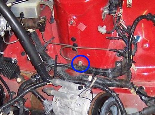
The problem with this location is that the mounting bolt protrudes into the wheel well area and is thus subject to dirt, water and salt thrown up by the wheel. This gunk gets worked into the threads and corrodes the connection. The lug itself is crimped directly onto the ground wire.
To clean this connection, first remove the M6 bolt and then throw it away. Pull the wiring harness slightly away from the shock tower so you can access the lug. Space is tight if the car is equipped with power steering and/or air conditioning so it may take some creative positioning to gain access. Spray the entire area down with brake cleaner to remove excess grease and dirt. If the lug on the harness is not too badly corroded, it can be cleaned up with a stiff bristle wire brush or fine grit sandpaper. Clean it until the copper shines. Next, clean the threads in the car. Use an M6x1.0 tap or thread chaser to clean the threads. If you use a tap be careful not to damage them. Clean the area around the hole with sand paper or a wire brush, removing all the rust and paint so that shiny bare metal is visible. Coat a new stainless steel M6x1.0 bolt with dielectric grease thoroughly. After covering the exposed ground cable and lug in a thick coat of dielectric grease, use the bolt to reconnect the lug to the shock tower.
The same technique is used to clean the starter ground. Remove the bolt and disconnect the lug, then clean it thoroughly. Clean the bolt with a wire wheel and clean the surrounding area on the starter and bellhousing. Cover everything in dielectric grease and then reassemble, making sure to torque the bolt to 27-38 Ft-lbs (for '86-'88) or 37-52 Ft-lbs (for '89-'92).
If either of these lugs or the cable is damaged or corroded past what a simple cleaning can do, then the cable must be replaced. Most of the auto parts stores sell 4 AWG and 2 AWG ground cables of varying lengths that are suitable for this kind of repair. If you must replace the section that leads from the battery to the shock tower, make sure to get a cable of sufficient length with a eyelet terminal on one end (for connection to the shock tower) and a battery lug on the other (for connection to the battery). These pre-made cables are assembled as one piece with the terminals cast directly onto the cable. Thus it is difficult for moisture to penetrate and the cable will last quite a while. As with any electrical connection, the cable ends should be covered in dielectric grease to help prevent corrosion. If you need to replace the section of cable that leads from the shock tower to the starter, then a similar cable with two eyelet lugs on each end can be purchased.
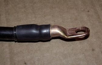
Custom cables can also be made should the local auto parts store not have a suitable length. Welding stores carry an assortment of cable and terminals that are of higher quality then most automotive stores have in stock. 4 AWG cable is generally thick enough though 2 AWG can be used as well. Anything larger is just more weight. For terminals, you will want to purchase copper/brass solder terminals and NOT the hammer-on type. To construct the cable you will strip about 1/2" of insulation off of the cable and then insert it into the lug. Clamp the lug by the eyelet section in a vice with the cable pointing up and then use a propane torch to evenly heat the lug while applying a rosin core solder to the connection. Once things are hot enough the solder will easily melt and flow into the terminal, wicking slightly up the cable. Continue until the solder overflows and the connection is solid. It will take a surprisingly large amount of solder. Once the connection has cooled, scrape away all the excess flux and then pack the area with dielectric grease. Now use an inch or two of large adhesive lined heat shrink to seal the connection. Repeat as necessary. You should end up with something like what is pictured below:
To connect this to a battery terminal, use lugs that are designed for connection to an eyelet terminal. They generally come with a stud that is embedded into the lead with a wing nut on top. Remember your dielectric grease. Avoid the clamp on battery lugs as they are designed for temporary use and are not reliable in the long term.
The ECU ground is the most important ground relating to the performance of the car. Almost the entire fuel injection system grounds through this point with the exception of the O2 sensor and ignition coils. If this ground is poor, then all manner of weirdness can result including the infamous 3800 RPM hesitation. Because this ground is so difficult to access (it is located under the upper intake) it is often ignored and left to corrode.
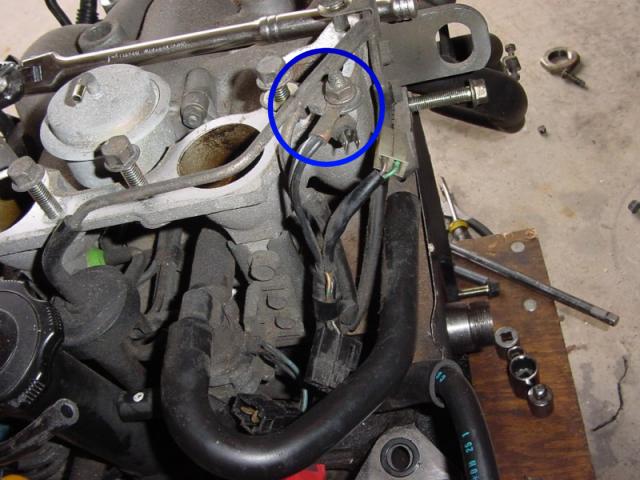
The exact location of this ground varies with the model of car. S4 NAs and most TIIs have it on the solenoid rack under the intake near the BAC valve (drivers side, near oil filler neck) as shown in the image (S4 NA shown):
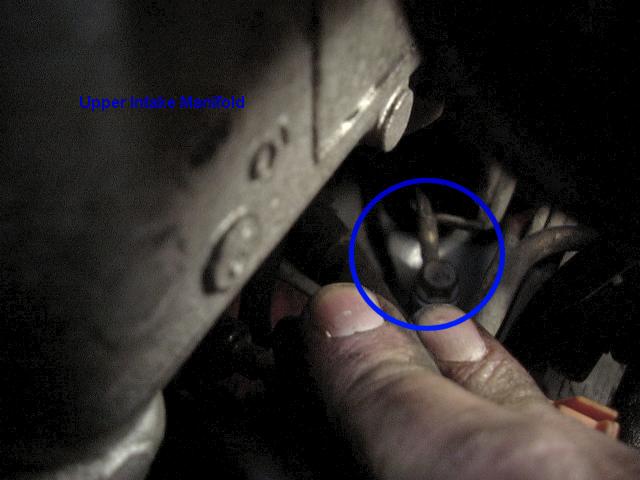
With the upper intake removed, you can clearly see the ECU ground on an S4 NA:
On the S5 NAs and some TIIs, the ECU ground can generally be found on the upper intake (image courtesy of NeCr0mStR from the RX-7 Forum, S5 NA shown):
Additionally, these grounds can "move around" a little over the years due to service. Their exact location is unimportant as long as they are bolted solidly to the engine. If you have trouble locating this ground, just look for the copper ring terminal with two black wires attached.
In order to access this ground you generally have to remove the upper intake manifold. Removal procedures for this manifold are covered in the Factory Service and Haynes manuals. With the manifold out of the way you can loosen the bolt and detach the ground from the engine block. Throw away the bolt or nut and use a stainless replacement. The size is either M6 x 1.0 or M8 x 1.25 depending on where the ground was located. Because the crimp connection is likely in poor condition, cut off the ringe terminal. Strip some insulation from the ends of each wire and examine the condition of the wire. Some tarnishing is normal but if you find powdery green or white corrosion you will need to cut out the damaged sections and replace them. Because this wire disappears into the harness it may be a lot easier to simply run new ground wires from the ECU if you find yourself chopping off large sections of this wire. If that is the case, use 12AWG automotive grade copper wire as a replacement. You can find the wires at the ECU as part of the emissions harness. They are the two thick black wires connected to pins 3G and 3A (all years). Cut the wires at the ECU, leaving enough room to attach your new wires. Do this by soldering and then covering with adhesive lined heat shrink tubing. Run your new wires up through the grommet into the engine bay, along the harness and then to the ground location.
Whether you are attaching a new terminal to the existing wires or to new ground wires you ran from the ECU it is important to use the appropriate terminals and a proper crimping tool. Pliers or ViceGrips are not acceptable crimping tools. If you can find them, you will want to use heat sealable ring terminals. Most electronics stores will either stock them or can order them easily. They differ from regular ring terminals in that after you crimp them you then heat-shrink the built in jacket around the wire to form a weather tight seal. If you cannot locate these terminals, regular crimp terminals and adhesive lined heatshrink tubing makes an acceptable substitute. Regardless of the type of terminal you use, pack it with dielectric grease and use one terminal for each wire instead of combining them like the factory did (redundancy).
To attach this new ground you must first clean the area on the engine it will be secured to. Chase the threads with a tap or thread chaser and then use a wire brush to thoroughly clean surrounding metal. Apply a coating of dielectric grease to the bolt threads, engine and terminal and then secure everything in place. Now take a nice big wad of dielectric grease and slather the entire connecting in a thick layer.
Once you are done servicing the ground, you can reinstall the upper intake. This is also a good time to replace any cracked vacuum hose, check the condition of fuel lines and metering oil lines, and inspect the rest of the electrical connectors. Make sure to use anti-seize on all bolts and use a new gasket on reassembly.
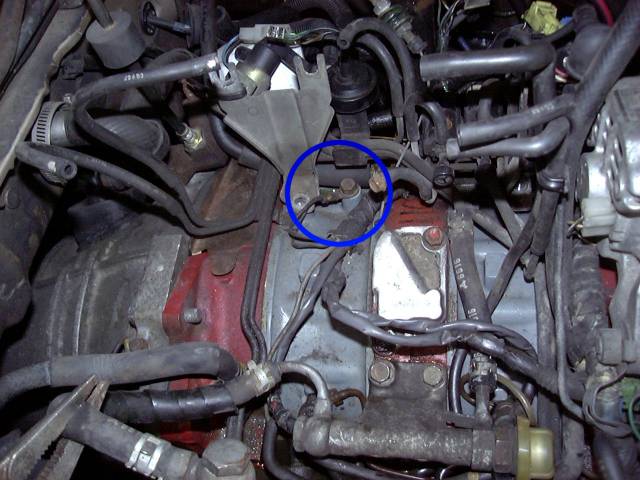
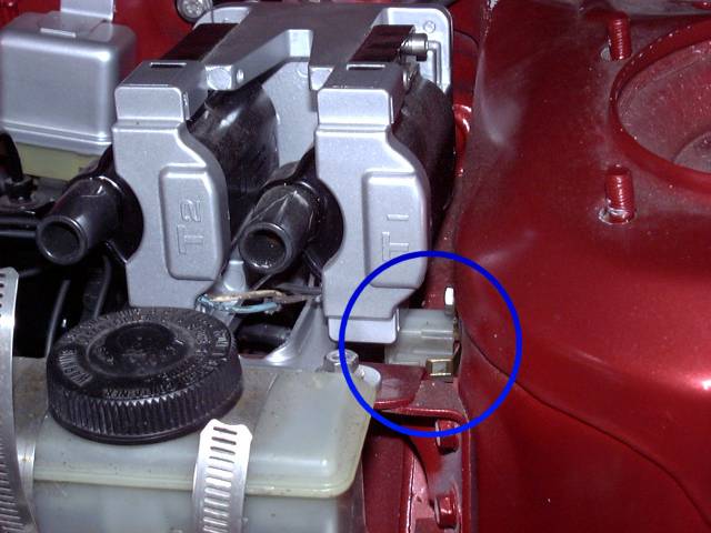
This is a ground that almost none of the other grounding writeups even mentions. If you look directly at the top of the drivers shock tower near the area where the trailing coil is mounted you should find a white connector seemingly plugged into nowhere on the inner side of the tower. Leading to this connector is a thick bundle of black ground wires. This connection grounds systems throughout the car yet is often overlooked because most don't even know it exists. Repairing this ground is simple can cure multiple issues (particularly with in-dash circuits).
This image shows the ground connector between the trailing coil and shock tower:
To access this ground you will probably want to remove the trailing ignition coil for space. With the trailing coil out of the way, the connector can be disconnected. Now you will see that the connector plugs into a large copper grounding block covered in spade connectors. That block is held onto the shock tower by a single M6x1.0 bolt. Remove that bolt and then remove the ground block.
The block is made of copper and can thus be easily cleaned on a wire wheel mounted on a drill or grinder. Do be careful since more then once I have experienced the wire wheel catching on the block and flinging it towards my face. Generally this is not fun. Once the bock is shiny, set it aside and turn your attention to the car. Chase the threads in the shock tower with a tap and clean the area around the hole down to bare metal with a wire brush.
Contact cleaner is the preferred method of cleaning the harness connection but be aware that some contact cleaners destroy plastic. Make sure to read the instructions. Liberally soak the connectors in cleaner and then blow dry after 30 seconds or so. Repeat this several times in about 10 minutes to try and dissolve all the crud and corrosion. Contact cleaner is nasty stuff so keep it out of your eyes when you blow off the connector. Most of the time the wiring here is in good shape so all that's required is a cleaning. If you have damaged connections then the offending spade will need to be pulled out of the connector, recrimped and reinserted. Lacking the special crimper required, you may simply want to separate the damaged wire from the harness and secure to the ground block mounting bolt with a ring terminal.
Now that everything is clean, you can reassemble the ground. Coat a new stainless steel M6x1.0 bolt liberally with dielectric grease. Cover the copper ground block with the same grease and use the bolt to secure the ground block to the shock tower. Make sure that plenty of grease got between the block and tower. Squeeze grease into every contact on the harness, packing it in tightly with your finger. Reconnect the harness and make sure it is latched on tightly.
Reinstall the trailing coil if you removed it. Remember to use anti-seize on the bolts, and dielectric grease on all connectors (especially the plug wire boots).
On the passenger side of the engine at the firewall, there is a black wire leading from the transmission bellhousing to the firewall. Clean the terminal at each end as described above, cover with dielectric grease and reassemble using a new stainless M6x1.0 bolt to secure it to the bellhousing. Don't forget the anti-seize which must be used when mating a stainless fastener and aluminum.
There is a semi-ground that can usually be found on the slave cylinder mounting bolt closest to the drivers side. This is a capacitor to filter the signal to the oil pressure gauge. It connects to a single spade style connector on the yellow/red wire found on the engine harness. While not super critical, strange behavior on the oil pressure gauge can result if it is disconnected. These like to disappear after a transmission or clutch job so don't be surprised if yours is gone. This ground is serviced as described above. Clean the contacts, cover with dielectric grease on both ends and reinstall with clean hardware.
You will also find grounds located all over the car. At the back, there are grounds for the taillights and fuel filler neck. At the front, grounds for the lights can be found at the nose of the car. And many other grounding points are in between. In general, the interior grounding points are almost never a problem since they are not exposed to the weather. However, anytime you come across a ground point it is probably a good idea to put in the minimal effort to clean it up and protect it with dielectric grease to help avoid issues in the future. Since so many circuits in the RX-7 are switched-negative this can help avoid weird problems.
With a little understanding of how the ground system works, and a little labor to clean it up, many common problems with the RX-7 can be solved. And all this is accomplished without spending money on fancy grounding kits or introducing bundles of extra wires into the engine compartment. Properly serviced grounds will be reliable for years to come and require minimal attention in the future.
Back To Tech Page | Mail Me | Search | ![]()