| Home > RX-7 > Tech/Mods > Modifications > Extreme S4 Wastegate Porting |
| Home > RX-7 > Tech/Mods > Modifications > Extreme S4 Wastegate Porting |
This article originally appeared in Volume 2, Issue 2 of RXTuner. The article is meant as a "how to" covering the popular technique of severely porting the wastegate orifice and welding on a larger flapper door. I did not develop this procedure; it has been in use for many years.
Boost creep and overboost; two phrases which should strike fear into the hearts of S4 (and to a lesser extent, S5) Turbo II owners. Simply put, boost creep is the gradual increase in boost pressure while the car is under constant boost. Overboost happens when the boost pressure generated by the turbocharger is much more then expected. The result is a dangerous level of boost, which damage or blow the engine if the fuel system is inadequate.
Both problems are caused by the pathetically small wastegate used on the Series 4 turbocharger. This wastegate is roughly 16MM in diameter and simply unable to bypass enough exhaust gas past the turbine once the car has been upgraded with a more free flowing exhaust and intake. Indeed, boost creep has been observed even on totally stock cars under the right circumstances. Why such a small wastegate was used by Mazda is a little bit of a mystery, because even vehicles with much smaller turbochargers will employ wastegates twice as large as the Hitachi turbo used in the RX-7. Regardless, this problem is an easy one to cure. The solution is to port out the wastegate, thus radically increasing it's flow.
This article covers the process of porting the wastegate orifice well past stock sizes, and then installing a larger flapper door to properly cover the newly enlarged port. The result is a much finer control over boost pressure, while still maintaining proper turbocharger response.
The tools you will need are as follows:
Removal of the wastegate actuator is the first step. Simply remove the "E" clip that holds the rod to the flapper lever and then slide off the actuator rod. After disconnecting the vacuum line to the actuator diaphragm and removing the two 13MM bolts that secure it to the compressor housing, the actuator can be separated from the turbocharger.
The turbine housing is a very close tolerance fit to the center section. To remove it, you must first remove the 6 bolts that clamp it in place. This is best accomplished by placing the turbocharger into a vice, placing the 13MM box wrench onto each bolt and tapping the wrench with the sledge/mallet. It may take some effort, but eventually they will break free. To get at the bolts that are blocked by the oil fittings, you need to rotate the exhaust housing in place. It may take some hammer blows to break it free, and the fit even when free is very tight. A few shots of penetrating oil helps things slide. As the turbine housing comes free, sit the turbocharger vertically with the compressor housing on top. Have a helper hold it in place and slowly lift it up while you loosen and remove the bolts. Set the rest of the turbocharger aside, being careful not to damage the turbine wheel.
Now, simply remove the two 13MM bolts on the back plate, and pull it off of the turbine housing. A light tap with the hammer may be required.
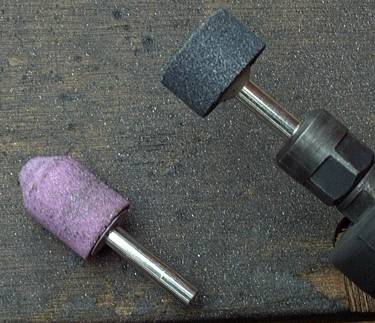
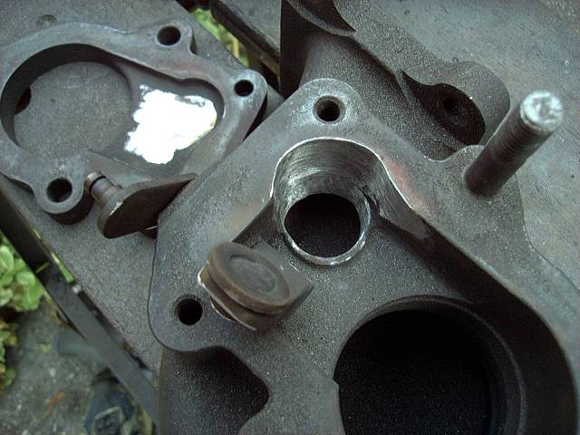
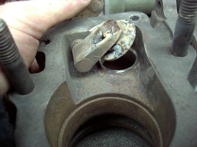
First, we need to roughly enlarge the existing port. I have found that the quickest and easiest way is to use a cone shaped grinding stone, and hold the die grinder vertically in the hole. Allow the lower face of the stone to do the work, applying enough pressure to cut the material, yet not enough to bind up the grinder. It should only take a few minutes to cut cleanly through. It goes without saying that safety glasses (or even better, a face shield) and earplugs are to be worn. As you can see from the image, that initial hole is a little rough, but we will clean it up later. The excess material on the radius of the wall near the port has also been ground away, creating a smoother path for exhaust gasses. In addition, a relief has been cut into the back plate, allowing the arm to swing up slightly higher to compensate for the thicker flapper door we will install.
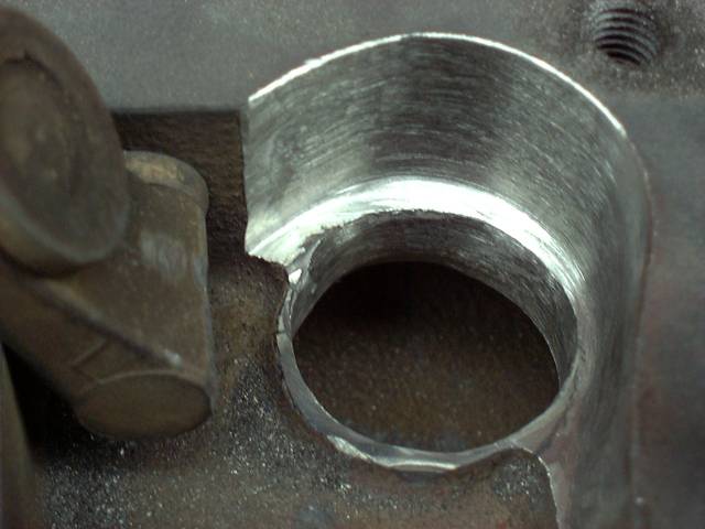
With the rough cut done, concentrate on enlarging the orifice while keeping it round. Do this with the cone shaped stone and try to taper the hole wider toward the runner. This will encourage flow to the wastegate. You can increase the side of the port quite large, to a little smaller then 40MM. At some point, you will need to begin cutting into the wall of the turbine housing. Switch to the cylindrical shaped stone and begin to grind away the wall, forming a ridge around the wastegate orifice. Continue alternately increasing the size of the hole and removing material from the wall until you end up with a port similar to what you see in figure 3. Notice the seating area left for the wastegate flapper to seal against, and the relief cuts made in the wall of the housing.
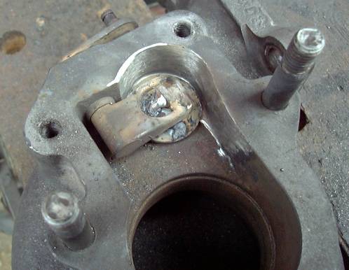
This new door can be made of many materials. Piston engine valve heads work well (and are a great irony), but any suitably thick (3MM roughly) washer will do the job. Shown in figure 5 is a large flat washer positioned to completely cover the new orifice. Some clearance will have to be left around the edges, or the door will jam as it pivots. In this case, one washer was too thin, so two washers were welded together. Regardless of the material you choose, you should have a few millimeters of "buffer area" around the edges of the flapper, to provide a sealing surface. An absolute seal is not critical, but that doesn't mean it should be sloppy.
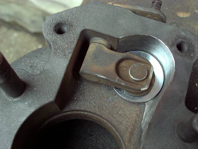
Now, clamp the washers in place, and make a tack weld. Check the action of the flapper door by running it through it's motion several times, and then finish weld it in place. It is also important to prevent the new assembly from pivoting side to side. As you can see, the stock flapper is on a bit of a wobble. While this works well in a stock application and provides some play to form a good seal, our larger flapper will now jam if this motion is allowed to continue. Make a weld on the top of the flapper arm to secure the flapper door in a position that allows interference free movement throughout its range.
The images below show the finished product. You can now clean up your welds, and prepare for reassembly of the turbo.
Place the turbine housing in a vice, with the center section mating surface facing up. Have a helper lower the center section into the turbine housing, while you position the bolts and the "C" shaped clamps. Because of the location of the oil inlet and outlet flanges, the center section will have to be rotated while the bolts are tightened down. Tighten in several steps, first snugging to the point where you can still rotate the center section. Now, line up the corner of the oil outlet flange with the bolt closest to the raised lettering near the exhaust flange. With the turbocharger lined up, thoroughly tighten the bolts in 3 steps. It helps to use the mallet on the box end wrench as a makeshift impact driver. After the turbocharger is assembled, spin the wheels and make sure they turn smoothly. If they don't, then the alignment is off and you need to disassemble and reassemble. Tolerances are very close, so it may take a few tries. Anti-seize should be used on all bolts.
Now reinstall the wastegate diaphragm/actuator, and use a new E clip to attach it to the flapper arm. The final step is to reinstall the back plate of the turbine housing, using anti seize of course.
Porting the wastegate is an important modification in the category of safety. While it will not increase the power made by the engine, it will give you finer control over your boost level, and prevent possible (and expensive) engine damage. In my mind, it is a required mod for all those upgrading cars equipped with the stock S4 turbocharger. And since the cost is nearly free, there is no excuse for driving around on a turbo with a stock wastegate.
Back To Mods Page | Mail Me | Search | ![]()