Queries on DC to AC circuit using 555 timer
Printed from: Aaron's Homepage Forum
Topic URL: http://www.aaroncake.net/forum/topic.asp?TOPIC_ID=7123
Printed on: Jul 22 2026
Topic:
Topic author: liang2408
Subject: Queries on DC to AC circuit using 555 timer
Posted on: Feb 03 2008 06:57:20 AM
Message:
Hi Sir,
I have try to build a DC to AC inverter using 555 timer and a transformer that is 9-0-9V/230V and rated at 36VA. I managed to drive a light bulb of 11W. The attached file shows the schematics drawing of the inverter.
But when i didn't connect to any load and measured the input and output of the transformer, i got an input of 4.98Vrms on the primary side and 122Vrms on the secondary side. The output voltage is far below my requirement of 230VAC.
I hope you can give me some advises on the circuit and show me which part of the circuit to modify so as to achieve the desired output of 230VAC without any load connected. (Maybe i can use a center tap to boost up my input circuit.)
Sorry for your time and really appreciated for your help. Many thanks.
Download Attachment: 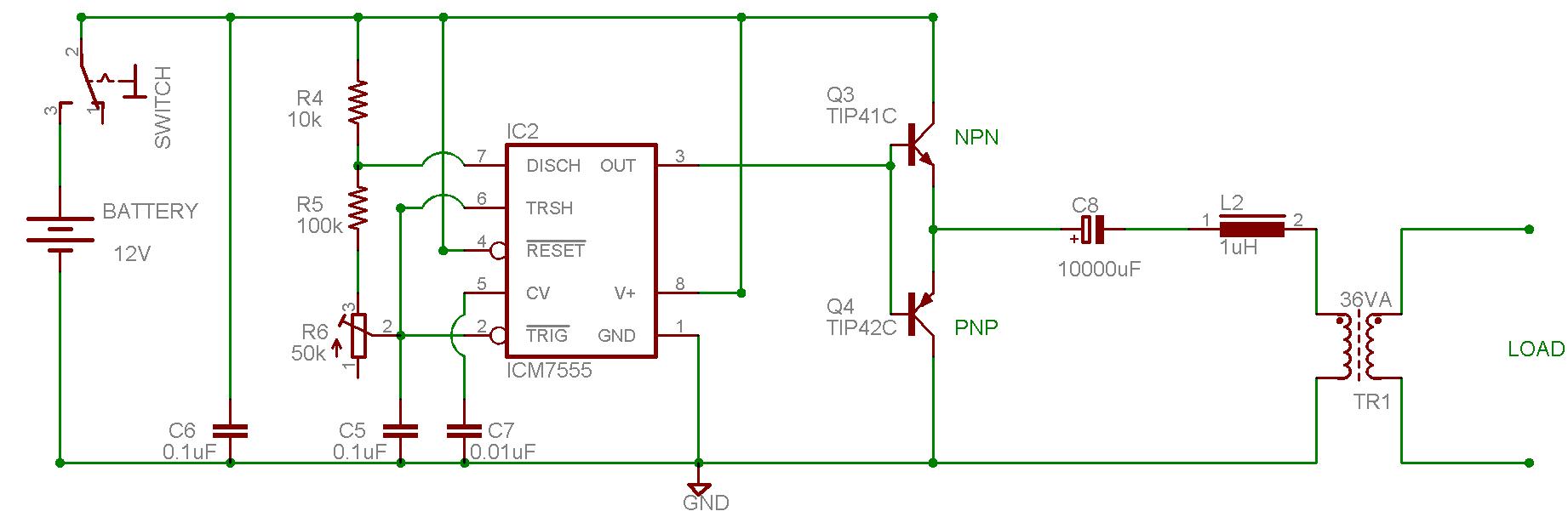 DC to AC Inverter.JPG
85.25 KB
Replies:
Reply author: audioguru
Replied on: Feb 03 2008 10:46:36 AM
Message:
Look at the datasheet for the 555 and of the transistors.
With a 12V supply, the output high voltage of a 555 without a load is +10.6V and is only +9.5V when fully loaded.
The output low voltage is 0.1V without a load and is +2.5V when fully loaded. So its output is only 7V p-p when fully loaded.
The transistors each have a loss of 0.7V without a load and a loss of up to 1V each with a load of 3A.
The output coupling capacitor has an internal resistance that causes a voltage loss when loaded and the choke also has a voltage loss.
The unloaded voltage feeding the transformer is 9.1V p-p which is 3.2V RMS.
Fully loaded, the voltage feeding the transformer is less than 1.8V RMS.
An ordinary multimeter has a huge error when reading the square-wave since it is calibrated for a sine-wave.
Reply author: mrgone
Replied on: Feb 03 2008 10:49:26 AM
Message:
There are a few thimgs that can go wrong. I don't know much about the ICM555 but are sure it has enough drive? What frequency is it producing? Those are good transistors you are using. Plenty of power for a light bulb & more but the configuration is horrible! The transformer should be feeding the collectors through a center tap and the emitters go to ground. Go search some PUSH-PULL amplifier circuits and you will see what I mean and if this is an attempt at a push-pull, you will also have to invert the 555 output so that you have two drives on the bases of both transistors. One in phase and out out of phase, or 180 degrees from each other.
Reply author: liang2408
Replied on: Feb 04 2008 01:12:41 AM
Message:
Hi,
Thanks for the reply. That circuit is not a purely a square wave as the presence of inductor and capacitor act as a filter.
The frequency that i generated from the 555 timer is 50Hz but it can only takes in +5V to +15V. Now mine concerned is that how am i able to produce a 230Vrms output without any load connected at the output of transformer. I hope that you are able to guide me on that schematics drawing on which part and how to modify it.
As i was thinking whether can i change my rating of my transformer or can i modify the circuit in such that it will function as centre tapped transformer. However, I do not know how to do it.
Regarding about the reply on the push-pull part, if i do that then where should i connect my inductor and capacitor?
Many Thanks
Reply author: mrgone
Replied on: Feb 04 2008 09:07:29 AM
Message:
Well, did you look up any push-pull amps? You will know how to make it I think. I would raise my frequency up to about 50KHz but get amplifier right first. Also did you understand that the signal from your '555 must also have another signal 180 out of phase with it (two signals). If you don't use push-pull then you only need one transistor or you can parallel two of them but not like that. Let me find some examples.
OK I found one & modified a quick work up on other. The "Single example" has a square wave oscillator I left in to give you an idea of optimal frequency.
Download Attachment:  Push-Pull example.GIF
4.2 KB
Download Attachment:  Single example.GIF
6.03 KB
Reply author: liang2408
Replied on: Feb 04 2008 10:55:11 AM
Message:
Hi,
First of all i would like to thanks you for your advices. From your reply, i do understand what you mean. But for my circuit that i posted, i am using npn and pnp transistor and a dc capacitor. From my understanding, the dc capacitor will charge and discharge and thus able to make signal alternating. But it is just that the output is not able to get 230VRMS. Maybe it is what audioguru had stated about the losses.
If i need to use centre tapped tranformer, i need to use 2 same npn transistors and not npn with pnp. Hence, i assume that my circuit are not able to modify to be able to get the required output voltage.
Do you have any circuit that is workable to produced 230VRMS from 12VDC with an operating frequency of 50Hz? Could you kindly post it for me cause i need one badly.
Thank you for your time.
Reply author: audioguru
Replied on: Feb 04 2008 11:30:38 AM
Message:
The tiny 1uH inductor won't filter a 50Hz square-wave. Its inductance must be 10,000 times more to round the corners a little. Then it will have such a high resistance that you won't get any power output.
I see additional losses in your circuit.
You don't have a 555 that has an output current of 200mA. You have an ICM7555 which is a low current Cmos 555 that has an output current of only a few milli-amps with a high voltage loss. The TIP41 and TIP42 transistors need a base current of hundreds of milli-amps to switch 3A to produce 36VA.
There are hundreds of inverter circuits on the internet. Some work and others don't. I have posted a few that work in this forum.
A CD4047 is an oscillator IC that uses one resistor and one capacitor. It has two opposing square-wave outputs to drive two Mosfets that drive a center-tapped transformer. A Cmos gate IC can be added for the circuit to make a modified sine-wave.
Reply author: mrgone
Replied on: Feb 04 2008 12:47:14 PM
Message:
Good Point! I would use MOSFETs. They tend to work better in this type of circuit don't they Guru? I think it has something to do with there tendancy toward non-linearity, so they are apt to produce more energy at various harmonics & spurious emittions.
Reply author: audioguru
Replied on: Feb 04 2008 2:46:52 PM
Message:
A Mosfet like an IRFZ44 (there are better ones)can conduct 35A with voltage loss of less than 1V.
A power transistor like a 2N3055 can conduct a current of only 10A with a massive 3.3A of base current and could have a voltage loss of 3V.
Reply author: liang2408
Replied on: Feb 04 2008 9:32:18 PM
Message:
Hi audioguru,
I have decided to build the circuit with CD4047 together with CD4001 and IRFZ44. Hopefully, it i will be able to get the voltage and waveform that was required.
Just to clarify something, the resistor value that was input to CD4047, can i use a potentiometer instead of fixed value so as i can adjust the frequency accordingly? Furthermore, can i used a 9-0-9/230 with a rated of 36VA instead of 10-0-10/230 transformer. What will be the difference and if not, can i use a 12-0-12/230 transformer? Lastly, there is a capacitor that is connected in series to a resistor of 100/5W. What is the value of the capacitor, is it 220uF and also is it a AC or DC capacitor?
Anyway, thanks for your kindly response.
Download Attachment: 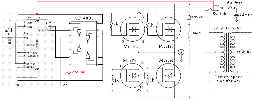 20081910308_Modified sine-wave inverter schematic.png
109.42 KB
Reply author: audioguru
Replied on: Feb 04 2008 11:43:03 PM
Message:
quote:
Originally posted by liang2408
Just to clarify something, the resistor value that was input to CD4047, can i use a potentiometer instead of fixed value so as i can adjust the frequency accordingly?
You can use a trimpot in series with a fixed resistor. A total of 47k will produce 50Hz and 39k will produce 60Hz.
quote:
Furthermore, can i used a 9-0-9/230 with a rated of 36VA instead of 10-0-10/230 transformer. What will be the difference and if not, can i use a 12-0-12/230 transformer?
A 36VA transformer is tiny for an inverter. It might be made with a cheating turns ratio to make up for a low output voltage when it is used for a step-down transformer. Then when it is reversed its output voltage will be too low. if you use a 12V-0V-12v transformer then the modified sine-wave voltage will be too much to low.
quote:
Lastly, there is a capacitor that is connected in series to a resistor of 100/5W. What is the value of the capacitor, is it 220uF and also is it a AC or DC capacitor?
The capacitor must be non-polarized and is 220nF which is 0.22uF.
The 12V feeding the ICs should have a 100 ohm resistor in series and a 16V zener diode to ground at the ICs.
Reply author: liang2408
Replied on: Feb 05 2008 08:22:25 AM
Message:
Hi audioguru,
you mention that the 12V feeding the ICs should have a 100ohm resistor in series and a 16V zener diode to ground at the ICs. I managed to find a schematic diagram which is attached below. Is it the same connection that you mention for the zener diode and resistor?
if yes, but the diagram uses 47ohm as a resistor and not 100ohm so which one do i use? According to the electronic forum, i had read that there were 2 capacitors required for non-polarities. But according to the diagram, only the 220nF capacitor is required for the AC part but not for the 0.1uF capacitor which must have polarities.
Based on the diagram below, can i use 2 capacitors with a value of 0.1uF with polarities?
Lastly, is the diagram below shows the finalized diagram of the DC to AC inverter?
Download Attachment: 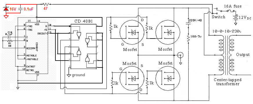 Inverter.PNG
109.4 KB
Reply author: mrgone
Replied on: Feb 05 2008 08:37:18 AM
Message:
Man, that looks alot better! No, don't use polarized caps. They will explode.
Reply author: audioguru
Replied on: Feb 05 2008 11:45:00 AM
Message:
The schematic shows 4 Mosfets but a very low current fuse. Only 2 IRFZ44 Mosfets are good for an output up to about 400W. Then the fuse should be 40A.
A 47 ohm resistor feeding a 16V zener diode or a 100 ohm resistor doesn't make any difference.
I think Dennis made this circuit.
Reply author: liang2408
Replied on: Feb 05 2008 8:04:06 PM
Message:
Thank you audioguru and mrgone for your advises. I will build that circuit based on that schematics and hopefully it works. I will update you all the results.
Thank you
Reply author: liang2408
Replied on: Feb 15 2008 10:08:59 AM
Message:
Hi audioguru,
I have patched up the circuit and tested it. I obtained a constant DC output for the cd4047 at pin 13 instead of a square waveform(Clock pulse). But i managed to get a square waveform at the pin 10 and 11 which both are inverted of one another at a frequency of 50Hz. I had changed a new cd4047 IC chip but the results are the same, do you know what are the reasons behind it?
Thank you for your precious time.
Reply author: audioguru
Replied on: Feb 15 2008 11:31:15 AM
Message:
Pin 13 of the CD4047 is supposed to be a square-wave at 100Hz. It feeds two gates of the CD4001. Maybe the two pins of the CD4001 are shorted to something.
Reply author: liang2408
Replied on: Feb 16 2008 07:05:49 AM
Message:
Thanks audioguru, well i had troubleshooted the circuit many times but the configurations was correct. Anyway, i will check and update you again.
By the way, are all ground pins of the cd4047, cd4001 and Mosfet ground at the same point meaning that isolation are not required???
Thanks
Reply author: audioguru
Replied on: Feb 16 2008 09:19:19 AM
Message:
The ground points of the entire circuit must be connected together or the circuit will not work.
Reply author: pearltorto
Replied on: Feb 17 2008 5:09:11 PM
Message:
say liang you wouldn't know a dr aziz?
Reply author: liang2408
Replied on: Feb 18 2008 01:50:58 AM
Message:
Hi pearltorto,
I do not know anyone of name dr aziz.
Reply author: liang2408
Replied on: Feb 18 2008 02:00:58 AM
Message:
Hi audioguru,
I had managed to troubleshoot the circuit and for the cd4047 and MC14001BCP is used to replace cd4001 are both functioning properly. I power this circuit up via a DC power supply of 12V, but the moment when i power up, the DC supply jumps to 20.8V and drawing a current of 0.6A. I did not turn on my load at all. Then I tried to measured the output of the transformer. The output frequency showed a value of 73Hz and a jump to 236Hz. The output frequency of cd4047(pin 11 and pin 10) are both 50Hz. Also the output RMS voltage is 367VRMS. I am using a 9-0-9/230VAC rated of 36VA transformer. Why is it so?
If i switch on a light bulb that consume 11W rated at 230VAC, will the output of the transformer drops to 230VAC or will my load explode.
Pls help me out in this. Thank you
Reply author: liang2408
Replied on: Feb 19 2008 01:50:51 AM
Message:
Hi Master audioguru,
r u there??? i have another questions that is will the type of capacitors used affect the frequency of the output of the transformer despite having the same capacitance value? For my case, i am using polyester instead of ceramics capacitors and does it explain why i will obtain oscillating output frequnecy?
As for the raise in the DC supply of 20.8V, is it due to the transformer tat causes it to increase and if it is, then if i connect my battery as input source, what will happen??
Pardon me for asking all these fundamental questions... I am desperate for help. Anyway, i really appreciate your reply. THANK YOU!!!
Reply author: ruaconbeou
Replied on: Mar 01 2008 11:35:09 AM
Message:
quote:
Originally posted by liang2408
Hi audioguru,
I have decided to build the circuit with CD4047 together with CD4001 and IRFZ44. Hopefully, it i will be able to get the voltage and waveform that was required.
Just to clarify something, the resistor value that was input to CD4047, can i use a potentiometer instead of fixed value so as i can adjust the frequency accordingly? Furthermore, can i used a 9-0-9/230 with a rated of 36VA instead of 10-0-10/230 transformer. What will be the difference and if not, can i use a 12-0-12/230 transformer? Lastly, there is a capacitor that is connected in series to a resistor of 100/5W. What is the value of the capacitor, is it 220uF and also is it a AC or DC capacitor?
Anyway, thanks for your kindly response.
Download Attachment:20081910308_Modified sine-wave inverter schematic.png
109.42┬ĀKB
Reply author: eng.zahir
Replied on: May 04 2008 11:20:42 AM
Message:
Hi audioguru pls tell me wts the work of pin13 of CD4047?
Reply author: audioguru
Replied on: May 04 2008 9:38:48 PM
Message:
Pin 13 of a CD4047 is explained in its datasheet.
It is its 100Hz oscillator output in the inverter which is an output in the IC before the digital frequency divider in it provides the 50Hz outputs at pin 10 and 50Hz inverted output at pin 11.
Look at my sketch to see how the logic makes the signals for the Mosfets:
Download Attachment: 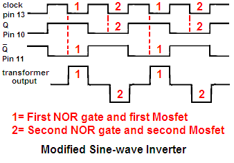 Modified inverter logic.PNG
8.26 KB
Reply author: eng.zahir
Replied on: May 05 2008 01:05:16 AM
Message:
Hi audioguru this is square wave but i need sine wave
Download Attachment: 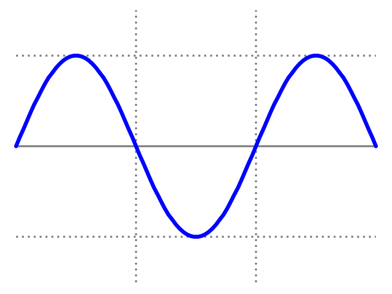 sine_wave.png
19.4 KB
Reply author: akagi
Replied on: May 05 2008 06:08:45 AM
Message:
Hi,
in order to have a sine wave, a low pass filter must be integrated to the circuit so as to remove away the odd harmonics. I would like to know the purpose for the circuit on the top left hand corner, the zener, the cap and the resistor. Can someone assist me?
Reply author: akagi
Replied on: May 05 2008 06:27:48 AM
Message:
another thing is why is there a need for resistors to be present before the gates of the mosfets? is it for reducing the current flowing into the mosfets so as to prevent these power semiconductor switches from drawing high current?
Reply author: audioguru
Replied on: May 05 2008 10:31:33 AM
Message:
A sine-wave has a peak voltage that is 1.414 times the peak voltage of a auare-wave. So a different transformer is used.
A high current filter to convert a 50Hz square-wave to a 50Hz sine-wave will be huge and will have such a high resistance that very low power will be at its output. Most of the power from the inverter will heat the inductor.
A "pure-sine-wave" inverter uses a complicated Pulse-Width-Modulation circuit that operates at a high frequency so its filter parts are small and work properly.
The zener diode and resistor are used to eliminate voltage spikes that will kill the Cmos IC. The capacitor is needed for any electronic circuit.
All Mosfet circuits use a low value resistor in series with each gate close to the Mosfet (some use a ferrite bead) to prevent the Mosfet from oscillating at a VHF or UHF frequency. It will get extremely hot if it oscillates.
A Mosfet does not have input current. A current is needed at its input to quickly charge and discharge its high input capacitance.
Reply author: eng.zahir
Replied on: May 07 2008 08:14:21 AM
Message:
pls any one give me a pure sine wave (50Hz) inverter circuit diagram. PLSSSSSSSSSSSSSSSSSSSSSSSSSSSSSSSSSSSSSS
Reply author: eng.zahir
Replied on: May 09 2008 02:01:37 AM
Message:
pls give me any one 50Hz pure sine wave inverter or Oscillator circuit diagram. plsssssssssssssssssssssssssss
Reply author: audioguru
Replied on: May 09 2008 10:32:38 AM
Message:
A pure sine wave inverter has a very complicated circuit.
Reply author: eng.zahir
Replied on: May 11 2008 11:49:57 PM
Message:
I need a sinve wave oscillator or square to sine wave converter circuit diagra. any one give me plsssssssssssssss
Reply author: audioguru
Replied on: May 12 2008 12:05:14 PM
Message:
It is easy to make a sine-wave oscillator that has low output power. If you feed it to a power amplifier then the amplifier will make a lot of heat and most of the battery power will be wasted.
It is easy to convert a square-wave to a sine-wave at low power.
A sine-wave inverter uses a high frequency oscillator, a small high frequency transformer and Mosfets to make a suitable high voltage then rectifies and filters it. Then it uses a microcontroller to make pulse-width-modulation at 50Hz or 60Hz and feeds an H-bridge with high voltage switching Mosfets that produce the sine-wave with many steps in it, then two small high frequency filters. Negative feedback is used to regulate the output voltage. A shutdown circuit works during over-current, over-temperature and low battery voltage.
Reply author: eng.zahir
Replied on: May 13 2008 02:25:50 AM
Message:
everythings is ok but i need a circuit. pls give me a circuit. plssssssssssss
Reply author: audioguru
Replied on: May 13 2008 10:08:50 AM
Message:
Ask your teacher to give you a circuit of a sine-wave oscillator or pure sine-wave inverter.
Look in Google. There are links to hundreds of sine-wave oscillator circuits. You might even find the very complicated circuit for a pure sine-wave inverter.
Reply author: kivdenn
Replied on: May 14 2008 04:06:46 AM
Message:
quote:
Originally posted by ruaconbeouquote:
Originally posted by liang2408
Hi audioguru,
I have decided to build the circuit with CD4047 together with CD4001 and IRFZ44. Hopefully, it i will be able to get the voltage and waveform that was required.
Just to clarify something, the resistor value that was input to CD4047, can i use a potentiometer instead of fixed value so as i can adjust the frequency accordingly? Furthermore, can i used a 9-0-9/230 with a rated of 36VA instead of 10-0-10/230 transformer. What will be the difference and if not, can i use a 12-0-12/230 transformer? Lastly, there is a capacitor that is connected in series to a resistor of 100/5W. What is the value of the capacitor, is it 220uF and also is it a AC or DC capacitor?
Anyway, thanks for your kindly response.
Download Attachment:
109.42┬ĀKB
Hullo Audioguru, I have built that circuit but the output at pin 10 and pin 11 of the cd4001 is only 6V and you said mosfets turn on when there gate to source voltage is 10V how come these turn on at 6V could it be the reason why its output is low? I also used a 9V-0V-9V/ 230V transformer its no load current draw from the battery is 1ampere why is this? Thanks
Reply author: audioguru
Replied on: May 14 2008 1:15:39 PM
Message:
Pin 10, 11 and 13 of the CD4047 and the outputs of the Cmos gates are a square-wave with a peak voltage of at least 12V and turn on the Mosfets perfectly. The average of 6V might show on a DC voltmeter. An ordinary AC voltmeter will not measure the peak voltage of a square-wave since they are made to measure a sine-wave which is very different.
The no load draw from the battery is only 12W which is low. The quality of the transformer affects how much is the battery current without a load.
Now you say the output is low. Was the voltage at the output low? What was the load? Did you measure the voltage with a True-RMS voltmeter because an ordinary voltmeter cannot measure these digital signals. accurately.
Reply author: goodman
Replied on: Jun 09 2008 12:53:49 PM
Message:
quote:
Originally posted by liang2408
Hi audioguru,
I have decided to build the circuit with CD4047 together with CD4001 and IRFZ44. Hopefully, it i will be able to get the voltage and waveform that was required.
Just to clarify something, the resistor value that was input to CD4047, can i use a potentiometer instead of fixed value so as i can adjust the frequency accordingly? Furthermore, can i used a 9-0-9/230 with a rated of 36VA instead of 10-0-10/230 transformer. What will be the difference and if not, can i use a 12-0-12/230 transformer? Lastly, there is a capacitor that is connected in series to a resistor of 100/5W. What is the value of the capacitor, is it 220uF and also is it a AC or DC capacitor?
Anyway, thanks for your kindly response.
Download Attachment:
109.42ĀKB
Reply author: audioguru
Replied on: Jun 09 2008 3:55:34 PM
Message:
Hi Goodman,
R1 can be a 100k potrentiometer in series with 22k. C1 should be a metalized poly film type.
A 36VA transformer is too small for a power inverter. In this 500W circuit the transformer should be 800VA.
there should be a 100 ohm resistor in series with the positive supply to the ICs and a 15V zener diode and 0.1uf capaciroe to ground. change the 1k resistors to 100 ohms.
A 9V-0-9V 1000VA transformer will be fine.
Use only two Mosfets for a 250W inverter that uses a 400VA transformer.
Reply author: roderman
Replied on: Jul 06 2008 10:23:00 AM
Message:
Would this circuit:
200824215918_20081910308_Modified sine-wave inverter schematic.png
work for a small AC motor (4watts)? Am looking for an inverter
circuit for 115vac/5VA that is kind to motors. Square wave
inverters eat them for breakfast. Any suggestions?
The input is 60Hz/12vdc - so don't need the input circuit.
Thanks for any help/suggestions!
George
Reply author: audioguru
Replied on: Jul 06 2008 10:51:07 AM
Message:
The modified sine-wave is really a modified square-wave. It might also eat your tiny motor.
Make a 5W power amplifier with a stepup transformer and feed it a sine-wave. There are hundreds of car radio amplifier ICs available. If you use a bridged amp then use a 6VAC transformer.
Reply author: kiran.yendlury
Replied on: Jan 20 2009 06:35:20 AM
Message:
hi sir i need a cicuit for 12v/230v 50hz,500w inverter
Reply author: audioguru
Replied on: Jan 20 2009 09:36:06 AM
Message:
There are many simple inverter circuits on the internet. Some work and some don't.
Design the circuit yourself.
Reply author: tech-rachit
Replied on: Apr 26 2009 12:39:29 PM
Message:
plz can u people tell me how to build a sinewave inverter using a 6 v batt. 4.5 Ah
Reply author: tech-rachit
Replied on: Apr 26 2009 12:50:04 PM
Message:
see liang2408
the output at CD4047 will be dc and ac too
the real job is done bt the mosfet
it actually converts 2/4 dc voltage to ac
so i think ur project will be successful
best of luck
Reply author: sympsyd
Replied on: May 01 2009 8:59:18 PM
Message:
quote:
Originally posted by audioguru
Pin 13 of a CD4047 is explained in its datasheet.
It is its 100Hz oscillator output in the inverter which is an output in the IC before the digital frequency divider in it provides the 50Hz outputs at pin 10 and 50Hz inverted output at pin 11.
Look at my sketch to see how the logic makes the signals for the Mosfets:
Download Attachment:
8.26ĀKB
i'm bit confused with this waveforms, can u please epxlain? thank you
Reply author: audioguru
Replied on: May 05 2009 10:29:56 AM
Message:
quote:
Originally posted by sympsyd
i'm bit confused with this waveforms, can u please epxlain? thank you
1) The top trace is the pin13 clock output of the CD4047.
2) The second trace is the Q pin10 output of the CD4047.
3) The third trace is the Q-not pin11 output of the CD4047.
4) The fourth trace is the transformer output because each Mosfet was driven from the outputs of two NOR gates #1 and #2.
A NOR gate has a high output when both inputs are low. The high output turns on the associated Mosfet.
Reply author: tabish abbas
Replied on: Jun 30 2009 01:59:19 AM
Message:
salam i have made this circuit but the problem is same i got 106volts ac wheni apply 15 volts dc but i am using 2700u capacitor b4 inductor. what shall i do 4 increase the ac voltage thanks
Reply author: audioguru
Replied on: Jun 30 2009 08:36:59 AM
Message:
Why this circuit does not work has been explained. It has too many voltage losses.
Reply author: tabish abbas
Replied on: Jun 30 2009 1:48:01 PM
Message:
i am talking about 555 timer circuit it is working but it should give 120 volts ac when provides 5 volts dc .but i give it 5 volts dc it gives 46 volts ac .what shall i do to increase the ac voltsage at output.pleae reply me thanks in advance make sure that i am talking about 555 timer circuit which is at first page first question.
Reply author: audioguru
Replied on: Jun 30 2009 3:33:16 PM
Message:
quote:
Originally posted by tabish abbas
i am talking about 555 timer circuit it is working but it should give 120 volts ac when provides 5 volts dc .but i give it 5 volts dc it gives 46 volts ac .what shall i do to increase the ac voltsage at output.pleae reply me thanks in advance make sure that i am talking about 555 timer circuit which is at first page first question.
The circuit on the first page of this thread uses a high current 12V supply, not 5V.
It uses a very weak Cmos ICM7555 timer, not a more powerful bipolar 555 timer.
It has many voltage losses so its output voltage is too low.
I explained all the voltage losses.
Reply author: tabish abbas
Replied on: Jul 01 2009 04:27:50 AM
Message:
but i am using ne555 should i change 555?which 555 should i use ? to increase ac voltage and there was given that 5 to 15 dc voltage it will provide 120 to 220 ac voltage thats why i wrote 5 volts dc.
Reply author: audioguru
Replied on: Jul 01 2009 11:28:35 AM
Message:
The circuit has too many voltage losses to be an inverter. The output voltage changes with the amount of load current. I think its output waveform is a square-wave because the inductor is much too small.
With a 12V supply the output voltage from an NE555 driving 200mA into the bases of the output transistors is only 7V p-p and the output from the transistors is only 5V p-p. If the capacitor and inductor do not have any internal resistance then a 5V mains transformer will produce a square-wave output that increases when the load current decreases. The max output power is only 7.5W.
Reply author: tabish abbas
Replied on: Jul 02 2009 03:44:11 AM
Message:
sorry for distrub you again but i am confused.what should i do to increase the voltage and power i need 25watt?sorry again but thank you. you are very good and you are giving answer of my question.
Reply author: audioguru
Replied on: Jul 02 2009 08:52:19 AM
Message:
quote:
Originally posted by tabish abbas
what should i do to increase the voltage and power i need 25watt?
The entire circuit and its parts selection needs to be completely re-designed to work properly.
Reply author: tabish abbas
Replied on: Jul 02 2009 2:41:55 PM
Message:
can u re designed for me if you dont mind?please
Reply author: tabish abbas
Replied on: Jul 02 2009 2:46:25 PM
Message:
specially with 555 i needed?
Reply author: audioguru
Replied on: Jul 02 2009 5:58:16 PM
Message:
My electricity is reliable and I don't go "camping" so i don't use and don't need an inverter.
Inverters are cheap to buy now and they are excellent. So why design and make one?
Reply author: tabish abbas
Replied on: Jul 03 2009 11:02:02 AM
Message:
brother i live in pakistan.the big problem over here is load shedding of electricity so thats why i am tring to make my own inverter for 1 fan.
Reply author: audioguru
Replied on: Jul 03 2009 7:06:02 PM
Message:
I am sorry that you live in a weird country.
Here everything works because they were planned properly in advance.
Reply author: tabish abbas
Replied on: Jul 11 2009 03:31:50 AM
Message:
http://www.circuitstoday.com/100-watt-inverter-circuit
can i use 12 volts simple battery not car battery.in the above link circuit please answer me ?
Reply author: audioguru
Replied on: Jul 11 2009 10:58:00 AM
Message:
The 100W inverter has a square-wave output that does not have voltage regulation.
Will your load work from a square-wave?
Will your load care if the voltage is too high when the battery is charged then the voltage is too low when the battery is discharged?
Will your battery be able to supply 10A?
Reply author: jeffreywong
Replied on: Jan 13 2010 10:14:28 AM
Message:
quote:
Originally posted by audioguru
It is easy to make a sine-wave oscillator that has low output power. If you feed it to a power amplifier then the amplifier will make a lot of heat and most of the battery power will be wasted.
It is easy to convert a square-wave to a sine-wave at low power.
A sine-wave inverter uses a high frequency oscillator, a small high frequency transformer and Mosfets to make a suitable high voltage then rectifies and filters it. Then it uses a microcontroller to make pulse-width-modulation at 50Hz or 60Hz and feeds an H-bridge with high voltage switching Mosfets that produce the sine-wave with many steps in it, then two small high frequency filters. Negative feedback is used to regulate the output voltage. A shutdown circuit works during over-current, over-temperature and low battery voltage.
Hi, audioguru, Im doing a pure sine wave inverter, im facing many proble during working on it, i need u assist on it.
1. Can I using SG3526 to generate a PWM instead of microcontroller?
2. If so, If I generate high frequency PWM to switch, how can I use a lowpass filter to change back to 50HZ output? I have try to change it back to 50HZ, but fail to do it, can u teach me?
3. High frequency transformer is very difficult to find, can rewind it by myself by using toroidal core?
4. If i rewind by myself, I fail to search the spec. of the 12V to 240V , 25A tranformer. Do u have anyidea?
Thanks...
Reply author: audioguru
Replied on: Jan 13 2010 11:30:36 AM
Message:
quote:
Originally posted by jeffreywong
Im doing a pure sine wave inverter, im facing many problems during working on it, i need u assist on it.
1. Can I using SG3526 to generate a PWM instead of microcontroller?
I have never seen an inverter because my electricity is reliable. I have also never seen an SG3526 IC. I can buy a cheap Chinese sine-wave inverter that uses two TL494 PWM ICs.
quote:
2. If so, If I generate high frequency PWM to switch, how can I use a lowpass filter to change back to 50HZ output? I have try to change it back to 50HZ, but fail to do it, can u teach me?
You must modulate the PWM with a 50Hz sine-wave.
The lowpass filter is an inductor in series and a capacitor to ground. Simple.
quote:
3. High frequency transformer is very difficult to find, can rewind it by myself by using toroidal core?
I don't know where you will find a ferrite core that does not saturate with the high current in its coil.
quote:
4. If i rewind by myself, I fail to search the spec. of the 12V to 240V , 25A tranformer. Do u have anyidea?
I don't know the spec's of a high frequency power transformer.
Reply author: jeffreywong
Replied on: Jan 14 2010 04:10:48 AM
Message:
quote:
Originally posted by audioguru
It is easy to make a sine-wave oscillator that has low output power. If you feed it to a power amplifier then the amplifier will make a lot of heat and most of the battery power will be wasted.
It is easy to convert a square-wave to a sine-wave at low power.
A sine-wave inverter uses a high frequency oscillator, a small high frequency transformer and Mosfets to make a suitable high voltage then rectifies and filters it. Then it uses a microcontroller to make pulse-width-modulation at 50Hz or 60Hz and feeds an H-bridge with high voltage switching Mosfets that produce the sine-wave with many steps in it, then two small high frequency filters. Negative feedback is used to regulate the output voltage. A shutdown circuit works during over-current, over-temperature and low battery voltage.
I have some confusing about it.
What u mean is that a pure sine wave inverter have to transform a 12VDC to 240VDC then use mosfet switches to invert 240VDC to 240VAC.
My question is how can the DC power can run in transformer?
thanks...
Reply author: wasssup1990
Replied on: Jan 14 2010 07:02:47 AM
Message:
I think you mean 340VDC to 240AC RMS.
A change in voltage on the primary will cause all secondary coils to produce a derivative voltage. If you single out a 10% PWM duty cycle you will see that for 10% of a PWM cycle the primary coil is being energized - current is increasing in the primary so voltage is being induced in all secondaries. If you put a near 100% duty cycle on the primary, each cycle should only just reach the saturation point of the core material used in the transformer - for maximum efficiency.
In case you didn't understand what I just said in the middle of my last paragraph. The DC part can be confusing to Noobs because it isn't a constant DC. The current on the primary goes from 0 Amps up to V/R where R is the resistance of the coil. So even though you have pulsed a constant voltage across the primary, the primary DC is increasing from 0 Amps over time which in so doing induces a voltage in all secondary coils. I suggest you go and open an electronics book. You'll learn a lot more and a lot quicker than any of us can teach you. Just like everything in the universe, a change of some sort is needed to do any kind of action. The same with transformers - a stepped constant voltage causes a change in current in any kind of medium which conducts electricity until it reaches a maxima of V/R. I could go on and on...
Happy thinking ![]()
Reply author: jeffreywong
Replied on: Jan 14 2010 9:04:24 PM
Message:
quote:
Originally posted by audioguru
It is easy to make a sine-wave oscillator that has low output power. If you feed it to a power amplifier then the amplifier will make a lot of heat and most of the battery power will be wasted.
It is easy to convert a square-wave to a sine-wave at low power.
A sine-wave inverter uses a high frequency oscillator, a small high frequency transformer and Mosfets to make a suitable high voltage then rectifies and filters it. Then it uses a microcontroller to make pulse-width-modulation at 50Hz or 60Hz and feeds an H-bridge with high voltage switching Mosfets that produce the sine-wave with many steps in it, then two small high frequency filters. Negative feedback is used to regulate the output voltage. A shutdown circuit works during over-current, over-temperature and low battery voltage.
I have some confuse.
In the last part, you said that it use a microcontroller to generate a 50HZ PWM to drive the switches, so why it still need a high frequency filter to filter it since the PWM generate is only 50HZ?
thanks...
Reply author: wasssup1990
Replied on: Jan 15 2010 12:53:28 AM
Message:
OMG Jeffrey go and read some electronics books. Do you not understand how PWM works? You're modulating the width of a pulse with a sine 50Hz. The cycle length of a single PWM cycle should be several times smaller in order to reproduce the modulating wave form in PWM. The filter is designed to oscilate at 50Hz and will not pass the PWM frequency of which should be several times higher than the 50Hz modulating signal.
Is it a language barrier for you? I don't know.
Reply author: audioguru
Replied on: Jan 15 2010 6:20:34 PM
Message:
We speak English here. I don't know why people from the other side of the world come here when they "no speeky zee engrish".
The power oscillator that steps up the 12V to 340V is at a high frequency so so a small ferrite high frequency transformer is used.
The high frequency is modulated by a 50Hz sine-wave. The modulated high frequency drives the Mosfet H-bridge and an LC filters out the high frequency switching carrier frequency.
Reply author: wasssup1990
Replied on: Jan 15 2010 8:08:13 PM
Message:
We're just walking in circles now.
Reply author: abdulgtm
Replied on: Jan 17 2010 02:14:33 AM
Message:
Dear <
Still have u completed ur project or pending , let me know may I becmae help u in this regard
Abdul
Reply author: sb5_csn
Replied on: Jan 01 2016 10:37:24 PM
Message:
sir, due to connecting"CD4001 ic" over heating in ic is occured. please, give a solution in this page.
Reply author: audioguru
Replied on: Jan 02 2016 09:23:08 AM
Message:
quote:
Originally posted by sb5_csn
sir, due to connecting"CD4001 ic" over heating in ic is occured. please, give a solution in this page.
I do not know the circuit you have that uses a CD4001 IC. Please post the schematic.
The datasheet from Texas Instruments shows the typical output current.
When the IC uses a 5V supply its maximum output current is only a few mA, maybe 5mA per output when shorted. Then the IC heats with 5mA x 4 x 5V= 0.1W and it will be warm. ARE YOU SHORTING ALL 4 OUTPUTS?
When the IC uses a 10V supply its maximum output current is about 22mA per output when shorted. Then the IC heats with 22mA x 4 x 10V= 0.88W which will burn it.
When it has a high impedance load (another CMOS input) then it does not heat up. What is it driving?
Reply author: audioguru
Replied on: Jan 02 2016 09:50:10 AM
Message:
The circuit that was posted in this thread 8 years ago uses a CD4001 Cmos logic IC powered from a 12V battery and it drives Mosfets that have no input current. The frequency is low and the current is extremely low so the CD4001 IC does not get warm.
Maybe the circuit is missing the resistor feeding a zener diode and capacitor as shown here and voltage spikes have destroyed the IC?
Download Attachment: 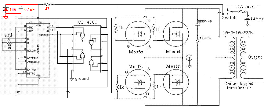 modified sinewave inverter.png
118.96ĀKB
Reply author: sb5_csn
Replied on: Jan 03 2016 07:52:06 AM
Message:
sir, i used lm7812 voltage regulator without using 47 ohm resistor,0.1 uf capacitor and 16volt zenar diode.so,is this condition responsible for over heating of ic cd4001.
Reply author: audioguru
Replied on: Jan 03 2016 1:29:02 PM
Message:
Measure the output voltage of the 12V regulator. If it is higher than 15V then it and the CD4001 are destroyed. The resistor, zener diode and capacitor prevent their destruction and should always be used in that circuit.
The CD4001 is feeding the gates of Mosfets that use no current so the CD4001 should be cold and not be hot. Maybe the voltage regulator, cD4001 and also the Mosfets are destroyed because you did not use the resistor, zener diode and capacitor. Maybe the CD4001 is destroyed because it had its 12V connected backwards.
Reply author: sb5_csn
Replied on: Jan 03 2016 11:16:07 PM
Message:
sir,can i use lm7805 without using 470 ohm resistor
Reply author: sb5_csn
Replied on: Jan 03 2016 11:18:47 PM
Message:
sorry,it was 47 ohm resistor
Reply author: audioguru
Replied on: Jan 04 2016 8:16:44 PM
Message:
Why use a 7805? Its output voltage is only 5V so the output transistors or Mosfets barely turn on and the output power from the inverter will be very low. The CD4001 needs to be powered from 12V but a 7812 12V regulator needs an input of at least 14.5V to work properly.
Aaron's Homepage Forum : http://www.aaroncake.net/forum/
© 1995-2020 AARONCAKE.NET