| T O P I C R E V I E W |
| kivdenn |
Posted - Dec 08 2009 : 03:25:58 AM
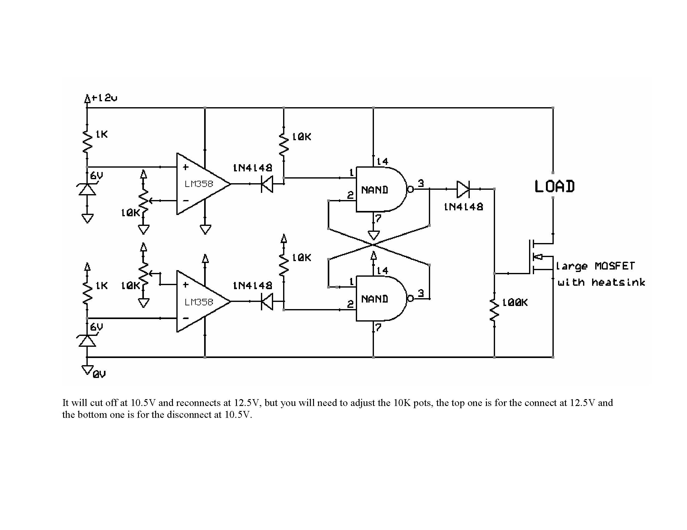
Hi all I have got this LVD circuit and built it, it works just the way the designer intended it to but the problem is that he made the reconnection limit to be at 12.5V which is too high. I would like to reduce the reconect voltage to 11.5V so that it shuts down at 10.5V and reconnects at 11.5V but Iam not sure on what parts to change though my intution tells me it must be one of the 10k variable resistors. I failed to get the contact of the original designer thats why I have am using this site for views and opinions. Thanks
Dennis
Download Attachment:  LVD.jpg LVD.jpg
151.01 KB
 |
| 7 L A T E S T R E P L I E S (Newest First) |
| ron roberts |
Posted - Jan 03 2010 : 1:34:48 PM
Hi kivdenn I�m new to this forum and I was looking for a diagram like the one you have posted above but then came across this one that may be of some interest to you.
I have used this one, it�s from a different forum but it as a good schematic and it works as you describe.
This is a link to the pic of the diagram

There�s all so a video of it working on YouTube
Again this is the link to that video.
http://www.youtube.com/watch?v=BbQQYEsxDpg
and that�s not all he as a downloadable to scale diagram.
This link will take you to the place where you can download it just look for
Diagram for the Auto battery swapper.
At this link.
http://teep.forumco.com/topic~TOPIC_ID~87.asp |
| audioguru |
Posted - Dec 12 2009 : 09:55:02 AM
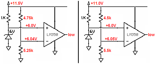
I made part of your schematic small enough so that it is not as big as my city.
I turned up the "re-connect" pot a little above half-way and show that the circuit works with a battery of 11.5V and also turned up a little more the circuit will also work with a battery of 11.0V.
Download Attachment: battery re-connect circuit.PNG
21.84 KB
 |
| kivdenn |
Posted - Dec 12 2009 : 04:02:02 AM
Correction: When in adjust the top reconnect pot to its minimum the reconnect voltage is 12.5V. I want it to reconnect at 11.5V such that the circuit disconects at 10.5V abnd reconnects at 11.5V. Thanks |
| audioguru |
Posted - Dec 11 2009 : 09:50:52 AM
Then your zener diodes are not 6.0V or your opamps are not an LM358. You should be able to adjust the minimum to almost 7V and the maximum to almost 18V.
The input current of the opamps is so low that almost any value of pot will work the same.
Maybe you used opamps with different part numbers? |
| kivdenn |
Posted - Dec 11 2009 : 07:03:45 AM
When i adjust to the minumum it cuts off at 12.5V and the maximum is above 14V. I think the value of one of the variable resistor has to be changed, bit I cant tell which and what value, please help me with that. Thanks |
| audioguru |
Posted - Dec 10 2009 : 11:36:41 AM
The text on the bottom of the huge schematic tells you to adjust the pots. So why don't you adjust the pots? |
| kivdenn |
Posted - Dec 10 2009 : 02:45:20 AM
Some body please help me with this. Thanks |