Aaron's Homepage Forum
Home | Profile | Register | Active Topics | Members | Search | FAQ
 All Forums
 Electronics
 Other Circuits
 Calculating frequencies for Spectrum Analyzer

Note: You must be registered in order to post a reply.
To register, click here. Registration is FREE!

Screensize:
UserName:
Password:
Format Mode:
Format: BoldItalicizedUnderlineStrikethrough Align LeftCenteredAlign Right Horizontal Rule Insert HyperlinkInsert EmailInsert Image Insert CodeInsert QuoteInsert List
   
Message:

* HTML is OFF
* Forum Code is ON
Smilies
Smile [:)] Big Smile [:D] Cool [8D] Blush [:I]
Tongue [:P] Evil [):] Wink [;)] Clown [:o)]
Black Eye [B)] Eight Ball [8] Frown [:(] Shy [8)]
Shocked [:0] Angry [:(!] Dead [xx(] Sleepy [|)]
Kisses [:X] Approve [^] Disapprove [V] Question [?]

   Insert an Image File (GIF, JPG, JPEG, BMP, ZIP, PNG)


T O P I C    R E V I E W
jmc2385 Posted - May 09 2014 : 09:14:16 AM
Hey Aaron,

I came across your spectrum analyzer (http://www.aaroncake.net/circuits/3chspec.asp) via this site (http://makezine.com/2010/10/18/circuit-skills-led-color-organ-spon/), and I'm currently working on making my own version of it.

Could I ask you if you have a formula for calculating the frequency and bandwidth of each of the bandpass filters you made? I wanted to add more bands and adjust the frequencies and bandwidth of each band, but I need a way to determine which parts I should use to get the results I want.

I found a calculator here http://www.muzique.com/lab/gyrator.htm , but it is a different circuit design so I can't use it to calculate the frequency or bandwidth (Q) with your circuit.

Any help is much appreciated.

Thanks!

- Joe
1   L A T E S T    R E P L I E S    (Newest First)
audioguru Posted - May 12 2014 : 11:05:56 AM
The project uses an odd LM3900 quad amplifier IC and a Japanese LED driver that is obsolete.

The filters are not gyrator but are called Multiple Feedback Bandpass Filter and the calculation of parts and frequency are shown in Google.

The bandpass is wrong for a spectrum analyser since the peak is narrow-band and the simple skirts are gradual and wide-band.
A spectrum analyser needs filters with a response that has a flat amplitude for its bandpass then sharp skirts.

Here is a simulation of the response of a Multiple Feedback Bandpass Filter:

Download Attachment: 
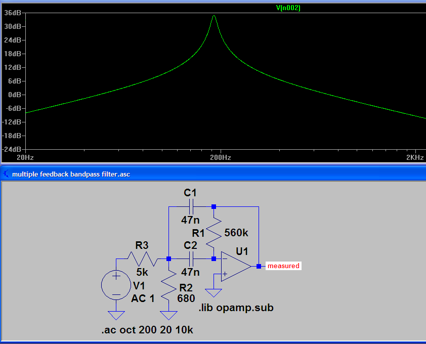
multiple feedback bandpass filter response.PNG
26.44 KB


Aaron's Homepage Forum © 1995-2020 AARONCAKE.NET Go To Top Of Page
This page was generated in 0.05 seconds. Snitz Forums 2000