| Author |
 Topic Topic  |
|
eng.zahir
Apprentece

Bangladesh
7 Posts |
 Posted - May 09 2008 : 02:01:37 AM Posted - May 09 2008 : 02:01:37 AM


|
| pls give me any one 50Hz pure sine wave inverter or Oscillator circuit diagram. plsssssssssssssssssssssssssss |
 |
|
|
audioguru
Nobel Prize Winner

Canada
4218 Posts |
Posted - May 09 2008 : 10:32:38 AM
|
| A pure sine wave inverter has a very complicated circuit. |
|
|
|
eng.zahir
Apprentece
Bangladesh
7 Posts |
Posted - May 11 2008 : 11:49:57 PM
|
| I need a sinve wave oscillator or square to sine wave converter circuit diagra. any one give me plsssssssssssssss |
|
|
|
audioguru
Nobel Prize Winner
Canada
4218 Posts |
Posted - May 12 2008 : 12:05:14 PM
|
It is easy to make a sine-wave oscillator that has low output power. If you feed it to a power amplifier then the amplifier will make a lot of heat and most of the battery power will be wasted.
It is easy to convert a square-wave to a sine-wave at low power.
A sine-wave inverter uses a high frequency oscillator, a small high frequency transformer and Mosfets to make a suitable high voltage then rectifies and filters it. Then it uses a microcontroller to make pulse-width-modulation at 50Hz or 60Hz and feeds an H-bridge with high voltage switching Mosfets that produce the sine-wave with many steps in it, then two small high frequency filters. Negative feedback is used to regulate the output voltage. A shutdown circuit works during over-current, over-temperature and low battery voltage. |
|
|
|
eng.zahir
Apprentece
Bangladesh
7 Posts |
Posted - May 13 2008 : 02:25:50 AM
|
| everythings is ok but i need a circuit. pls give me a circuit. plssssssssssss |
|
|
|
audioguru
Nobel Prize Winner
Canada
4218 Posts |
Posted - May 13 2008 : 10:08:50 AM
|
Ask your teacher to give you a circuit of a sine-wave oscillator or pure sine-wave inverter.
Look in Google. There are links to hundreds of sine-wave oscillator circuits. You might even find the very complicated circuit for a pure sine-wave inverter. |
|
|
|
kivdenn
Nobel Prize Winner
Uganda
535 Posts |
Posted - May 14 2008 : 04:06:46 AM
|
quote:
Originally posted by ruaconbeou
quote:
Originally posted by liang2408
Hi audioguru,
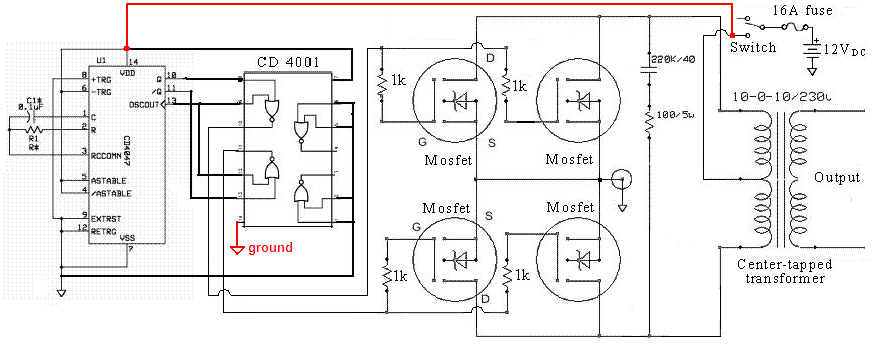
I have decided to build the circuit with CD4047 together with CD4001 and IRFZ44. Hopefully, it i will be able to get the voltage and waveform that was required.
Just to clarify something, the resistor value that was input to CD4047, can i use a potentiometer instead of fixed value so as i can adjust the frequency accordingly? Furthermore, can i used a 9-0-9/230 with a rated of 36VA instead of 10-0-10/230 transformer. What will be the difference and if not, can i use a 12-0-12/230 transformer? Lastly, there is a capacitor that is connected in series to a resistor of 100/5W. What is the value of the capacitor, is it 220uF and also is it a AC or DC capacitor?
Anyway, thanks for your kindly response.
Download Attachment:  20081910308_Modified sine-wave inverter schematic.png 20081910308_Modified sine-wave inverter schematic.png
109.42 KB
Hullo Audioguru, I have built that circuit but the output at pin 10 and pin 11 of the cd4001 is only 6V and you said mosfets turn on when there gate to source voltage is 10V how come these turn on at 6V could it be the reason why its output is low? I also used a 9V-0V-9V/ 230V transformer its no load current draw from the battery is 1ampere why is this? Thanks |
|
|
|
audioguru
Nobel Prize Winner
Canada
4218 Posts |
Posted - May 14 2008 : 1:15:39 PM
|
Pin 10, 11 and 13 of the CD4047 and the outputs of the Cmos gates are a square-wave with a peak voltage of at least 12V and turn on the Mosfets perfectly. The average of 6V might show on a DC voltmeter. An ordinary AC voltmeter will not measure the peak voltage of a square-wave since they are made to measure a sine-wave which is very different.
The no load draw from the battery is only 12W which is low. The quality of the transformer affects how much is the battery current without a load.
Now you say the output is low. Was the voltage at the output low? What was the load? Did you measure the voltage with a True-RMS voltmeter because an ordinary voltmeter cannot measure these digital signals. accurately. |
|
|
|
goodman
New Member
Nigeria
1 Posts |
Posted - Jun 09 2008 : 12:53:49 PM
|
quote:
Originally posted by liang2408
Hi audioguru,
I have decided to build the circuit with CD4047 together with CD4001 and IRFZ44. Hopefully, it i will be able to get the voltage and waveform that was required.
Just to clarify something, the resistor value that was input to CD4047, can i use a potentiometer instead of fixed value so as i can adjust the frequency accordingly? Furthermore, can i used a 9-0-9/230 with a rated of 36VA instead of 10-0-10/230 transformer. What will be the difference and if not, can i use a 12-0-12/230 transformer? Lastly, there is a capacitor that is connected in series to a resistor of 100/5W. What is the value of the capacitor, is it 220uF and also is it a AC or DC capacitor?
Anyway, thanks for your kindly response.
Download Attachment: 20081910308_Modified sine-wave inverter schematic.png
109.42�KB
|
|
|
|
audioguru
Nobel Prize Winner
Canada
4218 Posts |
Posted - Jun 09 2008 : 3:55:34 PM
|
Hi Goodman,
R1 can be a 100k potrentiometer in series with 22k. C1 should be a metalized poly film type.
A 36VA transformer is too small for a power inverter. In this 500W circuit the transformer should be 800VA.
there should be a 100 ohm resistor in series with the positive supply to the ICs and a 15V zener diode and 0.1uf capaciroe to ground. change the 1k resistors to 100 ohms.
A 9V-0-9V 1000VA transformer will be fine.
Use only two Mosfets for a 250W inverter that uses a 400VA transformer. |
|
|
|
roderman
New Member
USA
1 Posts |
Posted - Jul 06 2008 : 10:23:00 AM
|
Would this circuit:
200824215918_20081910308_Modified sine-wave inverter schematic.png
work for a small AC motor (4watts)? Am looking for an inverter
circuit for 115vac/5VA that is kind to motors. Square wave
inverters eat them for breakfast. Any suggestions?
The input is 60Hz/12vdc - so don't need the input circuit.
Thanks for any help/suggestions!
George
|
|
|
|
audioguru
Nobel Prize Winner
Canada
4218 Posts |
Posted - Jul 06 2008 : 10:51:07 AM
|
The modified sine-wave is really a modified square-wave. It might also eat your tiny motor.
Make a 5W power amplifier with a stepup transformer and feed it a sine-wave. There are hundreds of car radio amplifier ICs available. If you use a bridged amp then use a 6VAC transformer. |
|
|
|
kiran.yendlury
New Member
India
1 Posts |
Posted - Jan 20 2009 : 06:35:20 AM


|
| hi sir i need a cicuit for 12v/230v 50hz,500w inverter |
nani |
|
|
|
audioguru
Nobel Prize Winner
Canada
4218 Posts |
Posted - Jan 20 2009 : 09:36:06 AM
|
There are many simple inverter circuits on the internet. Some work and some don't.
Design the circuit yourself. |
|
|
|
tech-rachit
New Member
India
4 Posts |
Posted - Apr 26 2009 : 12:39:29 PM
|
plz can u people tell me how to build a sinewave inverter using a 6 v batt. 4.5 Ah
|
RHP |
|
|
|
Topic |
|