| Author |
 Topic Topic  |
|
|
exilus
New Member
4 Posts |
 Posted - Dec 14 2009 : 01:32:07 AM Posted - Dec 14 2009 : 01:32:07 AM


|
Hi,
I need to build a circuit that cutoff the battery (3,7v lipo) when it goes under 3v so I wont dammage it. I searched for a few hour on the google but can't find anything good.
Can anyone help me ? |
Edited by - exilus on Dec 15 2009 09:14:12 AM |
|
|
audioguru
Nobel Prize Winner

Canada
4218 Posts |
Posted - Dec 14 2009 : 10:31:48 AM
|
Use a comparator or opamp plus a voltage reference.
An LM10 is an opamp plus an adjustable voltage reference that works with a supply as low as 1.1V and is perfect for your application. It would switch off a low voltage Mosfet that applies power to the load. It is in an 8-pins DIP case. |
 |
|
|
exilus
New Member
4 Posts |
Posted - Dec 14 2009 : 2:40:31 PM
|
Thanx for your help,
The datasheet is not giving much detail about that kind of circuit (the LM10).
I understand the basic concept of using the o amp as a comparator but the schemas I found on google were very different to each other and I'm not sure what would be the best one for me. the cut-off circuit is betwen a the battery and a 2,5v Low dropout regulator, may be I could use the 2,5v as the reference (or reduce it with a resistor).
can you give me a few more details ?!
|
Edited by - exilus on Dec 14 2009 5:06:20 PM |
|
|
|
audioguru
Nobel Prize Winner
Canada
4218 Posts |
Posted - Dec 14 2009 : 4:48:55 PM
|
| Use your 2.5V as the reference voltage for one input of a comparator or opamp and use a voltage divider with two resistors to make the other input the same voltage when the battery drops to the voltage you want cutoff at. |
|
|
|
exilus
New Member
4 Posts |
Posted - Dec 14 2009 : 5:32:28 PM
|
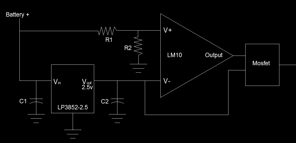
I made a drawing on AutoCAD,
Is it good ?
I copied the schema from de the datasheet for the 2,5v regulator.
I did not calculate the resistors value yet
Download Attachment:  cutoff.JPG cutoff.JPG
44.37 KB
 |
Edited by - exilus on Dec 14 2009 5:57:12 PM |
|
|
|
audioguru
Nobel Prize Winner
Canada
4218 Posts |
Posted - Dec 14 2009 : 7:23:32 PM
|
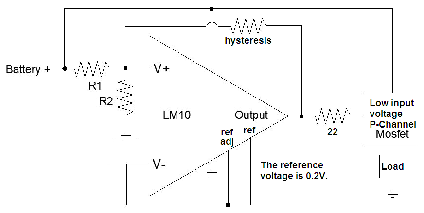
Your schematic was a negative so I inverted it into a positive like most other schematics.
I didn't bother reducing its huge size.
I used the voltage reference inside the LM10 and added hysteresis for a snap action. If the hysteresis is too small then the circuit might oscillate because the battery voltage will rise when the load is disconnected then the circuit will connect the load again.
Adjust the resistors in the voltage divider so that the (+) input is +0.2V when the battery drops to +3.0V.
Download Attachment: low voltage cutoff circuit.PNG
45.48 KB
 |
|
|
|
exilus
New Member
4 Posts |
Posted - Dec 14 2009 : 8:23:16 PM
|
Thanx a lot,
Can you tell me what pin number is "Ref adj" and what might be the value for the hysteresis resistor and the resistor you added between LM10 and Mosfet??
|
|
|
|
audioguru
Nobel Prize Winner
Canada
4218 Posts |
Posted - Dec 14 2009 : 10:50:28 PM
|
quote:
Originally posted by exilus
Can you tell me what pin number is "Ref adj"
Don't you look at datasheets?
The datasheet calls it Reference Feedback.
The datasheet also shows all other pins.
quote:
what might be the value for the hysteresis resistor
It depends on the parallel value of the voltage divider resistors that are calculated using Ohm's Law. The hysteresis resistor will be pretty high, maybe 470k.
quote:
the resistor you added between LM10 and Mosfet??
I show it as 22 ohms. It should be mounted at the Mosfet's gate pin.
[/quote] |
|
|
|
tban07
New Member
4 Posts |
Posted - Sep 23 2013 : 10:41:39 PM
|
Hi, I need some help:
I was recently looking for a circuit to cut-off a battery from a load when the battery voltage reaches a certain threshold. I found the circuit diagrammed (by audioguru) in this thread and thought I'll give it a try.
Setting it up on a breadboard I found that the circuit works but it's logic is opposite to what I need. This circuit connects the battery to the load only when the voltage drops below the threshold I set (when the voltage divider yields less than 0.2V on the +input pin of the LM10)
I am looking to have the battery connected to the load while its voltage is above the threshold and disconnected when the voltage is below the threshold.
Did I not set up the circuit properly or do I need to modify it?
P.S - I cannot use an SPDT relay to reverse the logic because that would defeat the purpose which is to completely isolate the battery from the load so it's not drained to an unsafe level before someone gets to the device.
See circuit diagram attached,
Thanks.
Download Attachment: low voltage cutoff circuit.PNG
45.38 KB |
|
|
|
audioguru
Nobel Prize Winner
Canada
4218 Posts |
Posted - Sep 24 2013 : 11:51:40 AM
|
OOps, with a P-channel Mosfet then the logic is backwards.
I changed the Mosfet to an N-channel type then it does what you want.
Download Attachment: low voltage cutoff circuit2.png
50.57 KB |
|
|
|
tban07
New Member
4 Posts |
Posted - Sep 24 2013 : 11:23:43 PM
|
| Thanks audioguru. I suspected it had to do with the GS voltage on a P-channel mosfet needing to be negative but my understanding of these things is so basic that I did not know where to go with that. And thanks for including a correction to the diagram. |
|
|
|
tban07
New Member
4 Posts |
Posted - Oct 27 2013 : 2:48:27 PM
|
quote:
Originally posted by audioguru
OOps, with a P-channel Mosfet then the logic is backwards.
I changed the Mosfet to an N-channel type then it does what you want.
Download Attachment: low voltage cutoff circuit2.png
50.57�KB
Hi again,
It's been a busy month but I finally got time to put together the corrected circuit with the N-channel Mosfet. Logically, this circuit works as needed but I'm encountering another problem I hope you can shed some light on.
As a reminder, the objective is to disconnect a load from a battery when the battery reaches a certain voltage.
The issue is that the reference (pin#1 on the LM10) does not maintain a steady voltage. At first, I was reading 197mv on it as expected. I then powered the load but the circuit would fail to disconnect it when the voltage of the voltage divider (pin#3) dropped below 197mv. At that point I measured only 45mv on pin#1. This happened with two separate LM10 chips.
Today a new behavior started. I now get 222mv on pin#1 (with 263mv on Pin#3). Then when I power up the load (with a separate switch on the load itself) the voltage at pin#8 rises up to 270mv disconnecting the load within one second. So the circuit is working... but the reference voltage does not stay at 0.2v
I am wondering if I confused the pinouts on the LM10. Here is what I got (corresponding to diagram):
Pin1 - Ref
Pin2 - V-
Pin3 - V+ (voltage divider)
Pin4 - ground (Battery negative)
Pin5 - not in use - should it be?
Pin6 - Output
Pin7 - Battery +
Pin8 - Ref Adj (pins 1,2 and 8 are connected together)
I got:
R1=10K
R2=+-40ohm for roughly 15V (desired cutoff voltage)
Hysteresis=470K
Any idea what would cause this?
Thanks |
|
|
|
audioguru
Nobel Prize Winner
Canada
4218 Posts |
Posted - Oct 27 2013 : 9:23:59 PM
|
R2 should have 200mV across it at cutoff.
For a cutoff voltage of 15V then R1 should have 14.8V across it.
The current in R1 at cutoff is 14.8V/10k= 1.48mA. Then R2 should be 0.2V/1.48mA= 135 ohms, not 40 ohms.
Nearly all electronic circuits oscillate if there is no supply bypass capacitor. Therefore the capacitor is assumed to be there but maybe you do not have one. Connect a 10uf capacitor close to pin 7 and pin 4.
The reference is an accurate voltage source. Its voltage should not change much (maximum 0.2 mV) when the load current changes a few mA (but the load current is very low and does not change in your circuit) and when the supply voltage changes a lot.
|
|
|
|
tban07
New Member
4 Posts |
Posted - Oct 29 2013 : 10:01:42 PM
|
| Thanks AudioGuru. I'll have to keep playing with this circuit when I get the time. I'm not at all sure I set it up right because the reference voltage is changing drastically in response to the load being powered up. This does not seem like a common oscillation. Also, the battery voltage seems stable even when the load powers up. |
|
|
|
NickBell
New Member
USA
1 Posts |
Posted - Mar 19 2014 : 6:30:19 PM
|
I have this circuit and I want to modify it to a voltage cut off of 3.3 volts. Currently it is 4.65v
It's originally designed to work at an input voltage around 7.2.... I'm trying to adapt it to an input of 4.2.
Can you help?
Of course I'm struggling to upload the picture
The two resistors are 750r and 390r
What do I need to change these to |
Edited by - NickBell on Mar 19 2014 6:34:59 PM |
|
|
| |
Topic |
|
 low voltage cutoff circuit.PNG
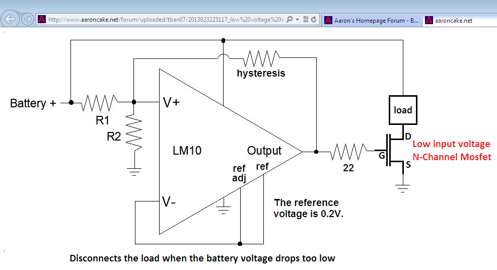 low voltage cutoff circuit2.png