| Home > My Projects > Campbell Hausfeld Air Compressor Upgrade: Oil-less 5CFM To Twin Cylinder 14 CFM |
| Home > My Projects > Campbell Hausfeld Air Compressor Upgrade: Oil-less 5CFM To Twin Cylinder 14 CFM |
Date Of Project: April 2011
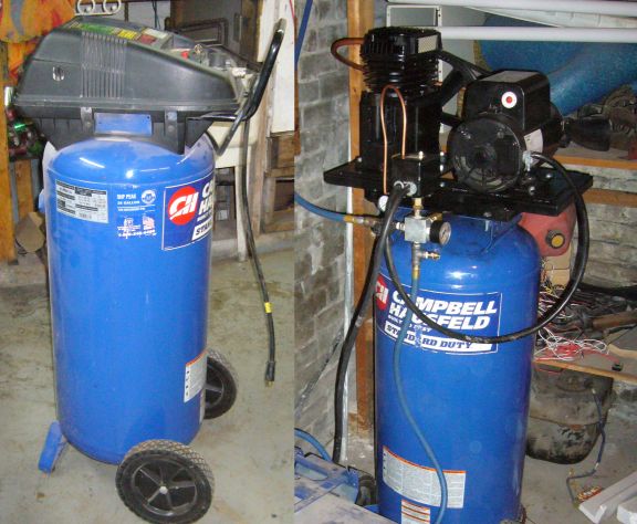
The Campbell Hausfeld WL660301AJ single cylinder oil-less compressor is a great air compressor for home use, it was just not enough compressor for my shop. It was out of its element being connected to an air system and being asked to run air hungry tools like a sand blaster, air sanders, HVLP spray guns, and the like. The little oil-less 5 CFM (and that 5 CFM rating is only at 90 PSI) pump was working constantly to literally the point of failure. It didn't take long to burn out the first "5 HP" motor. Then later on as I was overhauling the pump to replace a broken piston ring, I knew it was time to upgrade.
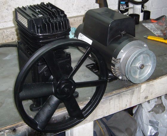
I kept my eye out for a good deal on a slightly used industrial compressor or a sale on a large consumer compressor but most available were either too small, or way too large. It was at that time that several favorable coincidences occurred. The first was that a long time customer blew the pump on their 5HP 18 CFM, 80 gallon compressor. While they wanted the tank to extend the capacity of their new compressor, I was free to take the (almost new) 5 HP 240V motor. For the second, I was at the local Princess Auto store picking some stuff up and ran across a 2 cylinder 14 CFM compressor pump priced at $99 on clearance, marked down from $259.99.
The 3rd, and far more tragic, was that the very next weekend, a faulty block heater on a service truck caused that customer's office to be burned to the ground. Luckily no one was injured but the building and almost everything in it was a total loss. While I was digging through the rubble looking for hard drives to recover, I was told that I could take whatever I wanted off of the compressor (which had survived in the concrete utility room). I was thus able to obtain a suitably rated pressure switch as well as a check valve and various fittings.
I now had all the components needed to construct a new pump and motor assembly to replace the existing underpowered mechanicals of the Campbell Hausfeld compressor.
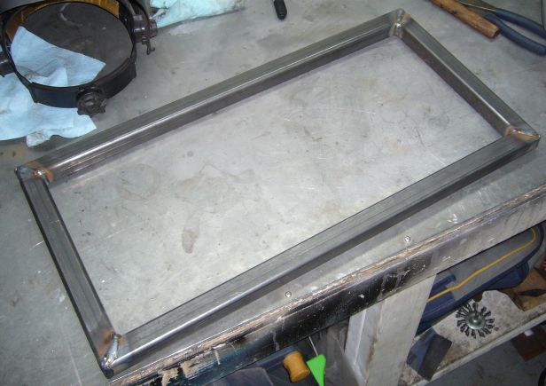
Of course there was no room on the top of the Campbell Hausfeld tank for the much larger pump and motor so the first step in the upgrade was to construct a frame to mount it all on. I started by cutting some 1/8" wall 1" square steel tubing to lengths of 22" and 11". The size was chosen by laying out the motor and pump on the bench, figuring room for fittings and belts, and then adding some padding to each side. I cut the corners to nice 45 degree mitres for a strong joint.
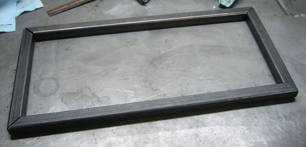
Each side of the frame was held in a 90 degree welding vice and then MIG welded on three sides. Note that the edges were beveled heavily with a grinder to not only ensure good weld penetration but to also minimize the grinding necessary after welding.
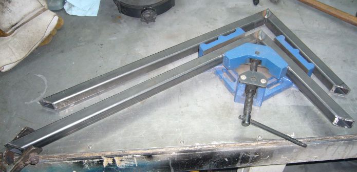
The frame was allowed to totally cool in the vice to help keep things aligned, then each "L" shaped side was positioned to form the rectangle and heavily tacked in place. Square was checked by measuring corner to corner and then the frame was fully welded. Welding up square frames really is an art form and keeping them dimensionally accurate depends heavily on knowing how and where to weld to work with the way metal wants to warp and not against it.
Next up were the mounting plates for the motor and pump. As luck would have it, the local metal shop had two plates of 1/4" steel already cut to perfect dimensions for the frame. These plates measure 9" by 10" and sit quite well on top of the frame, providing a large welding edge. Even better, because all this steel was made up of off cuts from larger jobs, I was able to buy it all by weight for a fraction of retail price. I think I may have all of $15 into the steel needed to make this project. Cutting 1/4" plate not high on my list of ways to spend time so it was nice to have it all sized and ready to go.
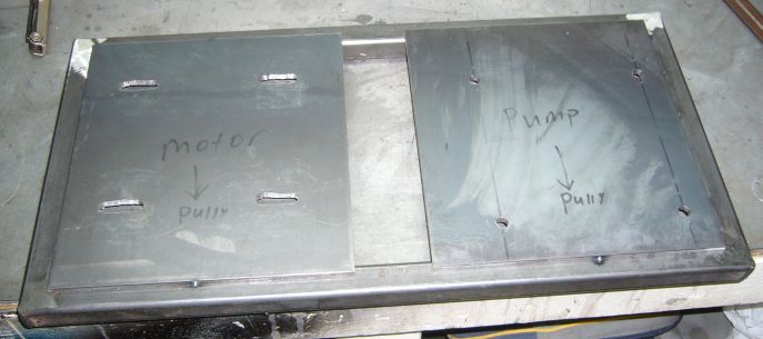
I tacked the plates in place on the frame after grinding down the top and bottom corner welds. Then, the pump and motor were mocked into place and the mounting holes for each were marked to the plates. A ruler was used to keep the motor and pump pulleys aligned. Since the motor needs to be able to move back and forth to adjust belt tension, slots were created by drilling a hole at each end and then cutting out the middle with a jig saw. The motor itself also has roughly 1" slots on its mounting base so there is quite a bit of forward and back movement available. Additionally, the pump holes are drilled a little large to allow the pump a little movement for final belt alignment.
After verifying the fit of the motor and pump, the plates were burned into place. The little 90A Lincoln Electric MIG had it's work cut out for it, dealing with all this thick metal. I'd say that the strength of the welds are acceptable for the purposes of this project. Looking back, I should have run thicker wire, or flux core, or used the TIG.
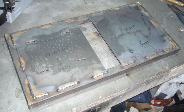
Note that the plates were welded below as well as on top.
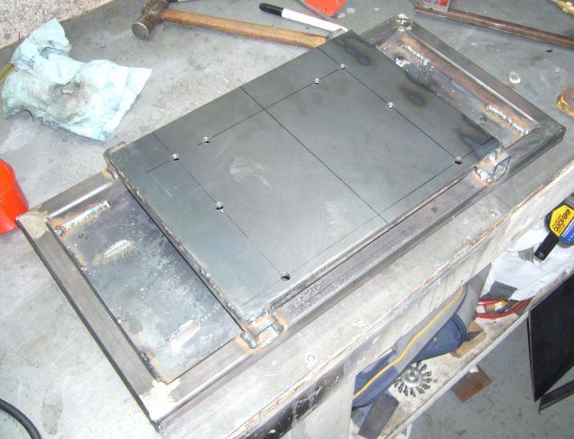
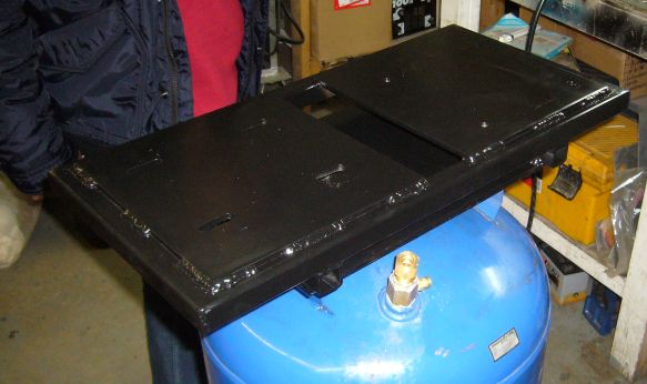
One of the goals of this project was to make the pump upgrade a direct bolt on to the C & H tank, requiring no modifications beyond drilling some mounting holes. It's flat out unsafe to weld anything to a compressor tank and who knows, in the future, I might want to return the compressor to stock and sell it (if I come across a tank upgrade, for example). To accomplish this I took some measurements from the stock tank mounting plate and then drilled another plate of 1/4" steel to match. I had to drill a very specific pattern of holes because the C & H tank doesn't have just a flat mounting area on top; it is shaped and has cutouts to fit their pump assembly.
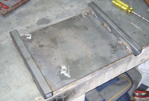
Two rails of the 1/8" x 1" square tubing were added for the motor/pump frame to sit on just to give a little extra height off the top of the tank. This was so the large pulley on the pump would clear, as well as to provide space for the check valve and other fittings.
The tank plate was then centered on the main frame and welded into place. You'll see that a few extra holes have appeared since the last picture. That's because, uh, I kind of welded the tank plate on upside down and had to make the necessary quick adjustments. It was far easier to drill a few holes than to cut out the welds and start again!
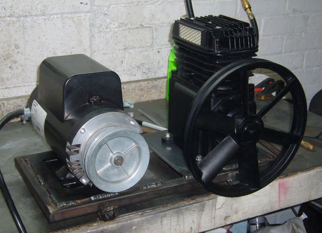
With the frame complete, you can see how the motor and pump will mount. Technically you are looking at the back of the compressor as I positioned the belt to be toward the wall and away from anyone who may be walking by. Speaking of the belt and pulleys, it just so happened that the pulley on the motor was exactly the size required to spin the pump at its rated 1400 RPM. I guess this makes sense as the motor was removed from a compressor with a 3 cylinder pump rated at 1400 RPM as well.
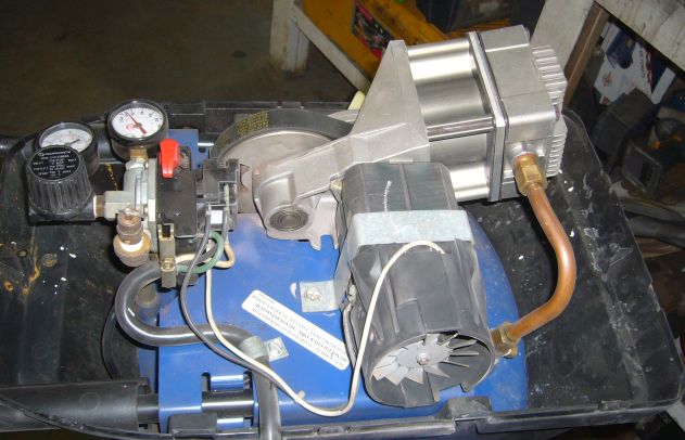
Now that the fabrication was done, the real fun can begin. After the paint on the new frame was dry, tear down of the old compressor was easy. Within about 10 minutes it was stripped down to just the tank. In the picture below of the compressor with the cover removed you can see the original pump. It's a single cylinder oil-less belt driven unit, run by a tiny motor with a laughable rating of 5 HP. Now keep the size of the actual 5 HP motor being installed in mind when considering this "5 HP" motor that plugs into a 15A 120V outlet. I'm not saying that it's a poor quality system. It's a fine compressor for home use, and it is built to that standard of needing to run only a few hours per week. At that duty cycle it would probably last the average user 15 - 20 years and C & H makes inexpensive service parts should it need a piston ring, motor, check valve, etc.
The only components that will be reused from the original compressor are the tank, regulator, and a few random fittings. The rest ended up in a box on the shelf in the event the compressor would one day be returned to stock.
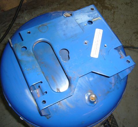
The only modification to the tank is the drilling of 4 mounting holes on the original motor/pump mounting base. And yes, the stock motor and pump assembly was only held into place by one single bolt and a metal strap.
First up, the check valve was installed on the tank. This check valve came from the blown compressor and screwed right in place of the smaller C & H valve. Looking at both valves, they were very similar, it just looked like the valve from the larger 3 cylinder compressor would flow more air. I didn't want to create a choke point so I swapped the valves. With the valve in place, the freshly painted mounting base was bolted onto the tank. Blue Loctite was used on the bolts to prevent loosening due to vibration. Into the check valve a 1/2" NPT to 1/2" compression fitting was installed. Note the 1/8" unloader port on the side of the check valve.
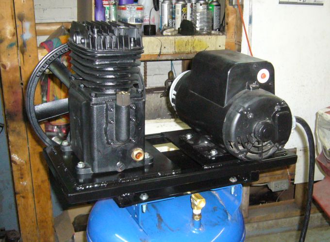
The pump and motor were bolted on next. It was a little annoying getting access to the bolts under the base but aside from that there was no drama. Both the pump and motor were left loose as the belt could not be installed (I bought the wrong size). Before the mounting base was installed I also took the opportunity to install the air outlet fitting on the tank, as it would have been very difficult to do once the base was in position due to lack of clearance. The tank has a 1/4" NPT bung so I used a 1/4" NPT male to 3/8" NPT female adapter, then a 3/8" NPT nipple, which connected to a 90 degree 3/8" NPT female-female elbow. I probably could have streamlined the fittings a little but this is what I had available at the time and the hydraulic stores were closed for the weekend.
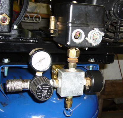
Assembly moved along quickly since all the parts were already fabricated. The pressure switch assembly (pressure switch, gauge, release valve, distro block) from the blown compressor was used as a unit and threaded into the 3/8" NPT elbow by way of a 3/8" NPT to 1/2" NPT adapter. The air regulator and associated gauge came from the C & H compressor and was adapted via a 3/8" NPT to 1/4" NPT bung. A typical quick connect air fitting allows connection to the shop air system or directly to an air hose.
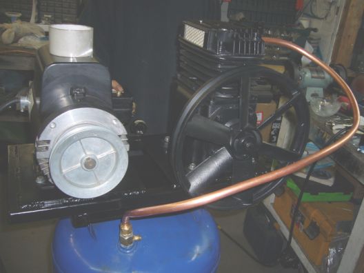
The pump connects to the check valve via a length of 1/2" copper line that was carefully bent to snake all the way around the compressor and still provide ample clearance for the belt. The pump outlet port is 3/8" NPT so it was a simple matter of using a 3/8" NPT to 1/2" compression fitting. I'm considering replacing much of that copper line with an aftercooler mounted close to the fan, if I can find one for the right price. Another possibility would be to buy 10 feet or so of copper line and coil it up behind the fan.
The last two connections to be made were the copper air line to the unloader valve, and the electrical plug to actually give this thing some juice. Unloader valves are tripped by the pressure switch and release that little bit of air trapped between the pump and the check valve. This is so that next time the electric motor starts up, the pump sees far less of a load until it actually begins to move. All good air compressors make use of an unloader valve. It's that "hissssssss...." you hear just after the pressure switch has shut off the motor. The unloader connects via 1/8" copper line (that kind of takes a fancy loop up and out of this picture) and compression fittings. The unloader line feeds under the base plate to connect to the check valve.
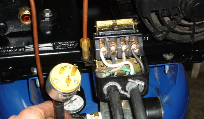
Normally one would wire a motor of this size into a service panel, but I wanted something that I could move around if necessary and easily disconnect for maintenance. I chose a NEMA 6-20R plug, mainly because I already had a long and beefy extension cord with the same connectors and because the 6-20R was rated to carry the current needed (the 5HP motor draws 22A at 240V). Plus, it is the only plug in the shop with that blade design. This prevents some idiot from plugging a 120V angle grinder or something into the outlet and getting a surprise. I wired the pressure switch according to the handy diagram on the inside cover.
And finally, the belt was installed. It actually took three tries to buy the correct belt. It seems that even with the large amount of adjustment that the motor had I was just between a 490 and 500 series V belt. Several 490 sized belts later and I found one that was just slightly long enough to fit. This happens to me every time I make something that uses a belt and you'd figure that after all these years I would have learned how to measure for a V belt.
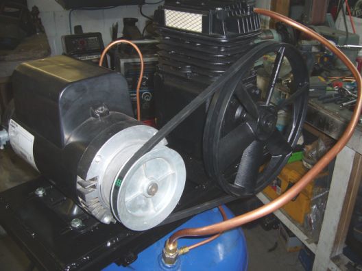
After a little fiddling with the position of the pump and motor, the belt was lined up and all the bolts were tightened down. Since the belt will stretch over time, lock washers were used instead of Loctite so that the position of the motor could be easily readjusted to maintain proper belt tension.
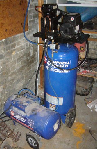 And that's it! The upgrade is now complete.
Before powering up, two things needed to take place. First, the pump was filled with 1 quart of 30-weight non-detergent compressor oil. Second, and probably most important, the pressure switch was turned to it's minimum setting.
With the pressure switch cranked down and the relief valve open, I plugged in the upgraded compressor. The was an immediate loud "BANG!", a shower of sparks from the cord I was holding, and all the lights went dark. Actually, no. What really happened was that the motor sprang to life and the pump began humming happily with complete lack of injury, death, or even serious maiming. With the compressor running and air moving, I closed the relief valve and watched on the gauge as pressure built up. Dutifully, at 80 PSI, the pressure switch tripped, the motor shut off, and the unloader briefly opened. As nothing had exploded I turned up the pressure switch another 20 PSI and waited until the motor kicked off. Then to 120 PSI, and finally to the working pressure of 150 PSI. Once I had emptied the tank and allowed it to pump up several times as a test, the compressor was carefully moved downstairs to it's home in the basement. Though a bit top heavy, the tank is quite stable on the stock wheels shows no sign of being easy to tip over. There it was connected to another 20 gallon tank via a T fitting on the bottom of the regulator/switch block. Finally, it was plugged into the shop air system, turned on, and set about to do it's job.
The difference between this and the old compressor is night and day. With the new pump and motor, the compressor no longer runs constantly while air tools are being operated. Taking only about 25 seconds to bring the tank from 100 PSI to 150 PSI, the compressor now cycles on and off during use. With the old 5 CFM pump, operation was constant during tool use and for another 5 minutes afterwards to pump the tank back up. This new pump handles both the pressure sand blaster and blast cabinet with ease. It is so nice for everyone's sanity to not have the compressor running constantly in the background. And since the new pump and motor are both heavy duty components there is no worry about running the compressor over duty cycle. Indeed, I find that I am emptying the 100 LB sand blasting pot without even thinking about where the air is coming from. By the time I've taken off my goggles, mask and put down the blasting gun, the pump has already shut off. While the new pump does require more maintenance than the old one, having both an air filter to clean and oil to change, one can only consider that a good thing.
Eventually I will get around to removing the pressure regulator from the compressor and connecting it directly to the shop air system. Then I will get additional air regulators for each connection in the shop. This will be far more convenient than having to turn down the air in the entire shop if a lower pressure is required for something like a paint gun.
You can see a video demonstration of the upgraded compressor below:
Please read the following FAQ before emailing me about this project. It may answer your question. The FAQ is updated based on common questions I receive via email.