| Home > My Projects > Digital Copper Shop Clock |
| Home > My Projects > Digital Copper Shop Clock |
Date Of Project: Spring 2009
 One thing that my shop lacked was a large wall clock, and consequently, I was always staying way too late and not making it home on time (that's my excuse, anyway). I was then quite happy to receive a Cana Kit 3-Inch Display Digital Clock kit for my birthday. After assembly, the bare clock board hung on the wall for a month or so but it was clear that it required some kind of case. I didn't just want to stick it in some generic project box nor did I want to make something out of wood which would look out of place (and I'm not a very good wood worker). For a while I had been interesting in attempting to TIG weld copper so this seemed like a perfect excuse. A nice copper case would go well with the shop environment and look like a blend of an old style "exit" sign with a modern digital display.
From the metal shop I picked a length of 1.5" x 1/8" copper bar and another length of 3" x 1/8" copper plate. In the process I was reminded that copper is not exactly the cheapest metal in the world. There was a bit of sticker shock when I compared the cost to the prices I normally pay for aluminum and steel, which was further reinforced when I got back to the shop and realized that I had slightly (OK, greatly) overestimated the amount of material needed. On my way back to the shop, I also hit the local welding supply store for some copper welding rods.
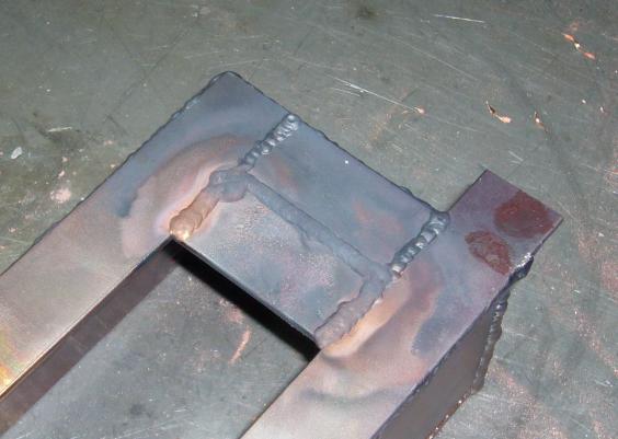
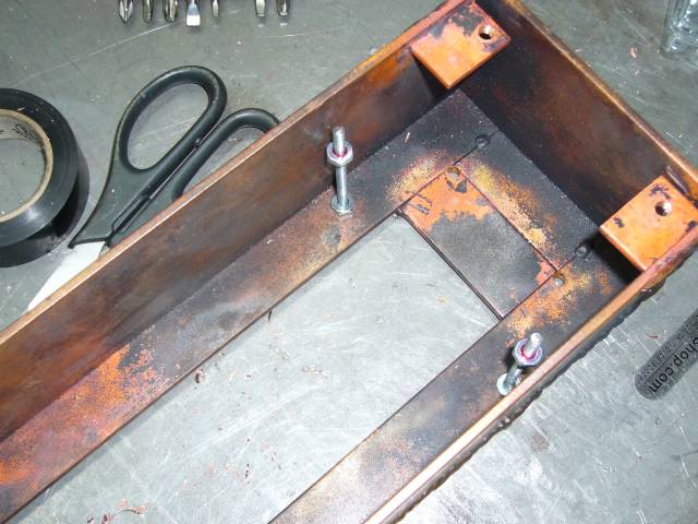
The first step in making the case was to create a base out of the 1.5" copper bar. I cut the pieces out on the band saw and laid them into position on the bench before tacking them together. This rectangle forms the base to which the clock board and transformer will mount, with the two upper "ears" used to mount the clock to the wall.
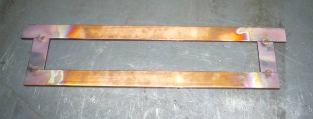
TIG welding copper is an interesting experience. The metal is extremely conductive so my 150A EconoTIG was ran wide open to make even these small tacks. It was clear that 1/8" copper is out of the capability of the machine but there was no turning back now. Once it forms a puddle, the copper seems to flow like stainless steel but pull heat away like aluminum.
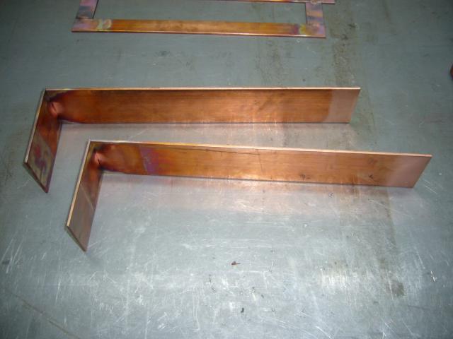
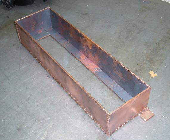
Next I cut the 3" plate and welded it into two L shaped sections which would form the sides of the case. They were made in two pieces with light tacking because I was unsure how copper would shrink during welding so I wanted to be able to manually straighten it later should that become necessary.
The sides were then tacked into place using the rear base as guide to maintain square dimensions. More and more copper being added to the case was starting to make welding very difficult due to the amount of heat required. Each one of those tacks took about 20 seconds to complete with the welder at full current.
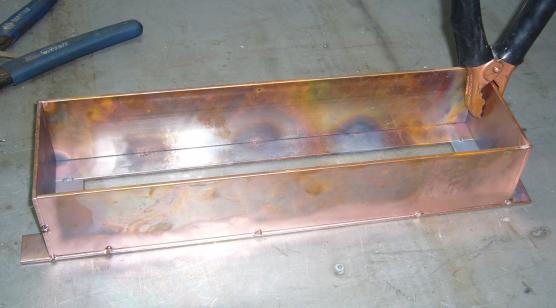
It took a considerable amount of time to weld all the seams due to having to run the welder at above its rated duty cycle. Only a few inches could be done at a time with the welder at full power to maintain enough heat to get a decent puddle. Even still, the welds were not as pretty as I would have hoped which can be directly attributed to insufficient current. Compared to aluminum and steel, copper does warp but seems to want to return to its original position instead of staying crooked. As copper cools, it forms a black oxide which flakes off later leaving bright metal underneath. In many cases I left some of the oxide in place to create an aged look.
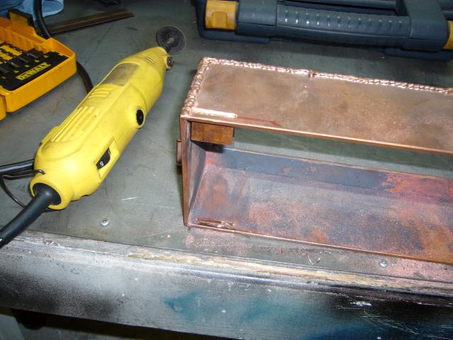
To mount the front bezel I decided to make four small tabs out of the 1.5" copper bar. Small slits in the top and bottom of the clock case were cut by first drilling a series of holes and then finished using small cutting disks on the Dremel. I left them a little tight so that the tabs would held in by friction during welding.
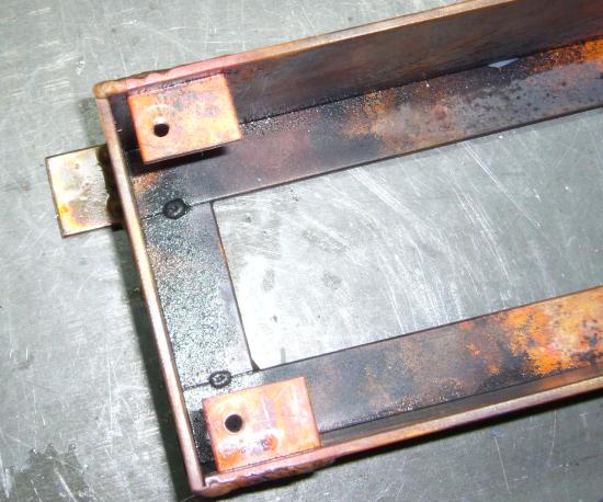
An 18V transformer is required to power the circuit, and it needed a place to mount inside the case. To accommodate it, a second strip of 1.5" bar was added to the rightmost end to provide plenty of area to drill for bolt holes. The transformer was placed to the right because on the circuit board, there is a large section to the left which contains the actual circuit. Thus the digits will be centered behind the bezel.
Holes were then drilled into each tab and tapped for M5 to fit some fancy brass bolts I picked up at Canadian Tire. Copper is an easy metal to work with but kept clogging the fine taps so I had to use a fair amount of cutting oil to flush away the metal chips.
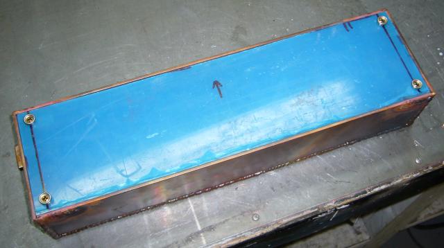
I made the bezel out of 1/4" clear Lexan that I had left over from an MP3 player project years ago. As I mentioned, the bolts securing it to the case are quite fancy. Apparently their original application is to secure a tarp via snaps, though I picked them up because they seemed to fit the general look of the clock. I left the protective blue backing on the Lexan until the last minute as to avoid scratches.
Placing the board deep within the case would greatly narrow the field of view for looking at the clock, as well as distort and dim the digits so it was necessary to make some spacers to mount the board close to the bezel. To do this, I just used a set of long machine screws. Once the screws were bolted though the base, a nut was installed near the top to support the circuit board and Loctite used to keep the nuts from rattling loose.
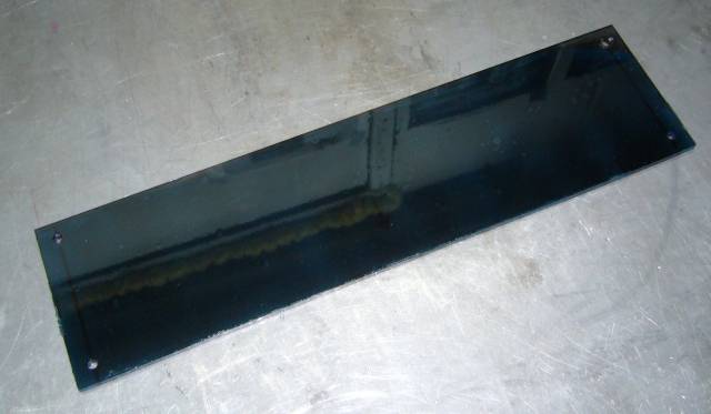
In order to hide the circuitry and to mellow out the bright LEDs, I decided to tint the Lexan a bit. To accomplish this I used tail light tinting spray that you often find kids who wear their hat sideways use on their Hondas. Since I am not a kid who wears his hat sideways, I actually had a hell of time actually finding out where to purchase the stuff. As it turns out, my local speed shop had a few cans of VHT tinting spray in the Honda isle next to the 8" exhaust tips and Altezza tail lights.
After cleaning the Lexan thoroughly with acetone and blowing off any dust with the air compressor I laid down 4 coats in alternating patterns (first horizontally, then vertically, then repeat) on the back of the panel. This left the front of the panel smooth and protected the coating on the back from scratches. I was actually impressed with this spray. It laid down smoothly and not at all blotchy as I had feared. It still won't come within 10 feet of my tail lights, though.
It was time to assemble the innards so I first mounted the transformer to the base using two small machine screws. Loctite will keep the bolts from eventually rattling loose. Over to the right of the transformer, you can see how I put a glass fuse in series with the primary and insulated it with heat shrink tubing. With a little wiggling, the main board slid into place and I secured it with bolts to the mounting screws. The power cord simply exits the open rear of the case but is secured internally to the transformer with a cable clamp.
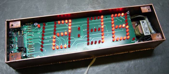
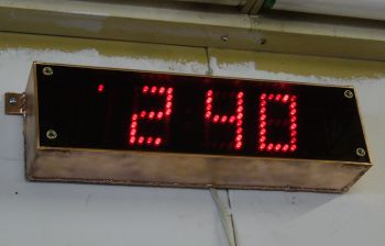
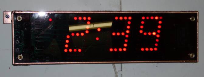
The clock was then mounted to the wall using small screws and drywall anchors. Due to the flash of the camera (I was trying to get rid of the reflection from the overhead light) you can sort of see through the bezel to the board below. In normal use the bezel hides the board and all that is visible are the red LEDs making up the digits.
I think I achieved my goal of making it look sort of like an antique exit sign or something that would have been found in an old factory. Before I mounted it to the wall I lightly went over the whole case on the wire wheel to get an uneven cleaning effect. It left the black oxide in the corners and crevices while shining up the flat areas. As the copper starts to dull a bit, it is beginning to look a bit distressed which suites the environment fine. There is one flaw in my design though; it is a real pain in the butt to set the clock. Because I miscalculated the position of the board, the setting buttons ended up underneath the bezel mounting tabs. So to set it, the bezel needs to come off and you need to poke at the buttons with a small screwdriver. Thankfully the circuit does have a 9V backup battery so the only time this actually has to be done is when the clocks change for daylight savings time.