| Home > My Projects > Satellite Internet Demonstration Trailer |
Date Of Project: Spring 2001
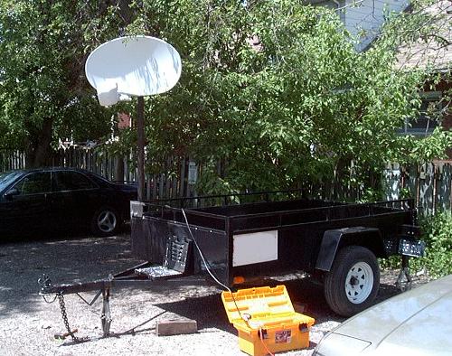
In the spring of 2001, the computer shop at which I work began selling LinCsat 2-way satellite internet systems. Basically, this system allows anyone with a clear line of site to the southwest to access the Internet anywhere in North America, at speeds comparable to DSL. The system, however, is not cheap, and businesses interested would often want a demonstration before spending the money. What we needed was a way to quickly set up a dish, point it correctly and keep it stable during demonstrations. Standard tripods would not work, as the dish must be kept as stationary as possible. Unlike a one way television system, the LinCsat dish transmits back up to space, so certain regulations must be followed. The dish cannot "wander" and interfere with other signals and the transmission path must be free of objects and people. We also needed a way to transport our displays, booths and furniture for trade shows, and a generator to run the system in areas without power. A small trailer was purchased locally and modified to provide a stabilization system and a way to mount the dish.
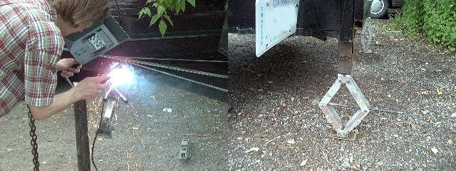
Standard automotive jacks were mounted at each rear corner and on the front tongue of the trailer to provide an easy system of stabilization and a way to level the trailer. This seemed to be the most straightforward system of keeping things stable. Since we needed to demonstrate the viability of the satellite on various terrain, it would be totally impractical to attempt to level the trailer any other way. For what it's worth, these are the lightweight aluminum jacks from the 2nd generation Mazda RX-7. I had a number of them around, so they were convenient. A bolt secured each jack to a short section of box steel, which was then welded to the trailer.
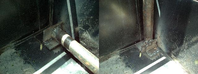
The next thing we needed was a way to mount the dish itself. The mounting pole must be level, well above head level due to RF exposure issues, and of course stable. A mast made of 2.5" diameter steel pipe was mounted in the front right corner of the trailer on a hinge. This allowed the 8 foot pole to fold flat into the trailer, keeping it out of the way for transport. To mount the hinge, plates of 5MM steel were welded to the bottom of the pole. The pole was then clamped tightly in the upright position, and the hinge was welded to the metal flange on the pole and then to the bottom of the trailer. The soft steel of the hinge made this difficult, as the pole and trailer were both made of much higher quality metal.
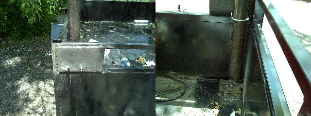
To secure the mast upright, a plate was welded to the trailer guard rail. Two holes were drilled near the bottom of the plate after the mast was checked for level. These holes allow a large U-bolt to pass through and clamp the mast to the side of the trailer. Standard wing nuts secure the U-bolt. When upright, the whole system is quite strong and the mast doesn't move at all. More complicated retention mechanisms then u-bolts were available, but the bolt is simple and it works.
After the major structural work was done, a coat of black paint was applied to all the welds, and a wooden cover installed on the front half of the trailer.
Standard setup for a demonstration is to park the trailer, then level using the jacks and several small bubble-levels. The dish is then installed on the top of the mast and rough pointed with a compass. The final pointing is done with the aid of a spectrum analyzer. Cable is then run to the satellite modems, controlled by a Compaq laptop. Normally we use 802.11b wireless to make the bridge to the customer's network for demonstration purposes since it needs no cabling. Power is supplied via a standard car battery and inverter.