How To Megasquirt Your 2nd Gen RX-7: Install CLT and IAT Sensors
Because this setup is using GM coolant and air temp sensors, a few modifications must be made to install these sensors in place of the stock sensors. The GM sensors are a 3/8" NPT pipe thread, while the factory Mazda sensors are a small metric straight thread. You'll need a 3/8" NPT tap and a 9/16" drill bit in order to make these holes. Technically, 37/64" is the proper sized drill bit for tapping to 3/8" NPT but these bits are expensive and hard to find. 9/16" is close enough and since we are tapping into aluminum, will be sufficient. By all means, if you have a 37/64" bit feel free to use it.
These instructions assume that you are tapping the water pump housing on the car. This can be easily done without having to remove the water pump and associated hardware. The throttle body inlet can be easily removed from the throttle body so it can be tapped over on a work bench.
Install Coolant Temp (CLT) Sensor
- Drain The Coolant
- Drain the coolant using the drain plug at the bottom of the rad. You don't need to totally drain the system, you just need to bring the level down a bit lower then the thermostat. However now is likely a good time to perform that coolant change you have been putting off so feel free to take the opportunity.
- Remove Water Neck and Thermostat
- Disconnect the upper rad hose from the water neck (it will still contain some coolant) and then remove the filler cap. Remove the two (or three, for S5) bolts securing the water neck to the water pump housing. Because these bolts have a tendency to corrode and become stuck, it is a good idea to use a good penetrating lube such as PB Blaster to ease removal. With the bolts removed, a few sharp whacks with your hand should fee the water neck. Now remove the thermostat. A small screwdriver or pick might be necessary to carefully pry it out.
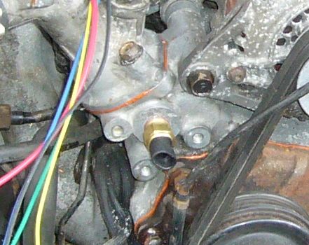
- Drill The Water Pump Housing
- Mazda has so thoughtfully supplied a small boss on the water pump housing as if they knew we needed somewhere to mount a coolant temp sensor. On the front of the housing, it is located between the bolt holes formerly used to mount the air pump. Drill out a 1/4" pilot hole in the middle of this boss. Use a good quantity of cutting oil to make a clean bore and prevent the bit from loading up with aluminum. Now enlarge the hole to 11/32" or the next most convenient size. Now, carefully use the 9/16" bit to bring the hole to it's final dimension. Go slow, use a lot of oil and make sure to keep the drill straight. Due to the length of these bits you may find it necessary to remove the radiator if you have a long drill. When you are finished, wipe away the drilling chips.
- Tap The Hole
- Thoroughly lubricate the 3/8" NPT tap and hole with cutting oil and then carefully and slowly tap out the hole. Go about half a turn at a time, reverse the tap to clear out chips, then continue on. It is very important that you keep the tap perpendicular to the surface and well lubricated. Be sure to keep all the threads clean to prevent jamming up the tap. When finished, clean the area thoroughly to remove as much of the tapping debris as you can. Clean inside the water pump housing, then finish everything up with a good soaking of brake cleaner or other solvent to remove all oil and other residue. If you have compressed air available, blow the area dry.
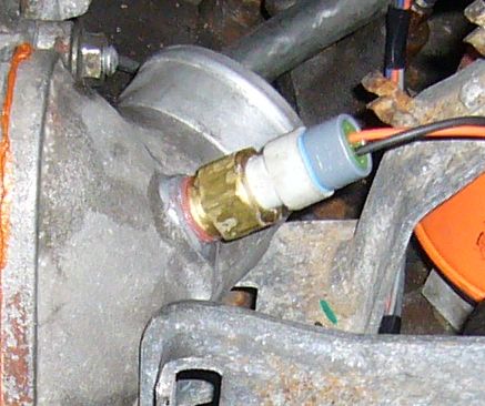
- Install The Sensor
- Coat the sensor threads with pipe dope and then screw it into the hole. Tighten the sensor until it is firmly seated. Remember, the threads are tapered so don't expect it to screw in all the way. At some point it will become very difficult to tighten the sensor and that is where you must stop. Don't be surprised if it doesn't thread in all the way. Even still, it is designed to seal on the tapered threads so don't worry and don't force it.
- Reassemble The Water Neck and Thermostat
- Insert the thermostat into the water pump housing. Using a new gasket with a skim coat of sealant on each side, reinstall the water pump neck and tighten the bolts to 14-17 FT-LBs (S4) or 5-7 FT-LBs (S5). Don't forget the anti-seize on the bolts.
- Refill The Coolant
- Now you can refill the coolant and check the new sensor for leaks. If you see a leak, snug down the sensor just a little bit more.
Install The Intake Air Temp (IAT) Sensor
Installing the IAT sensor is a lot easier mainly because there is no draining of the cooling system necessary or any disassembly past removing the throttle body inlet from the throttle body. So let's get right to it.
- Remove The Throttle Body Inlet
- Remove the two bolts holding the throttle body inlet to the throttle body and separate the two pieces. There is an o-ring in the throttle body which seals it to the inlet so make sure not to lose it. Remove the stock IAT sensor from the throttle inlet.
- Tap The Throttle Body Inlet
- With the throttle body inlet securely clamped down into a vice or to a work bench, drill out the stock IAT sensor hole with the 9/16" drill bit. Go very slowly and be very careful to keep the drill straight. The material is very thin here so you don't have any room to mushroom out the hole. Now, with plenty of cutting oil to lubricate, tap the hole to 3/8" NPT. Stop about 3/4 of the ways up the tap as you want the hole to seal tightly on the taper of the sensor without having to crank down on the sensor. Clean the throttle body completely with solvent and/or brake cleaner and blow out any remaining metal chips.
- Install The Sensor
- Put pipe dope on the sensor threads and then tighten the sensor into the hole. Because the metal is thin, be very careful not to crack or strip the hole. Just snug things down until the sensor doesn't want to turn easily any more but don't crank down on it.
- Reinstall The Throttle Body Inlet
- Clean the mating surface and put a skim coat of sealant over it, then reinstall the throttle body inlet onto the throttle body and tighten down the bolts.
Now that the sensors are installed, the rest of the wiring can take place. The next section will be a long one which covers the entire process of wiring in the ECU.
Back To Mods Page | Mail Me | Search