| Author |
 Topic Topic  |
|
konduri
Apprentece

17 Posts |
 Posted - Oct 28 2007 : 04:11:05 AM Posted - Oct 28 2007 : 04:11:05 AM


|
| But the trasistor collector was connected to the anode of LED here...Why is it so sir...Let me know the actual path of current flowing from opto coupler here... |
 |
|
|
audioguru
Nobel Prize Winner

Canada
4218 Posts |
Posted - Oct 28 2007 : 11:27:42 AM
|
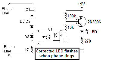
I don't see a circuit where the collector of a transistor connects to the anode of an LED.
I just noticed that the original circuit operates backwards. The relay is turned OFF when the phone rings.
My circuit copied the mistake so my LED also turns OFF when the phone rings.
I have replaced the NPN transistor that turned OFF with a PNP transistor that turns ON when the phone rings.
Download Attachment:  Corrected LED when phone rings.PNG Corrected LED when phone rings.PNG
8.09 KB
 |
|
|
|
konduri
Apprentece
17 Posts |
Posted - Oct 29 2007 : 11:48:34 AM
|
| Sir,please explain basic operation tat is taking place here which is responsible for glowing of LED when the phone ring comes...Upto optoisolator part,its clear 4 me..But from there onwards,let me know the actual opearion taking with transistor..Pls sir... |
|
|
|
audioguru
Nobel Prize Winner
Canada
4218 Posts |
Posted - Oct 29 2007 : 1:06:57 PM
|
Ask your teacher to explain how a transistor works.
When the photo-transistor turns on then it grounds the 10k resistor. Then a current flows through the 10k resistor and also flows through the base-emitter junction of the PNP transistor which turns it on.
The 100k resistor turns off the PNP transistor when the photo-transistor is turned off.
The 270 ohm resistor limits the LED current to 26mA if it is a 2V red one and the supply is 9V. |
|
|
|
konduri
Apprentece
17 Posts |
Posted - Oct 30 2007 : 08:58:25 AM
|
| ohh..thank u... |
|
|
|
konduri
Apprentece
17 Posts |
Posted - Nov 20 2007 : 03:19:55 AM
|
| sir,as u ve suggested two ways for blinkin an LED when the telephone ring comes,i ve tried both of them and being unable 2 get the o/p..Even the first ckt which is the simplest one in which the LED directly glows when the telephone ring comes in not yieldin the o/p ..DO u think tat some modifications to be made in biasing the ckt..im askin so because im a resident of India and that the telephone ring frequency and the rms value of ring voltage will vary from country 2 country as u already said... |
Edited by - konduri on Nov 20 2007 03:20:51 AM |
|
|
|
audioguru
Nobel Prize Winner
Canada
4218 Posts |
Posted - Nov 20 2007 : 08:59:32 AM
|
I don't know why the ringing voltage and current in your country are too low to light an LED.
Maybe the LED or a diode or two are connected backwards. |
|
|
|
konduri
Apprentece
17 Posts |
Posted - Jan 20 2008 : 06:48:50 AM
|
| Sir,there r 2 ways by which ring detection can be achieved as specified in this website,one using back two back-to-back zener diode connection and the other employing a rectifier circuit..are both the methods equally applicable or there are any restictions that we need 2 use one type of circuit for a particular application? Please let me know.. |
|
|
|
konduri
Apprentece
17 Posts |
Posted - Jan 20 2008 : 06:53:57 AM
|
| Im askin this because i have used the circuit as suggested by you 2 months back and i have observed that irrespective of whether ring is coming or not,the voltage that was observed at pin 5 of opto coupler was around 1.47 V.In my project,i have used the outgoing signal from pin 5 of optocoupler as a trigger for microcontroller such that the microcontroller goes on 2 execute the program dumped in it when the ring is coming.But since the trigger voltage was only 1.47 V even when the ring was coming,the program is not getting executed.So do u suggest any error in my doing resulting in this problem? |
|
|
|
audioguru
Nobel Prize Winner
Canada
4218 Posts |
Posted - Jan 20 2008 : 12:03:04 PM
|
quote:
Originally posted by konduri
Im askin this because i have used the circuit as suggested by you 2 months back and i have observed that irrespective of whether ring is coming or not,the voltage that was observed at pin 5 of opto coupler was around 1.47 V.
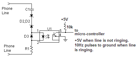
In my corrected circuit, pin 5 is at about +9V when the line is not ringing because the opto-isolator is turned off. It pulses to ground at about 10Hz when the line is ringing.
You should use a 5V supply for the opto-coupler then its output voltage will be +5V when the line is not ringing and the input resistance to your micro-controller is high.
Since your opto-isolator is not turned off when the line is not ringing then maybe you have a low resistance to ground on its output.
Or maybe your phone line has a high hum level.
Download Attachment: phone line ringing detector.PNG
6.93 KB
 |
|
|
|
konduri
Apprentece
17 Posts |
Posted - Feb 07 2008 : 1:22:40 PM
|
| Sir,so u mean to say that we have to give a ground trigger to microcontroller na...Let me also tell u abt my requirement with regard to AT89C51 microcontroller sir which im using(Earlier i thought of using PIC microcontroler)...All its microcontroller pins inherently will be at logic high state...So,when the ring comes,a ground trigger needs to be given to the microcontroller pin so that the ring can be detected...So,in this way,after 5 rings are going to b detected,i have to proceed to the rest of the program code...So,do u mean to say tat by reconfiguring the ckt as u put it earlier,can i meet my desired requirement |
Edited by - konduri on Feb 07 2008 1:41:56 PM |
|
|
|
audioguru
Nobel Prize Winner
Canada
4218 Posts |
Posted - Feb 07 2008 : 1:59:40 PM
|
i was wrong before. The output of the photo-transistor is 20Hz pulses for each ring.
The output of the photo-transistor is pulses to ground at 20Hz for each ring for my telephone system. Your telephone system might use a different frequency.
If you want to count rings then you need to integrate the 20Hz pulses like modems and answering machines do. |
|
|
|
konduri
Apprentece
17 Posts |
Posted - Feb 09 2008 : 06:37:43 AM
|
| So,u mean to say that the o/p of an optocoupler is a pulsating o/p...U r saying that we need to integrate the pulses so that we can derive the necessary trigger for microcontroller..Can u pls explain how this can b achieved? |
|
|
|
audioguru
Nobel Prize Winner
Canada
4218 Posts |
Posted - Feb 09 2008 : 10:30:55 AM
|
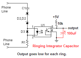
Simply add a capacitor to the output of the ringing detector circuit. The photo-transistor quickly discharges it during the 20Hz ringing pulses and the capacitor filters the pulses into a low DC voltage. Between the rings the 10k resistor slowly charges the capacitor in about 1 second.
Download Attachment: phone line ringing detector.PNG
6.52 KB
 |
|
|
|
konduri
Apprentece
17 Posts |
Posted - Feb 10 2008 : 11:28:01 AM
|
Sir,u r telling tat the in the absence of ring,the 10k resistor slowly charges the capacitor in about 1 second.So,will the o/p be high in the absence of ring? Here my objective is to achieve logic high condition in absence of ring and logic low condition when the ring comes and these logical signals should b TTL compatible...
|
|
|
|
Topic |
|