| T O P I C R E V I E W |
| enduro250 |
Posted - Jan 01 2011 : 09:04:54 AM
Hi i was reading this page
http://www.aaroncake.net/circuits/3chspec.asp
and it says
quote:
Thanks to Alterac for correcting some errors on the schematic that originally appeared on this page. Read all about it in the 3 Channel Spectrum Analyzer Project thread in the forum.
with the link http://www.aaroncake.net/forum/topic.asp?TOPIC_ID=5460
but it doesnt work! I have searched everywhere and i cant find any topics or discussion on this spectrum analyzer anywhere in the forum. if it is there somewhere (and well hidden perhaps not in an obvious board) then can someone please diredt me to it thanks. I am very keen on making this project. Are PCB's available for it from somewhere?
cheers |
| 15 L A T E S T R E P L I E S (Newest First) |
| audioguru |
Posted - Aug 17 2013 : 08:39:24 AM
If I was doing it I would re-design the filters so that NORMAL opamps can be used instead of the very odd and obsolete LM3900 IC.
The LM3915 works much better when its input has a peak detector circuit shown in its datasheet. Then every lighted LED has the same brightness.
Without peak detectors the lower level LEDs are bright and the higher level LEDs are dim and can barely be seen. |
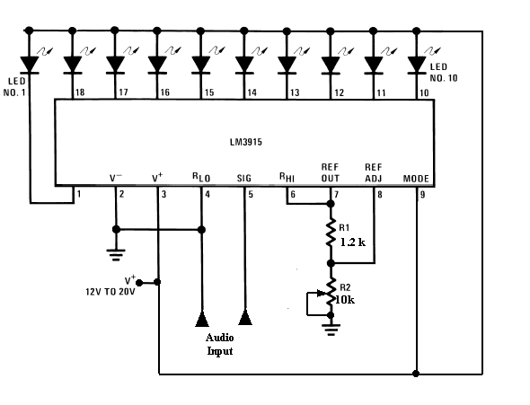
| danliska78 |
Posted - Aug 16 2013 : 5:40:36 PM
Hey guys, I am going to use my super amateur skills and novice luck to try wire this up with LM-3915s to get 10 LED per frequency channel.
If anyone would be interested to help me out I would very much appreciated it.
So basically I'm going to insert this schema to replace the AN6884
If any of you electronic wizards reading this see problem help me out here. Its going to be a lot of try and error for me since I basically have no clue of what I'm doing.
Download Attachment:  audio-level-meter-1.gif audio-level-meter-1.gif
16.04 KB |
| 5432 |
Posted - May 18 2011 : 09:47:45 AM
Can you correct the schematics? The datasheet of the AN6884, in aplication circuit shows the correct form to use the bargraph led display. But the autor says to build like the original post in site. Why if it don't work? |
| enduro250 |
Posted - Jan 17 2011 : 03:19:29 AM
Ive found places that have 6000 or more of the LM3900. Not as hard to find as i was led to believe
Just ordered 3 of the kits. i Will post up details and photos on here when they arrive and then hopefully we have 100% correct info on this kit for the future when others ask. |
| audioguru |
Posted - Jan 15 2011 : 5:45:44 PM
Most audio VU meters or spectrum analysers use the American LM3915 IC that drives 10 LEDs instead of the hard to find obsolete Japanese one that drove fewer LEDs. The LM3915 is available everywhere.
Now they are made with a micro-controller. |
| enduro250 |
Posted - Jan 15 2011 : 04:31:43 AM
Here is a video of what it probably works like
http://www.youtube.com/watch?v=psLXahAlhWw
and
http://www.youtube.com/watch?v=zYnH5-u_gxU
I reckon i would arrange the leads around the otherway so that instead of having 3 colours showing the bannds, instead have the 3 colours showign the level of each band. So maybe the bottom 3 led's in each band green, then the next led in each band yellow an dthe top led in each band red. |
| enduro250 |
Posted - Jan 14 2011 : 10:24:12 PM
Ok thanks, i will try out that kit |
| audioguru |
Posted - Jan 02 2011 : 10:18:10 PM
If you add more frequency bands then you need to re-calculate the bandwidth of the existing bands to make them narrower. The "multiple feedback bandpass filter" design is in Google but uses a "normal" quad opamp instead of the weird LM3900.
C18 is simply a supply bypass capacitor. Its value depends on how much ripple is on your power supply voltage. If your power supply already has a big filter capacitor or you are using a 12V battery then C18 can be from 10uF to 100uF.
I think the CanaKit is the same circuit. |
| enduro250 |
Posted - Jan 02 2011 : 7:22:40 PM
Ahhh thanks for that. I found the LM3900 chips. They are the same as ZL3900. Everyone was saying they are impossible to get but i found several places that have them .
Now i was reading that making a 3 band analyzer is pretty simple as shown in that diagram but once you want to add more bands then it complicates things? and you can just add on extra filters???
Also in the comments section someone asked about capacitor C18 and it has no value. Has anyone worked out what it is?
All the websites that show that diagrame are missing that one capacitor.
I compared that circuit to the canakit and although they look similar they dont appear to be the same. |
| Aaron Cake |
Posted - Jan 02 2011 : 10:57:01 AM
No, there isn't a PCB available. If I had one, would already be on the page.
Kit, you say?
http://www.canakit.com/3-channel-15-led-audio-spectrum-display-vu-meter-kit-ck109-uk109.html
Probably the same or a very similar circuit. They all seem to be about the same. |
| enduro250 |
Posted - Jan 02 2011 : 10:44:08 AM
Yeah i just wish there was a kit or something you can buy. Tf someone made a kit could make a lot of money because i have found heaps of people asking how to make them but know one really knows how to execpt for electronics experts. I would really like to make one like that little green one with rectangle LED's on You Tube as it does look simple but i bet theres a stack of stuff hidden.
If i cant find a diagrame for that then i might just have to make do with that 3 band one on here if people reckon it works. I need it to work on 12v though. |
| wasssup1990 |
Posted - Jan 02 2011 : 08:16:20 AM
I always try to avoid using someone else design in a project unless it it has been proven to work on a supplied PCB pattern. I'm talking mostly about reference designs or application notes in datasheets that give you a recommended PCB layout.
Good luck. |
| enduro250 |
Posted - Jan 02 2011 : 07:57:23 AM
I Did some more searching on this 3 channel analyzer and it shows up on a tonne of different �circuit sites�, each one lists a different source/author and you click on the authors web link and you end up going around in circles to all these different circuit sites that just seem to be coping each others info and it just appears that robots and Google ads run the sites and theres nothing personable about them. Some sites have said the diagrame is all wrong. If so that means all these sites are publishing the wrong info. Then my question is who is the original author/designer of that circuit? That�s what im trying to find out anyway.
Looking at tht 3 channel diagrame on this site it looks like you could also just link on extra banks of LEDS' and as i understand it you just need the extra little section of components for the filters.
I read somewhere that car stereos basically do this all in a couple of IC's. Aparantly you can buy spectrum analyzer chips to do this.
Yeah micro controllers are way beyond me unless its all set out as a how to with instructions.. All i need is a the parts and instructions to make one and so far this 3 channel one that keeps popping up on all these sites its the best so far i think although only 3 channels. Im just not sure about it now if people out there are saying its incorrect. I will have to check the page on this site again to see if the diagrame has been altered. |
| wasssup1990 |
Posted - Jan 02 2011 : 04:23:19 AM
Sorry I don't have enough time to offer much help but the first video you posted would most likely have components on the other side of that board. Most likely surface mount components if that's the only board the person used.
Minimum major components needed:
Micro-controller
MOSFET array ICs or specialized LED driver ICs
LEDs
A few capacitors for reducing supply ripple.
A few resistors.
Those are the major components I would use. There really isn't much to it hardware wise. If you take this approach you would obviously need to know how to program the micro-controller though. Maybe this might be a little too difficult for a newbie. I taught myself to program micro-controllers when I was 12 or 13 years old.
P.S.
Having thought about it you could possibly make one of these without the MOSFET array ICs or specialized LED driver ICs. Just make sure the micro-controller can source/sink the current needed to power your LEDs.
|
| enduro250 |
Posted - Jan 02 2011 : 02:15:56 AM
Hi Aaron, did you say a PCB IS available or dod you mean is NOT available?
Audioguru, i havent even made it or bought the parts yet. I just want to make a small simple spectrum analyser that would work on 12 volts in a car. i dont want those massive ones you see people making on you tube. I only know the basics but can assemble stuff no worries so i dont know what a opamp does but surely an equivaleny can be found.
I would really like something like this
http://www.youtube.com/watch?v=SB8_FFQSNSY&feature=related
or
http://www.youtube.com/watch?v=MHLrEekimDA
Everyone loves to show off these things but they dont wanna share any info :( I have spent basically 3 whole days looking for something like this on the web and the 3 band one on this site seems to be the best so far.
I also found this
http://www.circuit-finder.com/categories/audio/sound-level-meter/521/mini-audio-analyzer
http://users.otenet.gr/~athsam/mini_audio_analyzer.htm
but to me it doesnt look like there are several different bands. If you google 'mini audio analyzer' it comes up with 3 chips listed next to it and theres some links to a You tube video but that guys doesnt seem to be working right or is it?
So im not exactly sure about that circuit yet
The 8x10 one on You tube looks really good but surely he has got another board with more components hidden away? Otheres have asked this also in the comments section as to how hes done it with so few components and a bunch of LEDS
thanks
|
 audio-level-meter-1.gif