| Home > My Projects > 48 Volt Custom Aluminum Scooter |
| Home > My Projects > 48 Volt Custom Aluminum Scooter |
Date Of Project: Summer 2009
As much as I enjoyed riding my Electric Razor-Style Scooter, the downside of converting a push scooter to electric became fairly obvious. With a small and weak chassis, the weight of the batteries and motor (not to mention a fully grown rider) started to take its toll on the structure. The chassis required several repairs to fix cracks and broken welds over the years, and the addition of the batteries and motor left little room to stand. When the hard and solid little rear wheel wore down to the point of replacement I decided it was finally time to build a new scooter.
Unlike my previous scooters, the new scooter would be based upon a chassis built from scratch designed to fit an adult rider and properly house the electric drivetrain. No more awkward foot placement required to ride, and no mess of batteries and motor hanging off the back. This time I decided to go with a 48V battery pack, a proper PWM motor controller, and a nice set of pneumatic tires. It would be a more powerful and refined scooter compared to previous efforts.
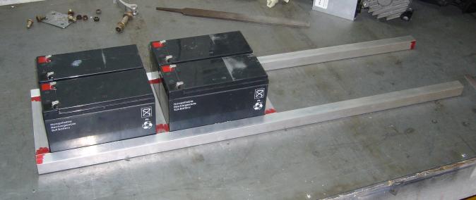
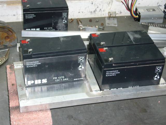
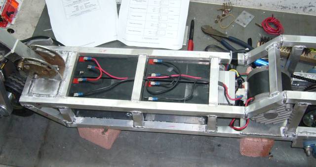
The project started with a trip to the local metal store, where I purchased about 25 feet of 3/4" 1/16th" wall square 6061 aluminum tubing. Keeping the weight down not only for speed and efficiency but also for easy transport was important so there was no question that the chassis would be made of aluminum. Once the metal was back at my shop, I laid the batteries, controller, motor and wheels out on the bench to figure out the minimum size the bottom of the chassis needed to be so the mechanical systems would actually fit. Then I measured my own riding stance and adjusted the length of the chassis accordingly for a comfortable size. With the length determined, I used the four 12V 7AH batteries to set the width and then went about cutting up the tubing on the band saw.
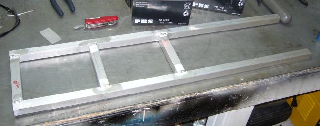
After I had figured out all the dimensions, I welded up the chassis. The aluminum was TIG welded while being held in a welding vice to keep the angles as close to 90 degrees as possible. I welded the top and bottoms of each cross member though not the inside corners to avoid interference when fitting the batteries. The chassis is designed to hug the batteries quite snugly.
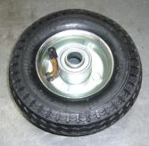 One of the issues with my previous scooter were the hard plastic wheels. While these wheels were very efficient over pavement, they were virtually useless over any other surface. They might, on a good day, handle shallow and hard packed gravel. That however was the limit of their off road capability. With this scooter, larger pneumatic wheels were a must. I was not looking at making something designed to go off road, but being able to drive over grass, dirt and in wet weather is a necessity. Not to mention the comfort factor that air filled tires have over hard plastic. From the local Princess Auto I picked up some 6" x 2" wheels, on sale I might add.
These wheels come standard with a bearing fitted but really no way to drive them. This is fine for the front wheel but since the rear wheel needs to be turned by the drive motor, the wheel needs to be able to lock to a shaft. When purchasing the wheel I also picked various things I thought would help convert the wheel into one that can be driven by a 1/2" shaft; some locking collars, a taper fit flange, some weld-on sprocket hubs and a few small diameter pulleys. My thought was that I could just hit the local bearing store for a bushing that fits inside the wheel hub to adapt it to a 1/2" shaft (the wheel bearing bore is around 1" but not quite) and the weld a collar or hub on to allow it to turn with the shaft. As it turns out, such a part doesn't exist. The 1/2" weldable hubs I purchased would almost fit into the wheel hub so I took them to the machine shop and had them turned on a lathe until they could pressed into place. Looking back, I probably could have just chucked them into a drill and spun them against sandpaper until they fit, but the machine shop was only a few dollars.
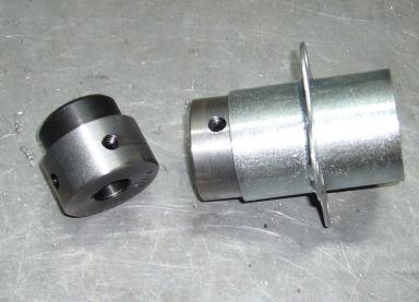
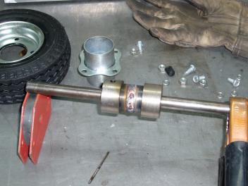
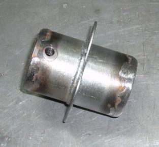
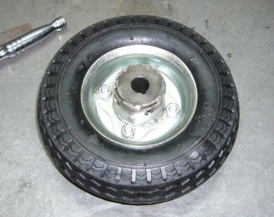
The hubs were welded together on a spare piece of 1/2" shaft in order to keep them perfectly straight. Once the shaft hubs were stuck together, they were slid into the wheel hub center so that the set screw holes could be located. Those holes were drilled (and then finessed with a Dremel until they actually lined up) and the shaft hub was then welded to the center of the wheel hub. Once everything cooled, the wheel was bolted back together.
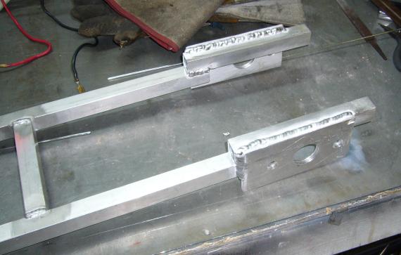
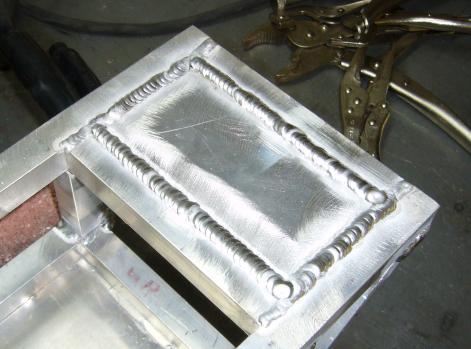
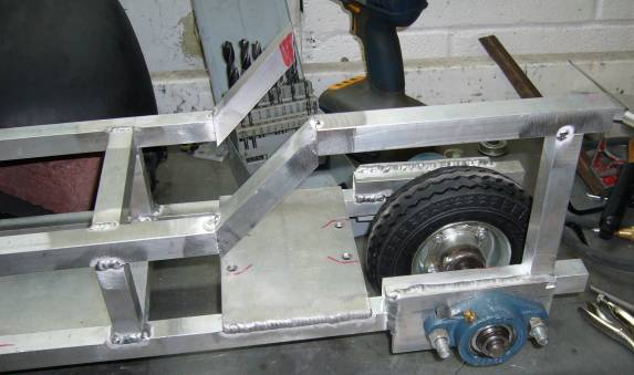
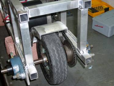
Like my previous scooter, the rear wheel of this new scooter would be mounted on a shaft which is supported by pillow block bearings. This rear end configuration is smooth, strong and easy to maintain (pillow block bearings have grease fittings). Pillow block bearings are also self-aligning so as long as the frame is straight, the bearings will line up side to side when the shaft is driven through. To mount the bearings on the rear of the frame, I made two flanges out of 1/4" aluminum plate. In order to keep the scooter reasonably close to the ground, I mounted the flanges higher by way of small frame extensions which were welded to the top of the rear frame. This allowed me to position the shaft basically level with the frame, which would not have been possible otherwise. The extensions provide plenty of welding surface for the flanges.
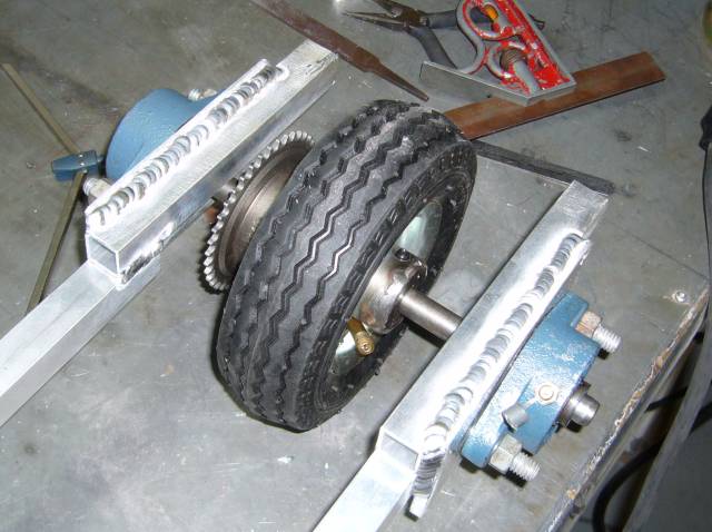
The bearings, shaft and wheel were then installed along with the drive sprocket so that the alignment could be checked. Everything fit rather well and the wheel spun smoothly.
Now that the location of the wheel was known I knew where to mount the motor. I wanted it as close to the wheel as I could reasonably make it to keep the chain short and provide plenty of space so that the motor can be adjusted forward as the chain stretched. After some measuring with the calibrated eyeball I cut a plate out from 3/16" aluminum and welded it to the frame.
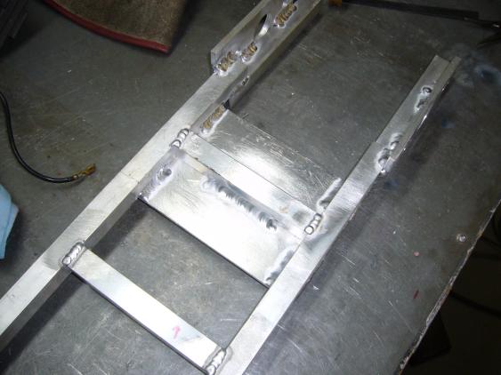
A cross member was also placed underneath the mount though I highly doubt it was necessary. The motor sprocket was lined up by eyeball and a straight edge with the rear drive sprocket and then the location was marked on the mounting plate before holes were drilled. The holes were then cut into slots, allowing the motor forward and backward adjustment to set chain tension.
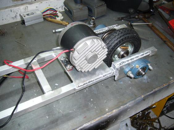
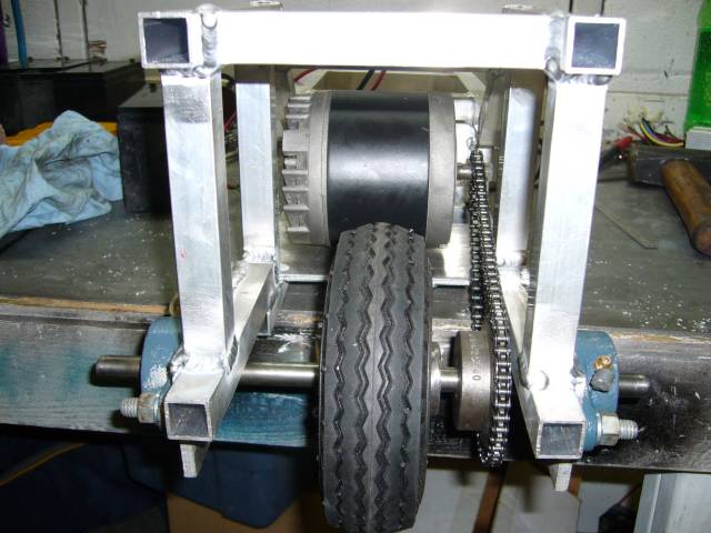
This motor is the same used in my previous scooter. I picked it up off of eBay years ago and it was sold at the time as a 36V 350W motor. It appears to be a generic made-in-China scooter motor but has ran well for many years and seems reasonably efficient. This time I'll be running it at 48V which shouldn't pose much of a problem. There is a 11 tooth sprocket mounted to the motor shaft, which is connected via #25 chain to the 30 tooth sprocket on the rear wheel. With the 6" diameter rear wheel this ratio is definitely set up for high speeds and not low speed efficiency and hill climbing. Of course, once the motor was installed I couldn't resist powering it up with 12V and checking the action of the drivetrain. At 12V, it was able to drag me across the shop floor without a front wheel, so it does have some torque.
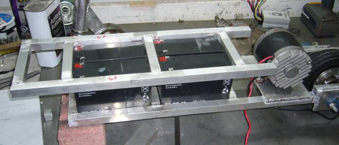
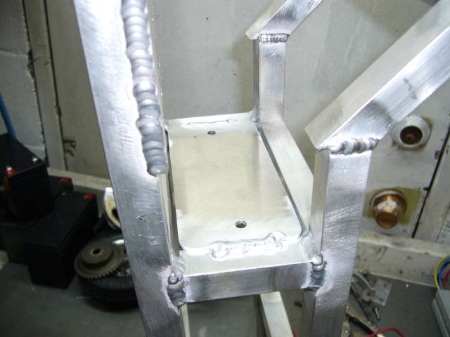
Time to move to the front of the frame. The batteries needed a tray so I welded two panels made of 1/16" aluminum to the bottom of the frame rails. I had to keep the weld current very low and weld in short bursts to avoid both warping the panels and blowing through the thin metal. Warpage was especially a concern because there was very little tolerance left for the batteries; they are intended to be a friction fit. The 48V pack is made up of four 12V 7AH lead acid batteries.
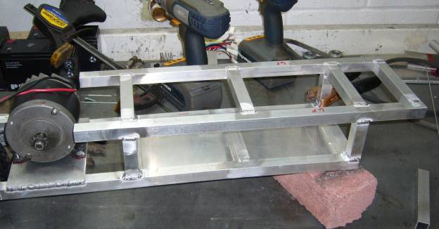
The top of the frame was made using many of the same measurements as the bottom so that it would fit around the top of the batteries. Extending the front a little made room for the steering column to mount and the rear of the frame ended just before the motor.
Measuring the height of the batteries, the top frame was positioned so it sat just above the level of the batteries. This allows room for the wiring to reach the terminals underneath the deck of the scooter. Each leg was first welded to the top frame using the welding vice to keep them straight, and then the whole top assembly was welded to the bottom. The fitment of the top was a little off in a few places but considering these are hand made parts, the tolerances were acceptable.
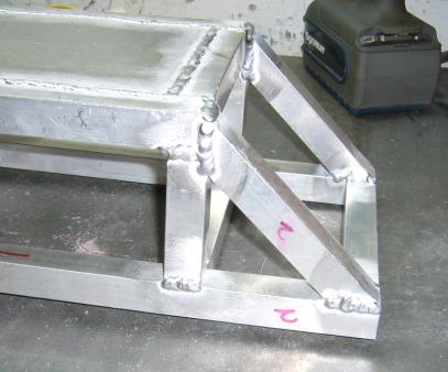
A little more support was needed on the front end, so to firm up the structure, two angled supports were welded between the front overhang and the lower frame. The braces were made simply by laying some offcuts against the area and then tracing the angles at which they needed to be cut. The cuts were made on the band saw and then filed to fit.
The mounting plate for the front end was made out of 1/4" aluminum cut to fit tightly into the front of the frame.
Next up was mounting the actual front end. I started with the front steering and fork assembly salvaged from my previous scooter. It already contained a mechanism for folding down as well as a collapsible steering column and detachable handle bars so it seemed like a good place to start instead of fabricating my own from scratch. I drilled the holes, leaving a little wiggle room for adjustment and then test mounted the front end.
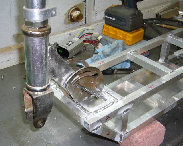
The stock forks, designed for the original tiny plastic wheels, were of no use for the much larger pneumatic wheels I was using. They were trimmed off with a cutting wheel with just enough material left to weld on a new set of flanges. I made these by cutting one side off of some 2.5" square steel tubing. A mockup of the new fork assembly was held together by Vice Grips and friction so that I could decide on the front ride hight and check to make sure there were no clearance issues. I set the front end up so that it was about 1/4" lower then the rear. Any more or less drop in the front would have looked weird.
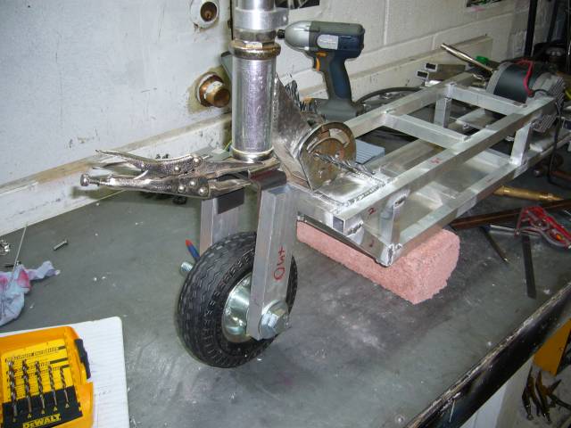
It took a trip to the local fastener store to get the huge 5/8" bolt to secure the front wheel. I'm thinking at this point to get some thick walled 5/8" OD tubing and replace the bolt as it is quite heavy. A flange welded to one side and a cotter pin on the other side would secure the tubing.
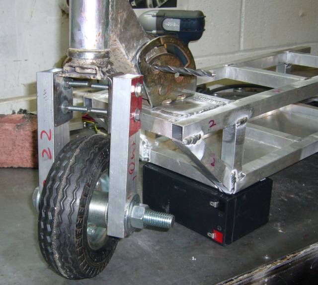
The final front end assembly started with welding the new mounting flanges for the forks. The MIG welder was out of the shop at that exact moment and I didn't have any steel rod for the TIG so I had to use the flux core welder. A pretty weld process, flux core is not but in reality it turned out to be the correct choice as the steel used on the front forks was of dubious quality. It probably would have only MIG'ed acceptably and TIG'ed rather poorly. Once the welds cooled, I measured up and drilled the holes for the M6 bolts which mount the wheel uprights (made of 3/4" x 1 3/4" aluminum tubing) to the forks. For the final assembly all the bolts would be trimmed to a more appropriate length and red Loctite used on the threads.
With the front end complete I went to work finishing up the rear. I spent about half an hour deciding exactly how the rear would be shaped with the two top contenders being a simple increase in deck hight or a wild kick up (picture the fins on an old Cadillac). Ultimately, taste and functionality won over outlandish style so the deck height was increased to make room for the motor and rear wheel.
I started by taking some eyeball measurements of the height of the motor and then decided how much height I needed for the deck. Once that was determined, I cut two pieces of tubing to length, each angled at 45 degrees. A gradual slope to the higher rear deck would be far more functional and aesthetically pleasing then a vertical wall. After that, the rest of the rear section was pieced together by first tacking on the horizontal piece, levelling it out to the bottom of the frame, and then tacking in the rear vertical support. The other side was basically the same with a few minor adjustments to compensate for some slight dimensional differences.
Between the motor and batteries was the perfect spot for the motor controller. A simple plate was made of 1/8" aluminum and drilled to match the mounting flanges on the controller. After that, it was welded in place. Notice the fancy radiused corners. They're there mainly to clear the thickness of the welds which attach the vertical upper frame tubes.
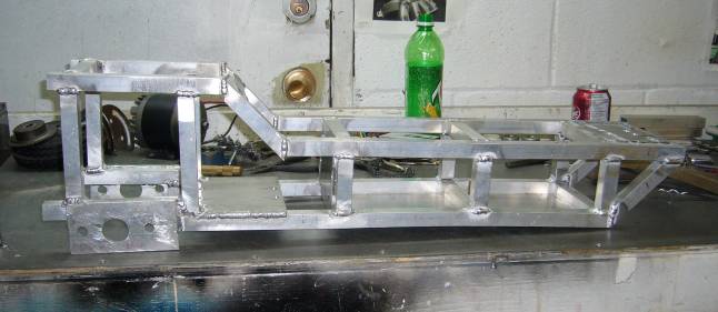
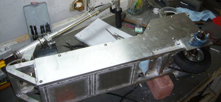
At that point the frame was nearly finished. Just a few more crossmembers were added to the rear and any unwelded areas were then welded. There was no angle from which I could take this picture that didn't make the frame look warped, but considering all the welding and hand fabrication, it is quite straight. It is actually quite light as well. I didn't really weigh it but it was comfortable to dangle from one finger.
Now that the chassis was complete the final assembly could start. Beginning from the rear, I installed the rear wheel assembly including bearings, drive shaft, sprocket and of course, the wheel itself. The motor went in next and at the same time I measured and cut the chain. While it would be nice to have a chain breaker tool, I cut chain so rarely that I can't justify the investment. The cutting wheel on the Dremel is however an acceptable substitute. One just needs to be careful not to damage adjoining links.
A small bit of unanticipated interference was created by the motor mounting plate. It wanted to occupy the same space as that taken up by the bottom run of chain. A simple notch in the mounting plate took care of that issue. As this was the final assembly, all the set screws in used in the rear got a coating of blue Loctite to prevent them from vibrating loose. On any kind of rotating assembly, any hardware not Loctite'd will inevitably end up loose.
The batteries and wiring was next. The batteries fit very snugly into place, requiring some slight tapping with a persuasion hammer. While this means that they don't require a retaining mechanism, it does mean that they may be a real problem to remove after they have worn down and bloated a little. Anyone who has removed a bad set of batteries from certain model UPSs knows exactly what I am talking about here. Before the batteries were installed I drilled some holes in the bottom of the battery tray not only for drainage but to allow for a poking implement to aid in future removal.
The wires run through slots cut in the horizontal tubing. They were made using the cutting wheel on the Dremel and then finished off with a hand file. Sections of double-walled adhesive-lined heat shrink tubing protect the wires from damage due to rubbing on the edges of the tubing. As I mentioned previously, the batteries are wired in series for a total of 48V at 7Ah.
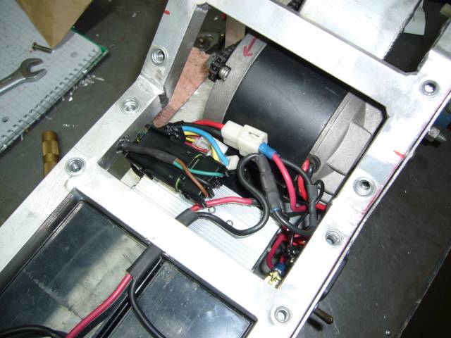
I couldn't resist also temporarily wiring up the controller and motor to test the whole electrical system for the first time. The twist grip throttle control was also connected at this point. It is a hall sensor type throttle, which oddly fit the stock Razor handle bars without any modification at all.
The first time the batteries were connected to the controller I was given quite a fright by the large spark and accompanying "BANG!". Thinking I had just let the magic smoke out of the controller, I checked my wiring to make sure nothing was backwards. Finding no faults, I crossed my fingers and turned the throttle control slightly. The controller whined and the motor turned! It seems that the big inrush current was just charging the input capacitors in the controller.
Of course, at this point I also couldn't much resist taking it for a quick spin. After a few laps around the block I was quite happy with how it performed. According to the GPS on my Blackberry, top speed is 30 KM/H which is completely respectable. A bit lower then I would have liked, but plenty fast when you are behind the handle bars. No range testing was done because the top deck was not yet installed. Also, there was another one of those unanticipated problems; road debris was being thrown up by the rear wheel onto the motor.
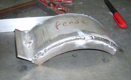
To solve the road debris issue, I needed a rear fender. I had some 8" diameter 1/8" aluminum tubing in the shop left over from another project which turned out to be the perfect size. So I cut a section out of this tubing to form the top area of the fender. The sides were also made of 1/8" plate and formed by first tracing the fender, then a compass was used to trace an identical line about 3/4" from the first. It was all welded together with a flange on the bottom so that it could be bolted to the two rear motor mounting bolts.
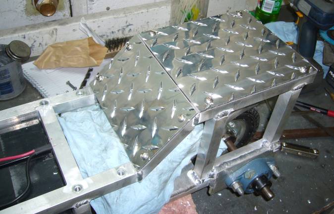
In my mind, there was only one choice in materials for the scooter deck; polished aluminum diamond plate. This stuff is not cheap, but nevertheless I picked up some 1/8" diamond plate from the local metal store. The deck is constructed in three pieces with the main section being the one most used when riding.
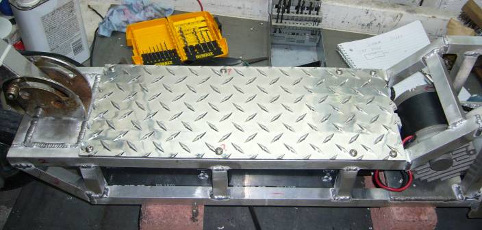
The rear of the deck is made up of two pieces, one for the angled area and one for the flat area. Each deck plate is secured to the scooter chassis using stainless M6 Allen head bolts. Nutserts (also called "rivnuts") are inserted into the chassis to provide threads for the bolts. If you are not familiar with rivnuts, picture a blind (or "pop") rivet but with the center mandrel replaced by a threaded section. They are a great way to quickly add threads to a blind hole without having to weld in a bung or break out the tap and die set.
Next up were the side panels. I first traced out a template using some cardboard so that I could fine tune the shape easily. It is often much easier to make panels like this first in cardboard, tweak them to fit and then cut them out of metal once you have the shape in its final form. The sides were made from 1/6" aluminum and like the deck, secured using nutserts.
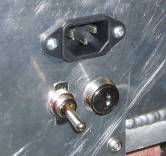 The right side panel also houses the charge port, main power switch and "ignition" key switch. There is just enough room between the controller and the motor for these three items and the associated wiring. While the charge port may look as if it accepts a standard 120V/220V computer power cord, the connector is actually used for the 48V made in China charger. It just so happens that the charge cable uses the same connector as almost all computer power supplies. The key switch is an important addition that I wish I had on my previous scooter. More then once, some ill-behaved kid had snatched up the scooter when I left it unattended and proceeded to almost seriously injure themselves. Of course, parents need to control their offspring but it was me who received the verbal abuse from those parents-of-the-year for leaving something so unsafe around, instead of the apology I deserved and the smack upside the head deserved by the child. But, I digress. This time the key switch means that I am the only one which can operate the scooter. The main power switch cuts all power to the controller so that it will not slowly drain the batteries when the scooter is not in use. A little red Loctite prevents the switches and socket from becoming loose due to vibrations.
At this point, the wiring was also finalized. I fished the throttle control through the right upper frame tubing to protect it and also provide a neat appearance. The cheap connectors on the controller and throttle were replaced by WeatherPack connectors while standard spade connectors were used to connect the batteries and motor. Heat shrink tubing insulates and secures all of the spade connectors so that they do not come apart or rub the chassis.
With all the construction done, all that remained was to install the deck and sides, then snug up any remaining bolts, grease up the chain and put some air in the tires.
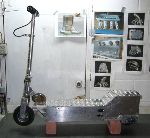
The completed scooter is shown below with the steering column collapsed.
After all this work I am extremely pleased how the scooter came out. It has a much more manufactured look and feel then any of my other scooters and it performs like it was designed for the purpose instead of being adapted.
Performance wise, maximum speed is about 30 KM/H. I was worried that the 3:1 ratio and 6" tire would be far too soft for decent hill climbing but the thing takes hills without even breaking a sweat. The ride is comfortable due to the pneumatic tires and the scooter handles quite well. With the lower center of gravity it is very stable and will handle rough terrain with few issues. Range is about 15KM, at which point the batteries are past their safe discharge threshold. Usable range then is about 10KM which is more then enough for its intended purpose. It will charge from dead in about 3 hours using the no-name China charger. It did turn out a little heavier then I would have wanted, however. Even with the aluminum chassis, the battery and motor weight makes up most of the mass with the scooter tipping the scales at 51.6 LBs.
Please read the following FAQ before emailing me about this project. It may answer your question. The FAQ is updated based on common questions I receive via email.