How To Rebuild The Metering Oil Pump
The metering oil pump is generally a very reliable device. It's almost immune from any mechanical failure, but as these pumps begin to show their age, they are beginning to leak. The culprit is the o-rings that are used to seal the ends of the pump body and the flow adjustment shaft. As is common with age, the o-rings dry out and allow oil to pass. The result is an oil leak from one or both metal end covers on the pump body, or a seepage from around the shaft. Fortunately, this is easy to correct without having to purchase a new and expensive pump.
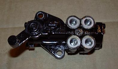
This document details rebuilding the mechanical metering oil pump found on all Mazda rotary engines until 1989. For 1989, Mazda switched to an electronic metering oil pump which is not as easily rebuildable (and generally fails electrically before it leaks). Most of the metering oil pumps are the same internally with a few changes in the case and mounting. As an example, 1st gen pump have only two oil outlets, while 2nd gen pumps have 4. The pump used in this article is from a 1986 S4 NA. The procedure is generally the same for all pumps but be aware that yours may not match these pictures exactly.
Parts Required
- Carburetor Cleaner/Brake Cleaner and/or Solvent Tank/Parts Washer
- Good Stiff Bristle Brush
- 2 Viton O Rings, 11/16" x 1/16" (For Pump Body Ends)
- 2 Viton O Rings, 1/4" x 1/16" (For Pump Flow Adjustment Shaft)
The o-rings will be available at your local hydraulic store. It's likely they will be a special order item only available in quantity, but they are cheap enough that even the minimum quantity (15, 30, 50) will be only a few dollars. Make sure to get Viton o-rings. Regular rubber o-rings sold at hardware stores will be turned to goo by the engine oil. For readers in the US, McMaster-Carr has a wide selection of o-rings.
- Step 1 - Remove The Metering Oil Pump From The Car
- The pump itself is easy to remove, but access can be limited depending on what accessories are installed on the engine. It helps a lot to remove the air pump and fan shroud. The metering oil lines come off with a 10MM socket but be very careful not to crack them. They become very brittle with age and are easily damaged. If you do damage a line, you might as well bite the bullet and order all of the lines from Mazda. Since the upper intake has to come off to access the nozzles, it makes sense to replace all the lines at once. After the lines are removed, take the small locking pin out of the control rod and slide the rod up and out of the lever. Now the pump is easily removed by loosening the 10MM bolts holding it to the front cover, wiggling it a little, and sliding it off the engine. Put the bolts and pin aside so they don't get lost.
- Step 2 - Clean Pump Externally
- Using your carb/brake cleaner or your parts washer and the stiff bristle brush, try and clean as much crud off the exterior of the pump as possible. This will make it much easier to work with. With a knife or pick, clean the heads of the 4 Phillips screws that secure the end plates. What you should end up with is a fairly clean pump, ready to be disassembled.
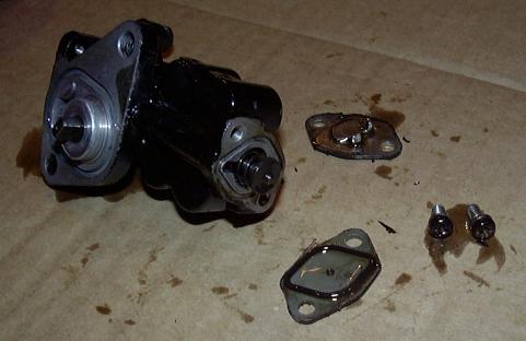
- Step 3 - Remove The End Plates
- Using a Phillips screwdriver, remove the screws that hold the end plates onto the pump body. If they are stuck, try using a 1/4" drive Phillips bit in a ratchet. If that fails, an impact screwdriver will certainly do the job. Additionally, sometimes a flat head is the way to go depending on how badly damaged the head of the screw is. Pry the plates off with a knife or small screwdriver.
- Step 4 - Remove Lever and Drive Gear
- With the end plates removed, the piston, adjustment lever and drive gear can all be removed. The piston is spring loaded and should pop out easily. With a bit of wiggling and rotation, the adjustment lever should slide out. The drive gear and shaft will probably require as set of pliers and don't be surprised if the large aluminum bushing slides out as well.
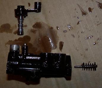
Take very special note as to how the return spring on the adjustment shaft assembly is oriented so you can put it back together properly later on.
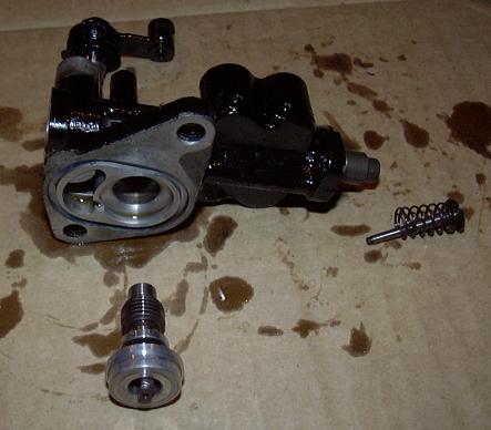
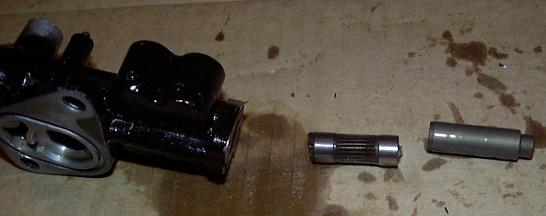
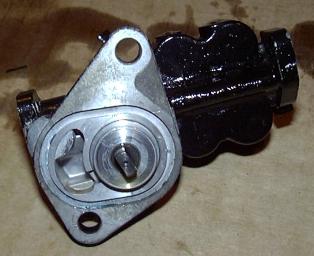
- Step 5 - Remove Center Shaft
- The center shaft should now slide out of the end of the pump body. If it's stuck a magnet will remove it without too much effort. In some cases, if the pump body is very worn, it may get hung up on a built up ridge of metal. If this is the case, discard and replace the entire pump as it's past it's useful life.
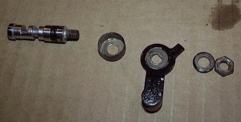
- Step 6 - Disassemble Flow Adjustment Lever
- Disassembly of the flow adjustment lever is next. Lightly clamp the arm into a vice and then use a socket to remove the bolt. It is important that the bolt be clean and free from corrosion to avoid having to place undue stress on the arm during removal. Penetrating oil helps greatly to loosen it up. With the nut removed, the lock washer, arm and cup should slide off of the shaft.
- Step 7 - Clean Everything
- Now that the pump is fully disassembled, it should be thoroughly cleaned with your brake/carb cleaner or in your parts washer. Remove all the grime from every assembly and make sure that no grit or varnish remains inside the pump body. If the crud is especially bad, the pump can be soaked overnight is solvent without damage since all rubber is going to be replaced. A good, strong carb cleaner will certainly do the job.
Once the pump is clean, blow it dry with compressed air making sure to clear out all the internal passages. If you don't have compressed air, brake cleaner works well and will not leave a residue. Just make sure that no junk remains in the pump at this point.
Make sure to also clean the internal parts of the pump including the drive shaft, center shaft, etc.
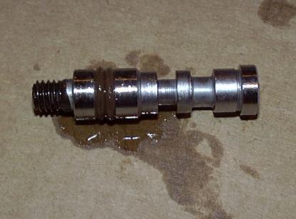
- Step 8 - Replace Shaft O-Ring
- Remove the old o-ring from the adjustment shaft using a razor blade or sharp knife. There isn't much danger in nicking the shaft but you should be careful nonetheless. Soak two of your 1/4" o-rings in engine oil, and then carefully roll them onto the shaft to replace the single OEM ring.
- Step 9 - Reassemble Pump Internals
- Coat all the pump internals with engine oil. Insert the flow adjustment shaft through the top of the pump, twisting slightly to avoid pinching the o-rings. It may take a bit of oil to allow it to be pushed through as the new o-rings are a bit thicker then the old ones.
Insert the two pieces of the center shaft. The geared section goes in first, and then the smooth section follows. Notice that there is a key on the geared section and a matching keyway on the straight section. As you can probably guess, they fit together. Make sure to line them up when inserting the smooth section of the shaft and then wiggle it back and forth to seat the key. Refer to the image from Step 5, reproduced below, for details:
Now insert the driveshaft from below into the pump body. You may need to rotate it to mesh the teeth with the center shaft.
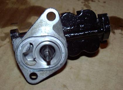
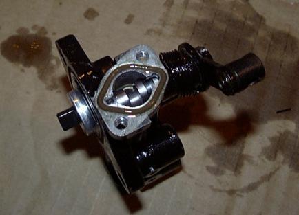
- Step 10 - Install Driveshaft Support Flange
- Install the driveshaft support flange over the shaft and seat it in the pump body. You may need to do this slowly as air will tend to get trapped behind it and push it back out as if it was spring loaded. Don't worry about replacing the o-ring on the flange as it only seals the pump internally and thus cannot cause any leaks.
- Step 11 - Reinstall The Flow Adjustment Lever
- Hold the pump body so that the metering oil tube banjo bolt threads are on the right and the adjustment shaft points straight up. Slide the spring over the adjustment shaft boss so that the hook points away from you and the straight end butts up against the stopper. Rotate the adjustment shaft so that when looking through the end of the pump closest to the shaft, the cam points towards the other end of the pump. Install the cup over the spring, then install the lever onto the shaft so that it points towards the shaft end of the pump (it should not point at the banjo bolt threads). Install the lock washer and then the nut. Carefully tighten down the nut.
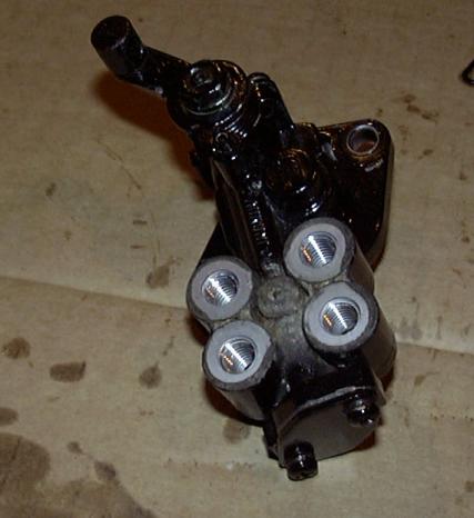
- Step 12 - Install End Plate O-Rings
- Soak the 11/16" o-rings in oil and install them into the grooves at each end of the pump body.
- Step 13 - Reinstall End Plates
- Now simply reinstall the end plates and tighten up the screws. Make sure to place the spring loaded piston back into the banjo bolt end before you install the plate. The end plate with the small tang on it goes on the lever end of the pump. The new o-rings are a bit thick so the plates may not sit completely flush immediately but will work in over time. At this point, rebuilding of the pump is complete. Rotate the driveshaft and move the lever around to make sure things move slowly and don't stick. While the adjustment shaft may be a bit stiff due to the new o-rings, it should return to it's neutral position under spring pressure. If some part of the pump does not operate, disassemble the pump to determine the problem.
- Step 14 - Reinstall The Pump On The Engine
- If necessary, place a new o-ring into the engine flange on the pump body. Rotate the driveshaft do the key lines up with the drive key in the front cover and put the pump into place. You may need to rotate the pump side to side a little. Now install the mounting bolts and tighten them to 6-8 Ft-LBs. Reinstall the metering oil line banjo bolts using new copper crush washers. Now place the control rod into the lever and reinstall the pin. Also reinstall any engine accessories removed to access the pump.
Notes
- It is very important that you keep the pump clean and well lubricated during reassembly. If there is any dirt inside the pump it will find it's way into the metering oil nozzles and clog them up.
Back To Tech Page | Mail Me | Search |