| Home > RX-7 > My RX-7 > Project Tina > Project Tina, April 30th, 2010: TII Oil Pump and Transmission Installation, Catch Can, MOP Removal, Intercooler Improvements |
| Home > RX-7 > My RX-7 > Project Tina > Project Tina, April 30th, 2010: TII Oil Pump and Transmission Installation, Catch Can, MOP Removal, Intercooler Improvements |
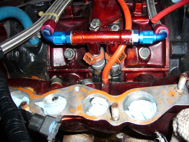
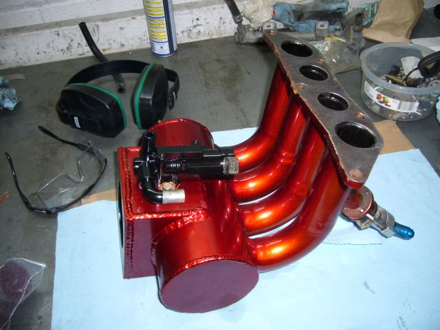
I next pulled the upper intake manifold so I could gain access to the top of the engine. The bolts shown below will be used to plug the stock metering oil holes. I forget what thread they are exactly as I just took my metering oil nozzles to the fastener store and picked up some bolts to match, then I trimmed the length down fit the engine.
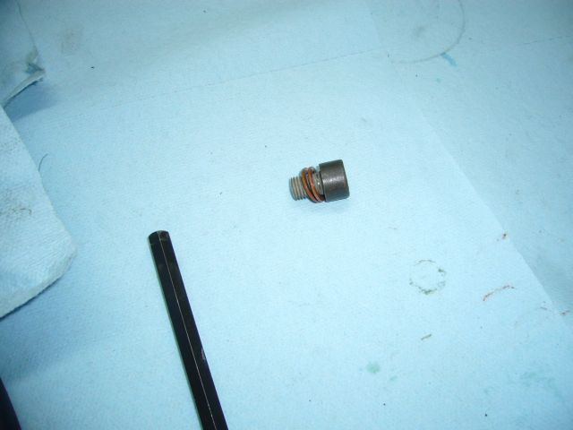
The bolts were then installed with copper crush washers and pipe dope to seal them up.
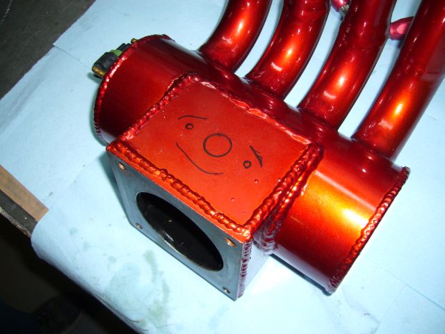
When I originally built my upper intake manifold and purchased my Microtech LT8s, I figured the car would be idling high enough that I wouldn't need a BAC valve. Oh, how wrong I was. It is always nice to have a BAC valve. Always. I was really missing the high cold idle and proper warm idle regulation that a BAC can provide so I sent my Microtech off to Australia to have the BAC control option fitted and set about adding a BAC valve to my custom manifold. I decided to mount the BAC valve to the bottom of the throttle body plenum, mainly because that as the only place I could actually fit it.
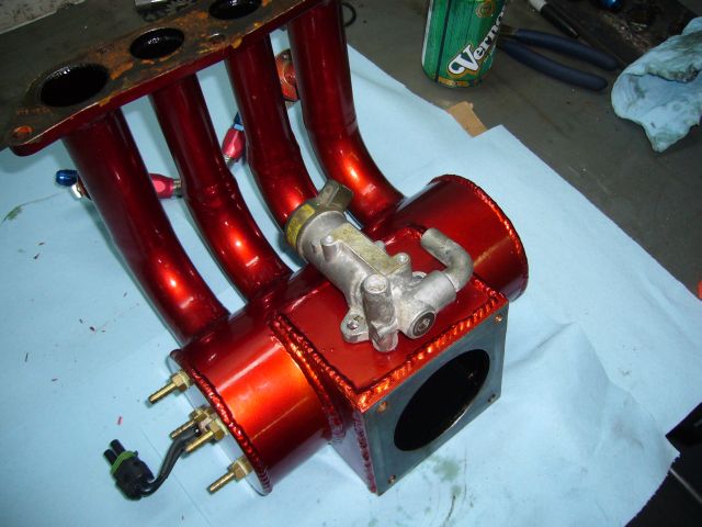
The marker traces for the mounting location and bolt holes look like a friendly happy face with a comically large nose.
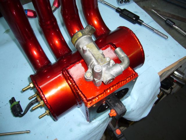
After making all the necessary holes, the BAC was bolted in place for a test fit. There was just enough metal thickness on the floor of the intake manifold to tap the holes for fine threaded M6 bolts.
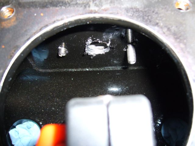
Here's a rough interior view of the main air feed hole, and the two bolt holes. The bolts used are just temporary and have not yet been shortened. Once fitment was proven, the BAC valve was painted black.
While the BAC work was being done, my custom TII transmission to NA rear end drive shaft arrived. The driveline shop (London Driveline Technology) built it out of my old shaft with a new front yolk and big Dodge truck U-joints. For comparison, a standard S4 NA driveshaft is above it on the bench.
![]()
The freshly painted BAC was then mounted on the upper intake manifold. And here is where things begin to suck...
About this time I learned from the Microtech dealer in Australia that my LT8s was "too old" to be upgraded for BAC control. Funny, Microtech promised all of us LT8s owners that our ECUs would always be upgradable. I guess that is not entirely true, and is yet another broken promise from the same company that has still not given us the promised save to disk and software upgrades that we have all been assured are only "months away" for the past 6 years. So at this point, the BAC I just installed on my intake manifold is decoration until I can figure out how to make it functional...perhaps with a Megasquirt?
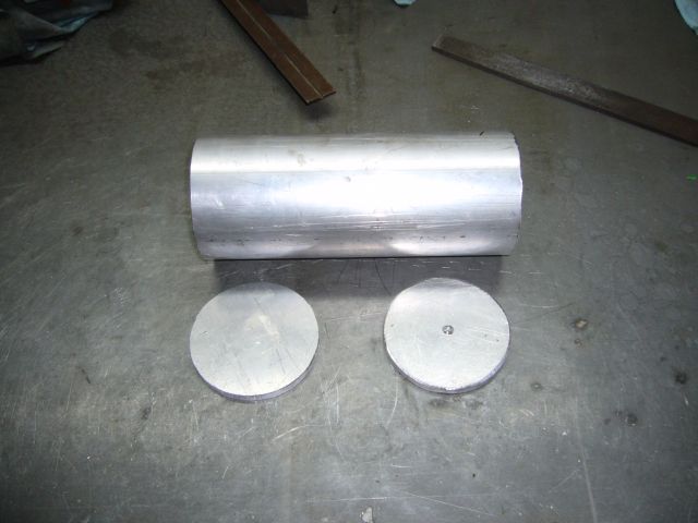
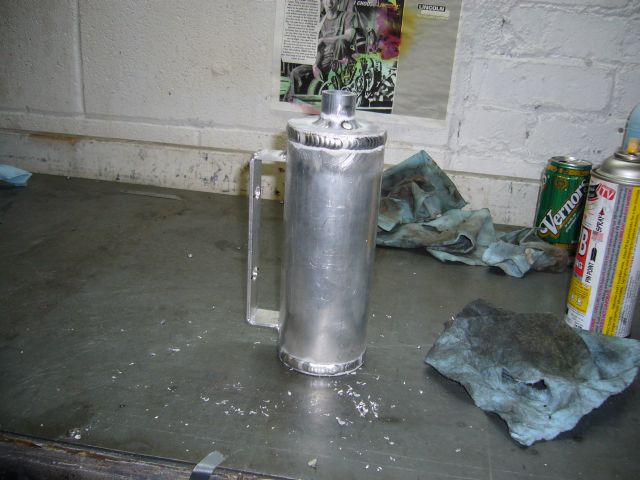
For a while I have needed a proper oil catch can. I've had an issue with blowby where oil will be forced into the PCV related vacuum hoses under boost, then sucked into the intake manifold when the throttle closes. Occasionally this will produce a cloud of smoke. So two years ago I installed a hastily made catch can that I assembled out of some plumbing pipe, which for the most part did the job. But it was too small and mounted in an odd spot (beside the charcoal canister) so sometimes, oil would get sucked out of it. A new can needed to be installed closer to the oil nipples on the center iron. I started fabricating a new can by first cutting a length of 2.5" aluminum tubing (about 7 - 8" long, I eyeballed it) and then cutting some end caps out of 3/16" aluminum.
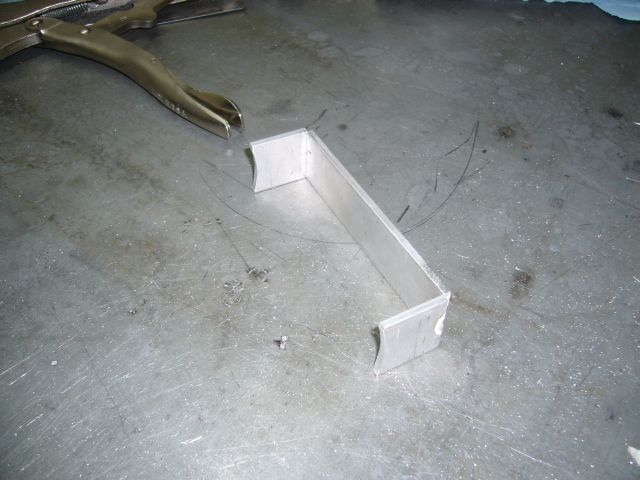
The caps were then welded to the can. Notice the relief hole I drilled in the picture above so that I was not welding a sealed cylinder. Any amount of solvent or fumes in the tubing could cause it to burst while welding if it is sealed.
The mounting bracket was made out of some 1/8" x 1.5" bar stock I had lying around. The ends were shaped on the belt sander which happened to have exactly the same radius on it's drive drum as the catch can has.
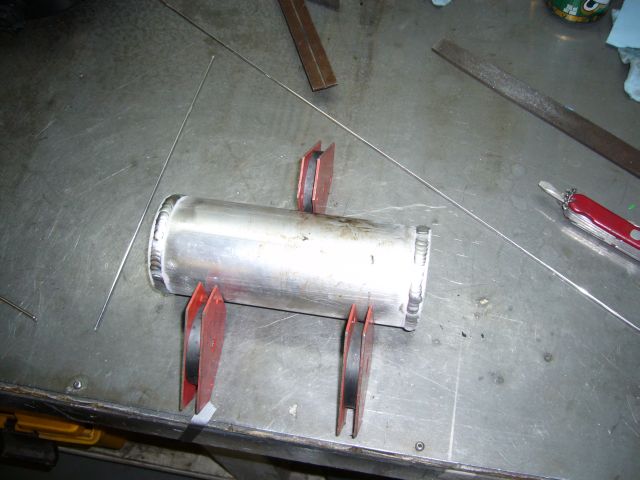
Before I welded the bracket to the can, it was tested on the engine. It mounts to the factory power steering/AC bracket holes. The factory studs were removed and bolts used instead.
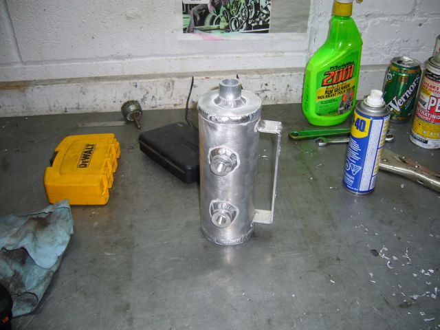
To make the top fitting on which to clamp the breather filter I just cut a short length of 1" SCH10 aluminum piping. This is actually the same pipe I used for my strut bar two years ago. The mounting bracket was welded on at the same time.
I cut some 1" pieces of 1" round aluminum bar stock to make the bungs for the fittings. They were welded in place, then drilled and tapped for 1/4" NPT. The bottom end cap was also tapped for 1/4" NPT to provide a location for the drain valve.
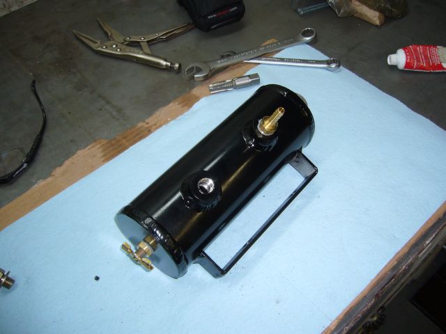
After the can was painted, all the fittings were installed. Note that the bottom bung isn't being used right now, so before I mounted the can I just put in a 1/4" pipe plug. It's always nice to have extra bung available for future use.
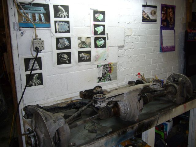
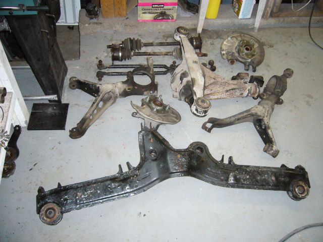
Time for some heavy lifting. My car came with an open diff, which was fine at stock power levels but at around 500HP it makes for some rather interesting driving. In fact, I'd qualify it as downright dangerous. Aside from that, there is the issue of wasting most of the power the engine is putting out in loss of traction. It is time to go to an LSD, so I sent off a spare S4 GXL LSD out to the transmission shop for a rebuild and set about pulling down the entire rear subframe. While not a particularly hard job, it is one that requires two people and multiple jacks. I also started pre-soaking most fasteners with PB Blaster a few days before and thoroughly cleaned up all the threads before attempting removal. With the subframe assembly out of the car, it was tossed up on the bench for further disassembly.
Pulling the subframe leaves a gaping hole in the rear of the car. I'll be replacing those parking brake cables since they are easy to access.
![]()
Aside from the ridiculous DTSS bushing bolts, it didn't take much effort to disassemble the rear subframe. The control arms and subframe were sent out for sand blasting, and the hub assemblies were sent to the machine shop to have the bearings replaced. The old bearings were well past worn, with almost 300K of hard driving. I won't miss the interesting noises they made while in motion. During removal, the DTSS bushings got fairly torn up so I ordered some Delrin DTSS eliminators from Mariah.
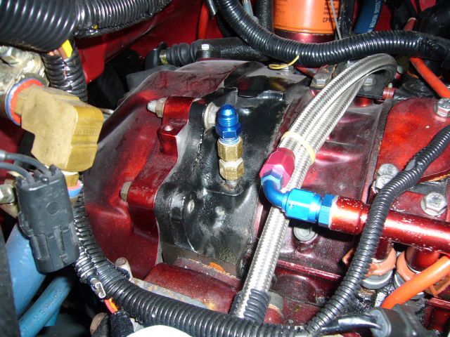
I mentioned earlier that I wanted to eliminate the crappy Push Lock hose feeding the turbo with coolant. While the water pump housing was straightforward to tap, the nipple in the rear iron was a little bit of a pickle. I could attempt to drill and tap it, but what if the thin and brittle casting cracked? That would not be good. Indeed, a friend had just managed to crack an FD rear iron trying the exact same maneuver.
The only real option was to install a compression fitting on the stock nipple, so I did a test using a spare S4 NA block that was lying around. It was already a water pumper so it's not like I could ruin it more. With a cutting wheel on the Dremel, I cut the flare off of the nipple and then smoothed it out with some emery cloth. A 3/8" compression fitting with a 1/4" NPT thread was carefully test fitted. This seemed to work out quite well. The ferrule sealed against the stock barb without any real drama. It was then time to try it for real, in the car, on my engine.
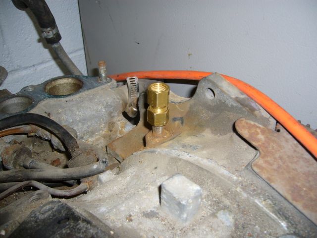
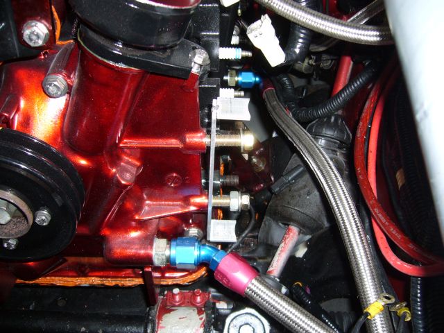
This was nerve-wracking to do, but it seems to have worked. Plenty of pipe dope was used both as lubrication and a sealant, and I spent a good amount of time with the sandpaper making sure that the nipple was smooth and fit well inside the ferrule. The AN fitting is a 1/4" NPT to -4 adapter. These compression fittings handle thousands of PSI, so I doubt there is much chance of a leak here.
If you decide to do this, I would highly recommend thinking about it before the engine is built and simply tap the iron using a standard straight thread, not a tapered pipe thread. A straight thread would be far less prone to cracking the iron. Then just seal it up with a crush washer and pipe dope.