| Home > RX-7 > My RX-7 > Project Tina > Project Tina, August 4, 2004: Assembling The Engine, Modifying Lower Intake Manifold |
| Home > RX-7 > My RX-7 > Project Tina > Project Tina, August 4, 2004: Assembling The Engine, Modifying Lower Intake Manifold |
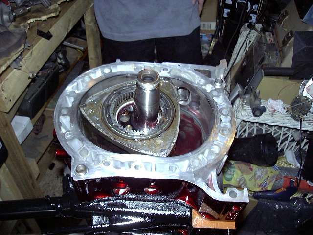
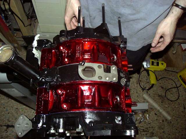
Next the intermediate was lowered in place. This is a two person job, as one person must push the eccentric up about an inch while the other rocks the housing over the lobe and onto the dowels. Thanks to Jeff for being there and providing the extra set of hands when necessary, as well as taking most of the pictures. It also helps to put the o-rings on both sides of the intermediate first. Don't forget the dowel o-rings!
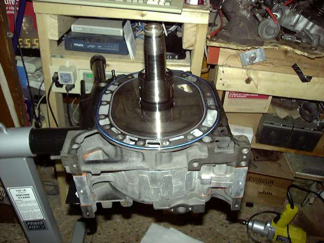
Second shot of the intermediate, this time from the port side.
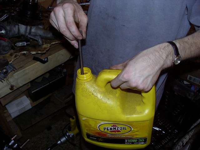
It's time to install the rear rotor, so the intermediate and eccentric was lubed up in preparation. It's kind of creepy how much the stuff looks like blood...(finally, I could have used the vampyre smiley, but it's no longer here...)
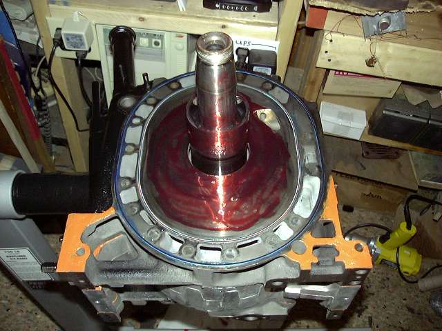
The rear rotor is placed. This picture also shows an absolute necessity in an engine build: Dr. Pepper.
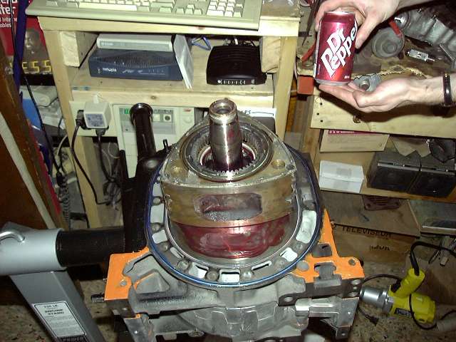
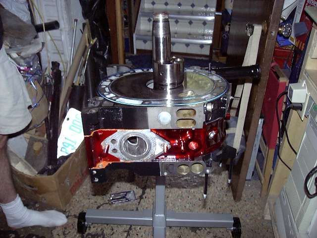
Initially, I forgot to super glue the apex seal corners in place before this housing was installed. This prevented the installation of the springs (the big one would catch on the gap created by the corner piece). So we needed to pull the housing, glue the seals, and then put the housing back. The springs then slid easily into place. This is not normally a problem as in a non-bridged engine the corner piece would face the rear of the engine.
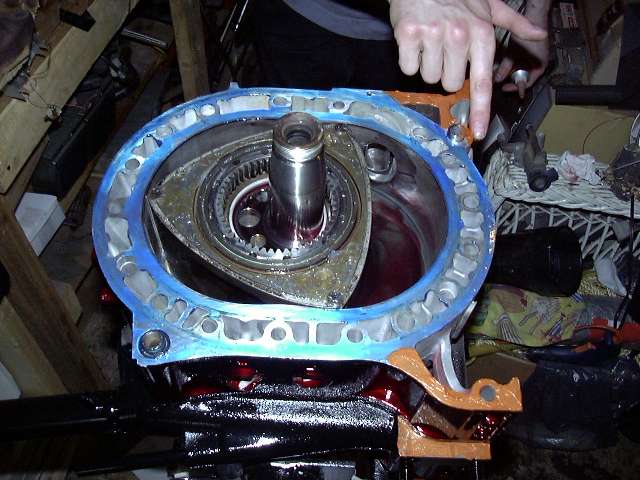
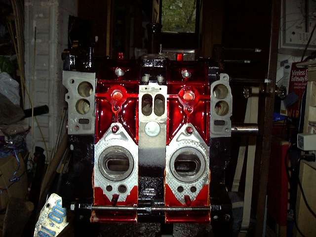
Sealants being spread on the rear housing. You can see the blue hylomar on the o-ring surface, and the copper silicone on the legs. Messy job.
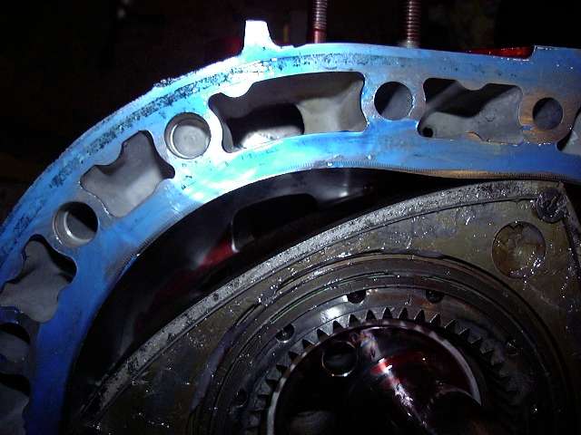
Just a closeup of the rotor's eye view of the housing, ports, etc.
And the rear plate was lowered into place. Don't forget the o-rings on the dowels!
Another view of the rear plate.
I then install the rear stationary gear. Of course, the bearing and shaft are lubed. There is also an o-ring that fits around the outside of the gear, and a VERY thin layer of sealant is put on the flange.
Time for the tension bolts. It's a satisfying feeling to ram each one of those suckers into place.
A small amount of oil on the threads assures even torque.
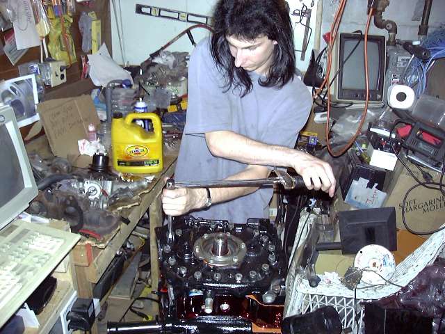
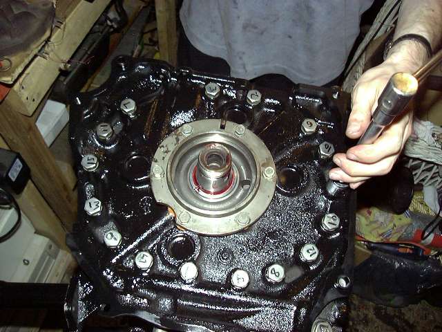
Now the pain: torquing them. It's done in three steps, to either 34 or 28 LB (I forget now). And it must be done in the order as shown by the numbers on the heads.
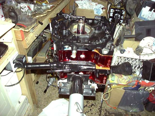
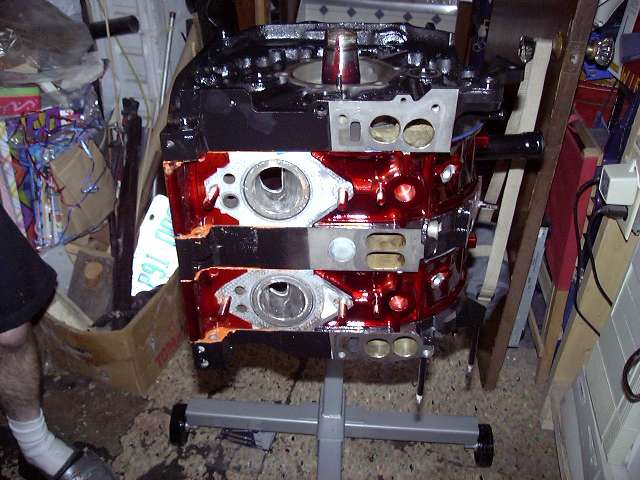
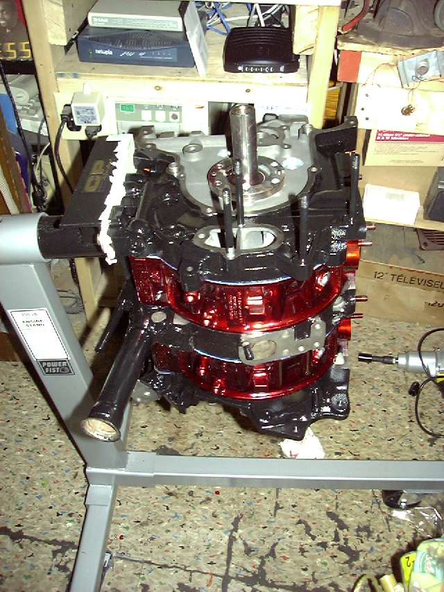
And here we have some views of the finished short block. The excess sealant is easily peeled off once it has completely cured. The next step is to set the eccentric end play, install the thrust plate, install the oil pump, front cover and hub.
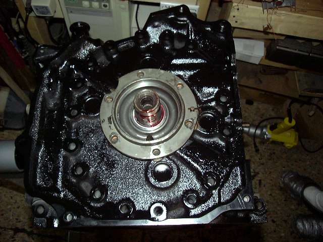
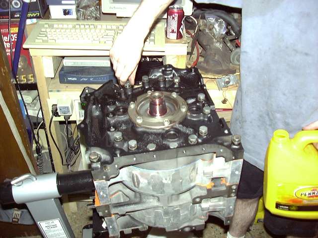
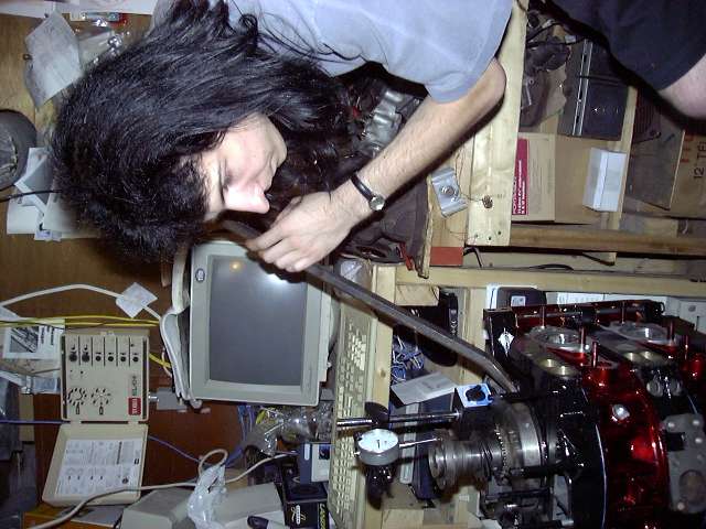
Checking the eccentric shaft end play is VERY important. This measurement is how much the eccentric shaft is allowed to move front to back. This happens, for example, everytime the clutch is pressed or released. The movement is set by 2 bearings and a spacer. To set the end play, the front assembly is put together without the front cover. A dial indicator is then used to measure the play of the front hub while the counterweight is pried up firmly with a bar. I believe that the factory spec is 0015" to .0028". I ended up with about 0.040" on the first attempt, which was the result of worn bearings. So I ended up just buying new bearings and a V spacer (there are about 8 lettered spacers with different thicknesses with which you use to set your play). After installing and rechecking, I came out with about 0.0020", which was right where I wanted it to be. For the record, most factory engines have a V spacer, so if you need to replace bearings, you might as well order the V spacer as well.
Now that the end play was set, it's time to actually assemble the front half. Here you see the front counterweight and oil pump. Of course, the proper spacer, bearings and thrust plate were installed under the counterweight, and the stationary bolts torqued to about 17 ft-LBS. Both the pump and bearings were thoroughly pre-lubed. The pump bolts get torqued to about 7 ft-lbs, and red Loctite is very important to keep the bolts from backing out.

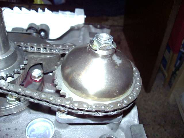
After that, the oil pump chain and sprockets were installed. This is a little challenging because everything has to line up. Someone needs to make an oil pump gearset, instead of a chain that will stretch.
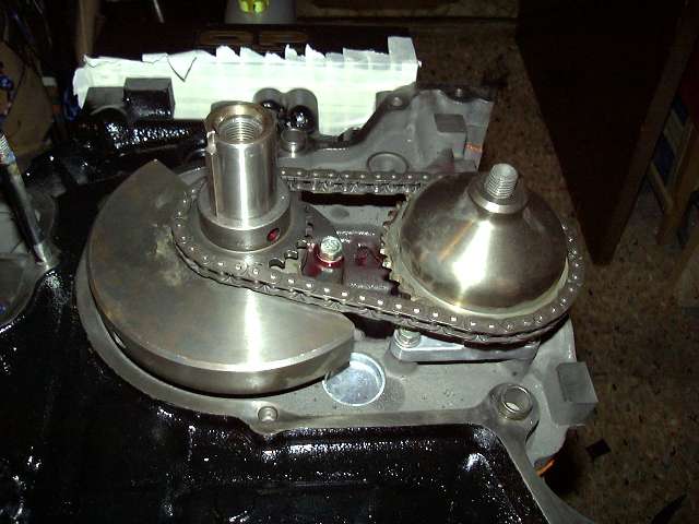
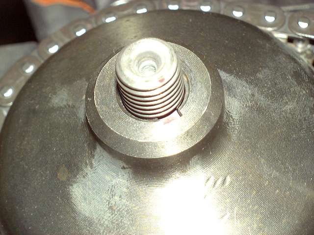
A closeup of the pump sprocket key. This is VERY important. Many engines have been lost because this key has slipped out during assembly. The result is that the sprocket begins to rotate on the shaft, the engine looses oil pressure, and then seizes. It's best to super glue it in place, but mine was already thoroughly stuck, so I didn't need to.
The pump shaft bolt gets torqued, and then the lock washer is bent up around the nut. That nut isn't going anywhere.