
| Home > My Projects > Tesla Coil |
For my grade 12 communications project, I chose to explain, build and demonstrate a Tesla Coil. This Web page is part of that project. It contains almost every aspect of the project, including a video of the actual coil demonstration.
The project contains a proposal, several optional activities that go along with the main project, a presentation and this Web page. Below is the first part of the project; the proposal.
Proposal For Tesla Coil Project After brainstorming, I have decided that my major project is to be a Tesla Coil.
What A Tesla Coil Is
A Tesla Coil (often shortened to "TC") is a high frequency, resonant step up transformer. The coil is driven by a lower-high voltage and a spark gap resonator. Since the coil is so perfectly tuned, a fairly small turns ratio (around 1:100) can cause a large increase in voltage. The coil I plan to build will be able to produce about 250KV (250,000V) at a frequency of about 500KHz. At this frequency, the voltage is almost completely safe, and much fun to play around with.
The Project
The project involves a fairly large amount of work in electronics and mechanical construction. There are a few problems associated with this activity though. First, there is always a danger when high voltage is involved. Although the coils output poses no real problem, it is the primary circuit (sometimes called the "tank circuit") that carries dangerous (but much lower) voltages that come right from mains. The problem is easily solved by just enclosing that circuit. The other problem is one of materials. The coil uses some rather exotic (read: expensive) parts. One of those is the wire. The secondary requires about 800' if 28 AWG wire to be wound onto a round form. This amount is about $45 on the roll. This is not that big of a thing when compared with the transformer. To drive the high voltage section, a lower, but still considered high voltage neon sign transformer is used. There seems to be an odd shortage of used neon sign transformers in London, and new ones go for about $150. I don't even want to go into how hard it will be to find a 0.005uF 10KV capacitor. These part related problems are easy enough to solve. Information Unlimited offers a TC kit for a very good price, which is what I am going to use. The only other real problem is the high frequency high voltage disrupting computers and such. Because of this, I will be unable to use my digital camera to take pictures of the coils operation because it simply won't work. These problems should are easy to solve by just not operating the coil around computers, and using an old fashioned camera and then scanning the pictures afterwards.
Support Activities
There could be many support activities for this project. Below is a small sampling:
- History On Tesla
- Solid State Tesla Coil Demonstrations
- Building Of An Output Terminal Or Triode To Increase Output
- Tesla Coil Video (With RealVideo Or Vivo)
- Pictures (Digital, Of Course)
- Effects Of High Voltage
- Study On Much Larger Coils
Four Optionals
- 1. Solid State Tesla Coils:
- Solid State TCs are almost the same as a traditional TC, except that instead of a spark gap oscillator, they use transistors or MOSFETS. This allows them to run on much less power and be built much smaller then a regular TC.
This activity will involve an explanation and demonstration of how a solid state TC works (I already have one built).
- 2. Building Output Terminal Or Triode:
- An output terminal/triode allows a regular Tesla Coil to output a much higher voltage by accumulating electrons. It also provides a uniform and smooth surface from with to draw arcs.
The terminal/triode will most likely be made from metal automotive tubing (in the case of a triode) or Styrofoam ball coated with tinfoil (in the case of a regular terminal). It then gets mounted on the top of the secondary.
- 3. Video:
- Of course, the video will have to be made after the actual coil. It will include video footage of the assembly, tuning and operation of the coil. There will also be some video showing really neat arcs and the affects of high voltage on people (glowing eyes and such).
- 4. Tesla Coils In Use Today:
- This optional will look at the use of TCs or their modern equivalent in electronics and industry today. There will be a section on some of the more modern devices like TVs, monitors, etc.
After I wrote the proposal, I began building the coil. The whole construction took about two and a half weeks. The construction process is described below.
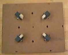 |
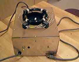
This is the first step in the construction. The mounting brackets for the primary are installed in the cover of the case. The primary brackets are made of plastic and secured with plastic ties. The primary winding slips through holes in the brackets. |
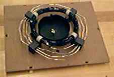 |
Next I would the primary windings. There are actually two parts to the primary; a non-insulated section and an insulated section. The insulated section makes up most of the winding. The non-insulated section is there for attaching the adjustible tap lead. The end cap to support the secondary was also installed at this point. Electrical connections for the two grounds needed in this part of the circuit were then made. |
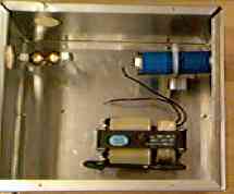 |
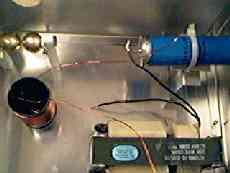
I then assembled the case and installed the capacitor, spark gap and transformer. Note that no electrical connections between these components have been made yet. |
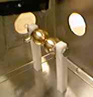 |
The spark gap observation windows were installed next. Notice the black tape holding it on. This was removed once the epoxy dried. On the back window, there is a small threaded hole into which a plastic screw in installed. This screw serves to adjust the distance between the spark gap electrodes. |
 |
After the observation window, I installed the RF choke. This protects the transformer secondary from nasty RF generated by the rest of the coil. Note that nothing has yet been wired. |
 |
I then wired the circuit and installed the switch, power cord, neon power on lamp and attached the top to the base. The top makes a ground connection to the base by a section of wire that is brought into contact with the base once the top is screwed down. |
 |
After that, all I did to complete the coil was to attach the secondary, output terminal and place the high voltage warning stickers. Note the doorknob used as a temporary output terminal. Once the coil was completed, I brought it home and tuned it. |
After building the actual coil, there were 4 optional activities that needed to be completed. The first of these optionals was a small writing on Solid State Tesla Coils. This activity is presented here.
Solid State Tesla Coils This activity will examine the area of Tesla Coils known as "Solid State Tesla Coils". These coils are used in many places in which high voltage is required, such as TVs, gas discharge LASERs, etc. This activity will also look at how they are similar/different to "traditional" Tesla Coils.
The first thing about Solid State Tesla Coils is that they are not truly Tesla Coils. In fact, Solid State Tesla Coil is sort of an oxymoron, as in order to be a true Tesla Coil, the machine needs a spark gap. This spark gap is obviously not solid state. That aside, there are a few similarities and differences that should be pointed out.
Solid State Tesla Coils are similar in the respect that they use the same basic principle of operation; a high frequency resonant transformer. Because the primary and secondary are so perfectly tuned, there is a huge increase in voltage. For example, my favourite Solid State Tesla Coil schematic, located at http://www.aaroncake.net/circuits/hvgen.htm can generate over 30,000 volts of high frequency AC from a very low 12VDC.
This is basically where the difference ends though. Perhaps the most major difference is in how the transformer is constructed and driven. As the name implies, Solid State Tesla Coils are not air core transformers. Instead, they are usually wound on a ferrite form, much like a regular transformer (execpt that regular transformers are usually wound on an iron core). This is how TV flyback transformers are made.
The other way they differ is how they are driven. Instead of a spark gap, Solid State Tesla Coils use transistors or MOSFETs. Below are a few examples of the different configurations used. Bear in mind that there are others. This is just a general simplification.
Notice the use of all solid state components. Compare that to the traditional spark gap coil below.
The traditional coil uses a capacitor/spark gap combination to get the high frequency necessary for operation. Also, notice that an air core transformer with an adjustable primary is employed. This is more or less a standard schematic. The coil I built (and many others) use a choke between the capacitor/spark gap and secondary of the transformer. This serves to protect the transformer from dangerous RF.
So as you can see, traditional Tesla Coils and Solid State Tesla Coils have a few similarities and many differences. These differences are so great that Solid State Tesla Coils are not really Tesla Coils, but merely high frequency transformers.
Learning Log
- Exercised knowledge of Tesla Coils and transformers. This knowledge will be used when I design and build my big Tesla Coil this summer
- Finally learned how to draw the symbol of a MOSFET properly
- Practiced writing skills
- Learned the various ways Solid State Tesla Coils are driven
After I completed the section on Solid State Tesla Coils, I chose to build an output terminal for the coil. This termainal replaces the temporary terminal (a doorknob) the coil was built with.
Output Terminal Proposal
An output terminal is a necessary part of a Tesla Coil. Coils built without an output terminal of some kind often have poor performance and just generally look bad. This being the case, my coil also requires an output terminal. The terminal I plan to build will replace the temporary door knob terminal that is on the coil now. It will either be a triode or just a regular round terminal.
Technical Report
The terminal I have decided on will be a regular round terminal. I chose this because the materials are much easier to get and much less expensive than those of the triodial terminal.
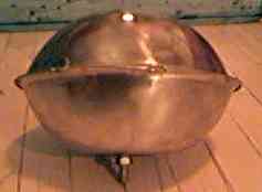
This terminal is made of two stainless steel salad bowls fastened together. Originally I planned to solder them, but that proved impossible due to the stainless steel used. That was not much of a problem because the school has a fair amount of welding equipment. I tried to weld it, but because the bowls did not form a perfect seal, that also didn't work. I finally ended up just taking it to a welding shop and having them do it. A bolt on the bottom attaches it to the top of the secondary coil. A picture of the finished terminal is below.
Learning Log
After the output terminal was completed, I was finally ready to give a good demonstration of the coil. The demonstration was filmed so that I could use that video for this activity.
Tesla Coil Demonstration Video
Proposal
This will be a video of the demonstration of the coil to the class. It will include all the neat stuff that can be done with the coil. The video will be recorded in analog form then captured to a computer and edited there. It will then be compressed for streaming over the Internet.
Technical Report
The video recorded without any problems, aside from some background noise from the wood shop class next door. The real problems began when I went to capture and edit the video. First off, I had to wait about two weeks for Adobe Premiere to come in. After that was settled, it took a whole period to install the thing. After installing it, I found that I had to use the ATI capture card's software to do the actual capture before the editing could begin. The video captured fine, but the audio did not. It took two periods to figure out that I needed to use the sound card to get the audio instead of the capture card. This is strange because that card has stereo audio inputs. After the video was captured, I needed to edit it. Adobe Premiere has got to have the worst interface I have ever seen. They completely ignored the standards when they programmed it. It took a week to figure out how to edit. After it was finally edited, there were a few problems saving the finished video, but those were easily cleared up by changing compression schemes.
I used The Vivo Active Producer to compress the video for transmission over the Net. This had a few problems, but those were solved by using a copy of the Producer from my hard drive instead of the one I downloaded at school. After 20 minutes of compressing, I FTPed the resulting 1.24 meg file to myself. The video is about 12 minutes long and can be viewed with the Vivo Active Video Player plugin.
Learning Log
- Practiced presentation skills
- Learned how to use Adobe Premiere (importing, editing, saving, compressing)
- Got practice in selecting the right compression format for the right job
The last optional I did was a little paper explaining the practical (and sometimes not-so-practicle) use of Tesla Coils today. This included the use of traditional spark gap type coils as well as solid state coils.
Tesla Coils In Use Today Even though the Tesla Coil is an old invention, there are still many uses for the devices today. This optional will take a look at some of those uses and try to peer into the future to uncover other potential uses.
The traditional coil has been delegated to mostly demonstration purposes these days, as what used to require large amounts of wire, power, a spark gap and other large components can new be done with smaller solid state components. Small coils like the one I built are usually found in schools, museums, magic shows, etc. Of course, they are an easy way to get a high voltage for home expirementing. Even though the high voltage can be gotten more effectively with solid state components, these components are usually way out of the budget of the average expriementer. Traditional coils can literally be lashed together with parts available at every hardware store. Movies also use small coils like mine as well as larger coils for special effects. Take a look at the time travel scenes in Terminator and Terminator 2 to see what I mean. The sparks you see are from a large Tesla Coil.
As for solid state coils, they are is very widespread use. Every TV, Computer monitor and most other things that use a cathode ray tube use what is generally referred to as a solid state Tesla Coil. Of course, from reading my optional on Solid State Tesla Coils, you know that they are not actually true Tesla Coils. Even so, they are referred to as such. So called Solid State Tesla Coils are easy to produce in small modules. Even though modern TVs and like equipment have shyed away from modules, these high voltage modules can still be found in older TVs. They are also a great expirementer's item. Solid State Tesla Coils are usually used when a high voltage is required for other devices because of their small size. The cousin of the Solid State Tesla Coil, the flyback transformer, is used in computer power supplies and other switching suplies. However, this is used to step down a higher voltage instead of increase a small voltage.
There will most likely be a surge in usage of at leat the solid state variety of Tesla Coils in the next 10 to 15 years. The reason for this would be the increased use of particle accelerators as we try to learn to use antimatter (a particle accellerator is a good way to make antimatter). One of the cooler uses would be in the so called ion motor. This is a motor that is powered by the force of ions expelled from some kind of orafice.This type of drive promisses to enable space craft to attain near light speed. As for other uses, they are only limited to the imagination. We will just have to wait and see what the future turns up.
Learning Log
- Learned some uses of solid state and traditional Tesla Coils
- Found out about ion motors and some other cool future engines
- Learned about special Tesla related effects in movies
- Practiced research and writing skills
And so ends this project. If you haven't already, you can View The Video of the demonstration. Note that you will need the Vivo Active Video Player in order to see the video.