Automatic 12V Lead Battery Charger
Printed from: Aaron's Homepage Forum
Topic URL: http://www.aaroncake.net/forum/topic.asp?TOPIC_ID=5954
Printed on: Apr 05 2026
Topic:
Topic author: drilon
Subject: Automatic 12V Lead Battery Charger
Posted on: Mar 11 2007 12:00:48 AM
Message:
Moderator pls help me. How does this circuit work, especially the function of the SCR and TRIAC? please help me. Your Answer will be very much aprreciated.
Replies:
Reply author: Aaron Cake
Replied on: Mar 11 2007 11:53:13 AM
Message:
I've described in detail how this circuit works before. Try a search for "how battery charger works", "battery charger explanation", etc.
Also, moving to Power Supply.
Reply author: drilon
Replied on: Mar 12 2007 07:57:00 AM
Message:
I tried to search that but i cant find the answer to my questions... thanks anyway....
this is the schematic of the charger im talking about...
can anyone tell me how R2, Q1(TRIAC) and Q2(SCR) works?
Q2 drives the LED to turn on right? how?
please help me ^_^
Reply author: Aaron Cake
Replied on: Mar 12 2007 10:13:29 AM
Message:
OK, I'll do it again since I can't seem to find the explanation either. This will be quick and dirty...
T1 steps down the mains to a little over 12V, D1 rectifies this to a pulsing DC. R1, R2 and R3 form a voltage divider between the + and - of the battery. The output of this divider is set by R2. When the output voltage is not enough to make D3 conduct, Q2 is switched off. Thus, Q1 is switched on via current through R4 and R5. This allows Q1 to conduct into the battery and raise it's voltage. As the battery voltage increases past the point the output of R2 causes D3 to conduct, Q2 is switched on. This pulls current away from D2, pulling pulling current away from the gate of Q1. Q1 thus switches off and charging stops. At the same time, D4 illuminates as the voltage across it increases. C1 helps control oscillation that can occur, R9 makes sure that Q2 is always switched off until D3 starts to conduct.
Reply author: drilon
Replied on: Mar 13 2007 08:15:52 AM
Message:
OK thanks for the explanation, it helped me a lot ^_^
Reply author: drilon
Replied on: Mar 13 2007 08:40:29 AM
Message:
another question hehhe.... i have jsut constructed this circuit and the output voltage is only arounf 7-9V is it ok?
Reply author: Aaron Cake
Replied on: Mar 13 2007 09:38:47 AM
Message:
It should measure above 12V with no load. What is the ratings for the T1 that you used?
Reply author: drilon
Replied on: Mar 13 2007 9:04:40 PM
Message:
i only used 3amperes transformer T_T
Reply author: lester
Replied on: Mar 14 2007 03:39:13 AM
Message:
i also have a question here. is it possible for me to add another led indicating that the battery is currently charging and will turn off when the battery is fully charged? if yes wer can i place it? thank in advance
Reply author: drilon
Replied on: Mar 14 2007 08:19:37 AM
Message:
i only used 12v 3 amperes transformer
Reply author: Aaron Cake
Replied on: Mar 14 2007 10:42:33 AM
Message:
lester: A LED through a series resistor between teh gate of Q1 and ground will light when the battery is charging. You'll want to find a LED with a very low operating current to avoid switching off Q1.
drilon: What is the AC output voltage of the transformer. If it's at 12V or less, then you may be getting low output voltage due to the drop through D1 and Q1. What happens if you adjust R2 with the circuit connected to a battery?
Reply author: drilon
Replied on: Mar 14 2007 8:27:53 PM
Message:
the AC output is around 12.3V.
the LED light up when i adjusted the potentionmeter..... the battery with the voltage of 12.89V.
its like the potentiometer sets the maximum voltage the battery can be charged on...
the battery charge on a rate of around 0.01V per second...
Reply author: lester
Replied on: Mar 14 2007 9:54:20 PM
Message:
You mean it would be connected in parallel with the gate of Q1 and the ground? not in series with the gate and D2? will it turn off wen the charger stops from charging the battery? thank a lot. i really appreciate it..
Reply author: kivdenn
Replied on: Mar 15 2007 08:22:15 AM
Message:
Hey guys am wondering what will happen if I use a full wave rectifier between the circuitry and the transfomer Thanks in advance
Reply author: Aaron Cake
Replied on: Mar 15 2007 09:08:56 AM
Message:
drilon: So it's working?
lester: Connect one end of your series resistor to the cathode of D2 (the value of the resistor depends on your LED....If you want to guess, it's hard to go wrong with 1K though it may pull too much current away from Q1...up the value if this is an issue). The other end of the resistor goes to the anode of the LED, and the cathode of the LED goes to ground.
kivdenn: The circuit relies on the pulsing DC of a half wave rectifier to allow the SCR and TRIAC to shut off when the voltage falls to zero. With smooth DC, they would remain clamped on. A full wave UNFILTERED rectifier still should work fine.
Reply author: drilon
Replied on: Mar 15 2007 8:17:46 PM
Message:
yup it's working, im just wondering why the output is only around 7-9V
thanks again it helped me a lot =)
Reply author: lester
Replied on: Mar 15 2007 10:17:17 PM
Message:
thank you very much.... one last quesation, do you know wat output current it would generate? knowing it will give me an idea on how long it would charge batteries of diferrent type. thanks....
Reply author: Aaron Cake
Replied on: Mar 18 2007 10:55:18 AM
Message:
The maximum current is set by the rating of T1. How much current the battery will accept depends on the voltage you charge it at. This cicuit will generally supply 3-5A of current if you have a transformer capable.
Reply author: patogh
Replied on: Sep 26 2007 12:04:42 PM
Message:
Hi everybody, i have a question, how can i control the time of charge of a lead battery in these circuit???
Reply author: Aaron Cake
Replied on: Sep 29 2007 10:08:28 AM
Message:
The charge time depends on how long it takes the battery to reach it's fully charged voltage. It's entirely dependant on the batter itself.
Reply author: freelirodskater
Replied on: Oct 08 2007 03:41:50 AM
Message:
ei what if i cant find brx49 SCR for Q2? what else can i use to replace it...pls help me..tnx!
Reply author: patogh
Replied on: Oct 08 2007 10:09:27 AM
Message:
Thanks Aaron for the answer. I have a new question, i cant find R2 (100 ohm pot). I found a 1k ohm variable resistor, can you tell me how can i change the resistors with R2 value 1k ohm?. Thanks gg.
Pato
Reply author: patogh
Replied on: Oct 18 2007 6:12:50 PM
Message:
Hi guys, I have another question. How can i reduce more the oscillation effects?. In my cricuit i have a little oscillation when batery is becoming final charge. Thanx.
For information, I put in my circuit a full wave rectifier and it never charge the battery. Maybe its necesary to change some resistors values.
Reply author: Aaron Cake
Replied on: Oct 21 2007 10:18:14 AM
Message:
You can use fixed value resistors for R2 as it's purpose is to just set the final charge voltage of the circuit. The trick is you will need to try a bunch of values to get the proper finish voltage. Or get a 50 Ohm pot and put a 50 ohm resistor in series, or any combination of the above.
The oscillation is normal.
The full wave rectifier will not work as the SCR needs the voltage to fall to zero in order to turn it off.
Reply author: zouzanda
Replied on: Jan 11 2008 11:21:17 AM
Message:
hello i have a question and i need an answer as fast as posible plzzz. how can i limit the output charging voltage to a max voltage lets call it A and a min voltage for it to start to charge again called B and thanx in advance
Reply author: zouzanda
Replied on: Jan 11 2008 11:30:04 AM
Message:
one more thing if i wanna make it a 10 A charger should i just change the T1 or i need to change Q1 and Q2 too?
Reply author: Aaron Cake
Replied on: Jan 12 2008 10:43:07 AM
Message:
Looking at the circuit, you can see that nothing limits charge current except for T1, D1 and Q1.
Reply author: zouzanda
Replied on: Jan 12 2008 11:43:55 AM
Message:
what if i wanna linit the charge to a high voltsge snd a low voltage?? for example to stop charging at 13,8V and to start again at 11.8V plz if u can help me as soon as posible cz i really need to implement the circuit
Reply author: zouzanda
Replied on: Jan 17 2008 11:59:35 AM
Message:
ok i did the circuit i just need to know should i leave it to charge then the light will turn on and i can adjust it or what should i do cz until now the light is not turning on even though iv been chrging it for 30 min and the volt meter on the end reads 13.6v while the battery is conected plz if someone could help me i apretiate it :)
Reply author: zouzanda
Replied on: Jan 17 2008 1:57:43 PM
Message:
im geting 6v to 7v on the output mt T1 is 220-12 5A
is that normal cz i think with this voltage Q2 will never turn on right?
Reply author: Aaron Cake
Replied on: Jan 20 2008 10:55:19 AM
Message:
The circuit will automatically begin charging again if the battery voltage falls below the turn off point. This is why it is "automatic" and not "manual".
You need to adjust the finish voltage as per the instructions on the site site before the light will work properly. Have you followed these instructions?
Reply author: hanz360
Replied on: Jan 22 2008 09:27:51 AM
Message:
moderator pls help me w/ this., it possible to connect a diode at positive/negative side of the output to prevent the current from battery entering the circuit? if yes is there any effect to the circuit? thanks in advance
Reply author: zouzanda
Replied on: Jan 24 2008 11:18:19 AM
Message:
man ofcourse u can't cz this circuit needs to test the voltage on the battery so if u used a diode ull prevent that from happening so Q2 will never turn on
Reply author: Aaron Cake
Replied on: Jan 27 2008 10:35:30 AM
Message:
What he said. A diode at the output will prevent the circuit from seeing the voltage of the battery.
Reply author: pebe
Replied on: Jan 27 2008 10:55:33 AM
Message:
quote:
Originally posted by zouzanda
man ofcourse u can't cz this circuit needs to test the voltage on the battery so if u used a diode ull prevent that from happening so Q2 will never turn on
That's only partially true. With a diode fitted the circuit will see 0V battery volts so it will assume the battery is flat and switch on the charger. Once the circuit is charging and the diode is conducting then it will 'see' battery volts plus 0.7V.
All you need to do is set up the potentiometer to give a charger output 0.7V higher than without the diode.
Reply author: hanz360
Replied on: Feb 01 2008 10:14:01 AM
Message:
what i mean is a "blocking Diode",preventing the current entering the circuit when you unplug the charger and the battery still connected to the charger, so that the battery will not be drain...
Thanks for the info guys..
Reply author: hanz360
Replied on: Feb 02 2008 07:28:54 AM
Message:
another question.., i have a NiCd and NiMH batteries and it's require a 12V charger to charge it, so its possible that i can use this 12V Lead Battery Charger to charge my NiCd and NiMH batteries? thank's in advance
Reply author: audioguru
Replied on: Feb 02 2008 7:02:46 PM
Message:
Ni-Cad and Ni-MH batteries need a completely different charger circuit from the lead-acid battery charger.
Usually a regulated current is used and the small voltage peak-dip is sensed or the rapid rise in battery temperature is sensed to stop the charging when the battery is fully charged. ICs are made to charge these batteries.
Reply author: hanz360
Replied on: Feb 02 2008 10:52:10 PM
Message:
thank's audioguru for the info.
Any body knows the schematic diagram for 12v NiCd and Ni-MH batteries charger?
Reply author: audioguru
Replied on: Feb 02 2008 11:55:40 PM
Message:
A 12V Ni-Cad or Ni-MH battery is fully charged at 14.0V to 15.0V depending on the charging current.
Maxim-IC have some battery charger ICs and the schematic for the battery charger is in their datasheets.
The charger circuits are automatic to charge quickly but avoid the battery exploding if it is overcharged.
Reply author: carlmaggott
Replied on: Feb 11 2008 03:09:00 AM
Message:
What can I use as replacements for the BT136 and the BRX49??
Reply author: Aaron Cake
Replied on: Feb 18 2008 09:51:13 AM
Message:
Go to your favourite semiconductor manufacturers website and look it up in the substitution charts.
Reply author: vicky
Replied on: Mar 11 2008 07:04:02 AM
Message:
can i use the circuit on the http://www.aaroncake.net/circuits/charger2.asp to charge a 24v battery? If yes, what changes should i make.
Please help, its urgent
Reply author: kivdenn
Replied on: Apr 25 2008 09:49:21 AM
Message:
Why should resitors R4,R5,R7 and R8 be of high wattage yet they send current to the gate and the gate draws little current and also why are they four in number cant two of them of 2watts connected in series serve the purpose? Also these resistors are always very hot why is this? Thanks
Dennis
Reply author: Aaron Cake
Replied on: Apr 27 2008 10:54:24 AM
Message:
Ohm's law will show you how much power they must dissipate.
Reply author: kivdenn
Replied on: May 16 2008 08:52:21 AM
Message:
How can I modify this charger to charge a 24V battery bank? Thanks
Reply author: Brent
Replied on: May 19 2008 09:09:33 AM
Message:
Hi!I put car battery charger clamps on wrong posts.Have I blown up the charger as it smelled a bit,can it be fixed,and how has the battery been affected? thanks Brent
Reply author: wasssup1990
Replied on: May 19 2008 09:45:08 AM
Message:
-
The battery's fine. You'll have to desolder the blown parts in the charger and replace them with exact or equivelent parts.
-
Reply author: kivdenn
Replied on: May 20 2008 09:09:34 AM
Message:
quote:
Originally posted by kivdenn
How can I modify this charger to charge a 24V battery bank? Thanks
Guys why no body is replying me on this question please help cause I realy need to modify this circuit to a 24V battery charger. Thanks
Reply author: kivdenn
Replied on: May 27 2008 09:47:00 AM
Message:
Please do me favour and answer my queation. thanks
Dennis
Reply author: Aaron Cake
Replied on: Jun 02 2008 09:47:51 AM
Message:
Modifying the circuit for 24V is simply a matter of using the appropriate transformer and calculating the voltage divider to switch the SCR at the appropriate point (R1, R2, R3).
Reply author: kivdenn
Replied on: Jun 13 2008 09:36:27 AM
Message:
How about R4,R5,R7,R8? They seem to be making a voltage devider, dont there values change in the 24V Configuration? Thanks
Dennis
Reply author: Aaron Cake
Replied on: Jun 13 2008 11:27:33 AM
Message:
Don't worry about those...
The switch voltage is set by R1-3.
Reply author: adnansamra
Replied on: Jun 21 2008 03:02:07 AM
Message:
Dear all,
I think that this circuit is great, but it needs one thing to be totally magnificent, it is mentioned in teh notes that if main power was off the charged battery will slowly be discharged by teh circuit if the circuit was not shut off by the switch, can anyone make an adjustment to autmatically switch off the battery connection to the circuit in case no power is applied ? I think it is very important to reach this solution
Reply author: adnansamra
Replied on: Jun 21 2008 07:25:45 AM
Message:
I think I found the answer to this but i need to make sure if I put a diod right in the + pole of the battery i think it will work, but one thing to make sure of is will teh design made to use pulses affect the charging process,I need help here any one?
Reply author: pebe
Replied on: Jun 21 2008 08:39:19 AM
Message:
Look at page 3 of this thread. Using a diode was discussed there.
Reply author: adnansamra
Replied on: Jun 22 2008 02:29:04 AM
Message:
Sorry,
I have not been to all the pages, so I assume that means it will work , ok but where to put it on the positive bath of the battery or negative bath?, will a certain bath stop the circuit from working ? while the other bath is OK ?
another thing I am planning to use this to make an uninturrupted power supply what I am planning to do is the following I am going to utilize the battery electricity to use 741 to work as a not gate and after it a switching transistor to switch on battery power once a main power on input is off what do you think will it work?
thanks for the help in advance
Reply author: pebe
Replied on: Jun 22 2008 07:09:16 AM
Message:
The diode can go in either the positive or the negative battery lead. What do you mean by 'a certain bath'?
I cannot see how you would use a 741 opamp as a NOT gate. Could you explain in more detail?
Reply author: Aaron Cake
Replied on: Jun 22 2008 10:33:33 AM
Message:
You can't put a diode in any of the leads. Doing so will prevent the charger from seeing the voltage of the battery.
Also, please keep discussions of the op-amp based battery charger out of this topic.
Reply author: adnansamra
Replied on: Jun 22 2008 12:20:13 PM
Message:
So Aaron you are not with pebe about what he said in page 3 that when a diod is used the electricty sensing will sense flat volatage so it will recharge and then it can see the voltage limit?
about the OP , I am not going to use it to charge the battery it will only sense the main power to know if it is applied or not if it is it won't give the Switching transistor teh signal to open the battery's circuit to the load and visa vers what do you think?
Reply author: pebe
Replied on: Jun 22 2008 7:23:00 PM
Message:
quote:Read my posting - and think about it. If you feel there is something that will prevent it working, then please explain.
Originally posted by Aaron Cake
You can't put a diode in any of the leads. Doing so will prevent the charger from seeing the voltage of the battery.
Reply author: adnansamra
Replied on: Jun 24 2008 02:16:06 AM
Message:
Ok,
so is there another way to prevent the electricty being drawn from the battery? could you please help me on this
Reply author: pebe
Replied on: Jun 24 2008 02:22:14 AM
Message:
You could have a relay energised by the mains supply, and its NO contacts would connect the battery to the charger. Not as simple as a diode though!
Reply author: kivdenn
Replied on: Jun 24 2008 06:44:46 AM
Message:
When I switch off switch S1 sometimes the LED remains on, is this normal or it means that my battery is being drained? Thanks
Dennis
Reply author: kivdenn
Replied on: Jun 24 2008 08:18:49 AM
Message:
quote:
Originally posted by adnansamra
So Aaron you are not with pebe about what he said in page 3 that when a diod is used the electricty sensing will sense flat volatage so it will recharge and then it can see the voltage limit?
about the OP , I am not going to use it to charge the battery it will only sense the main power to know if it is applied or not if it is it won't give the Switching transistor teh signal to open the battery's circuit to the load and visa vers what do you think?
Why cant you use a mains powered relay switch that only changes states when the mains are on or off and this way it can togle between mains and the inverter part of UPS I have such a circuit infom me if you would like and I will give it you. Thanks
Dennis
Reply author: kivdenn
Replied on: Jun 24 2008 08:32:33 AM
Message:
quote:
Originally posted by pebe
You could have a relay energised by the mains supply, and its NO contacts would connect the battery to the charger. Not as simple as a diode though!
That is not practical especialy for me who is using this charger for commercial purposes where it is made to produce over 500Amperes to charge over 50 batteries at ago. Such a realy switch does not exist unless we use a number of mosfets. Does any body know how to go about it?Please help us. Thanks
Reply author: kivdenn
Replied on: Jun 24 2008 09:28:40 AM
Message:
Is there a way we can varry the output current with a potentialmetre or something because am using this charger to charge varous batteries of different sizes so small batteries will need small currents and vise vasa. How can I go about it? Thanks
Dennis
Reply author: pebe
Replied on: Jun 24 2008 3:33:21 PM
Message:
quote:How do you get that charger to produce 500A?
Originally posted by kivdennquote:
Originally posted by pebe
You could have a relay energised by the mains supply, and its NO contacts would connect the battery to the charger. Not as simple as a diode though!
That is not practical especialy for me who is using this charger for commercial purposes where it is made to produce over 500Amperes to charge over 50 batteries at ago......
Reply author: kivdenn
Replied on: Jun 25 2008 07:45:08 AM
Message:
I paraleled 32 BT136 Triacs of 16 Amps each for Q1 and one BT159 for Q2 and 3000watt 230V/18V transformer and 12 1N196A diodes of 45 Amps each and I used the same control circuit. The circuit is working perfectly well and I have used it for 9 months now. The only draw back is that you need plenty of heat sinking using cooling fans and huge heat sinks and also it has no way of varying current acording to the number of batteries being charged.Thanks
Dennis
Reply author: adnansamra
Replied on: Jun 25 2008 09:36:50 AM
Message:
Ok, I have thought of this solution for the drawn up issue,
if we sued a normal relay it will be hot especially if the electricty would stay disconnected for a long time , I have thought of two soltuions and tell me what do you think if it will work or not :
1- to use a relay but not a normal relay; to use a solid state relay, so will it indure hours of always on state ?
2- the second solution is to use a transformer with two seperate out coils one fot the circuit exactly as it is while the other goes to a bridge and then pulses a triac say BT136 in the way of the positive pole of the battery will it work, anyone who can offer help in this regard?
Reply author: adnansamra
Replied on: Jun 25 2008 09:41:03 AM
Message:
another question is it compulsary to have a fan? can't we just use a large heat sink of let us say 0.5c/w or a little less without a fan because as we know the triac will pass something like 4A*12V at maximum rate (correct me if wrong) so that means 48 watt at maximum rate?
Reply author: adnansamra
Replied on: Jun 25 2008 10:35:43 AM
Message:
please see (http://www.geocities.com/adnan_m_s/usingatriac.jpg)
for the my suggestion of using a triac
Reply author: adnansamra
Replied on: Jun 30 2008 03:53:12 AM
Message:
do you think this could work?
Reply author: kivdenn
Replied on: Jun 30 2008 06:12:37 AM
Message:
You didnt show where the gate of the extra triac is connected. I is hanging in the air.
Reply author: adnansamra
Replied on: Jul 01 2008 09:39:36 AM
Message:
Terribly Sorry about that well it is coming from a bridge out put (+ pulse)
Do you think it well work or it will need a SCR to on the gate of the triac?
Reply author: adnansamra
Replied on: Jul 01 2008 09:52:31 AM
Message:
I need to ask about another thing Mr. Kivdenn,please
How much slowly will the battery be drain I mean How many milliamperes does it consume when main power is dead this is a very important Question for me?
Reply author: kivdenn
Replied on: Jul 31 2008 05:24:47 AM
Message:
quote:
Originally posted by Aaron Cake
Modifying the circuit for 24V is simply a matter of using the appropriate transformer and calculating the voltage divider to switch the SCR at the appropriate point (R1, R2, R3).
How do I do these calculations? Please help me. Dennis
Reply author: kivdenn
Replied on: Jul 31 2008 11:14:09 AM
Message:
Actualy looking at this circuit I think the battery will only discharge through resistrors R1, R2,and R3 becuase even when the triac alows power to flow back, it wont go beyond diode D1. That leaves the voltage devider alone connected to the battery for the purpose of sensing the the voltage levels. I strongly believe the dischrge current is very low and negligable. Thanks Dennis
Reply author: Aaron Cake
Replied on: Aug 01 2008 09:24:28 AM
Message:
Ohms law and the formula for a voltage divider.
Reply author: kivdenn
Replied on: Aug 01 2008 09:51:26 AM
Message:
I have no idea on Ohms law could you please help me a little. Thanks
Reply author: audioguru
Replied on: Aug 01 2008 10:42:10 AM
Message:
Ohm's Law has the most basic rules for electrical circuits.
The rules define voltage, current, resistance and power.
Look in Google for many links that explain Ohm's Law.
Reply author: JUAN DELA CRUZ
Replied on: Aug 03 2008 04:05:56 AM
Message:
quote:
Originally posted by Aaron Cake
Ohms law and the formula for a voltage divider.
Hello Mr. Administrator...
Can your Battery charger (automatic) can be modify to charge huge batteries (approx. 150AH- 200AH).
Thank you
Reply author: kivdenn
Replied on: Aug 05 2008 02:46:33 AM
Message:
Yes it can cause I modified it to give out up to 100Amps by paralleling 7 BT139 Triacs and they work fine. Dennis
Reply author: kivdenn
Replied on: Aug 05 2008 02:48:03 AM
Message:
quote:
Originally posted by audioguru
Ohm's Law has the most basic rules for electrical circuits.
The rules define voltage, current, resistance and power.
Look in Google for many links that explain Ohm's Law.
Please some body help me do the Ohms law math if the moderator cant. Thanks
Reply author: pebe
Replied on: Aug 05 2008 04:21:00 AM
Message:
Knowing Ohm's Law and being able to apply it is a basic essential to working in electronics.
You really should make an effort to understand it - it's not difficult. You cannot expect to go through life being spoon-fed.
Reply author: kivdenn
Replied on: Aug 06 2008 06:00:46 AM
Message:
Ok but will ask for help if I get stuck and you help me? Thanks
Reply author: pebe
Replied on: Aug 06 2008 08:31:09 AM
Message:
quote:Yes, of course.
Originally posted by kivdenn
Ok but will ask for help if I get stuck and you help me? Thanks
Reply author: kivdenn
Replied on: Aug 12 2008 11:49:41 AM
Message:
I have made some sreaserch and I have discovered that Current= Volatge/Resitence and that this formular can be manipulated to get any un known. But I have failed to apply this formular to this charger circiut so that I can get values to R1,R2,R3 for 24V battery bank.
Also how does this charger discharge the battery when disconnected from the mains?
Reply author: 8888
Replied on: Aug 25 2008 12:54:55 AM
Message:
what can i use for Q1 and Q2
Reply author: 8888
Replied on: Aug 25 2008 12:56:23 AM
Message:
where did you get you parts
Reply author: Aaron Cake
Replied on: Aug 30 2008 10:45:49 AM
Message:
Try the local electronics store. Failing that, DigiKey.
Reply author: pruisgroup
Replied on: Sep 06 2008 11:01:41 AM
Message:
quote:
Originally posted by kivdennquote:
Originally posted by Aaron Cake
Modifying the circuit for 24V is simply a matter of using the appropriate transformer and calculating the voltage divider to switch the SCR at the appropriate point (R1, R2, R3).
How do I do these calculations? Please help me. Dennis
Reply author: pruisgroup
Replied on: Sep 06 2008 11:05:40 AM
Message:
maybe the following site can help you with calculations, www.electronics2000.co.uk. Download the electronics assistant, the program have calculators for various electronic problems etc. I found it to be very handy.
Reply author: pebe
Replied on: Sep 06 2008 3:54:44 PM
Message:
Change R1 to 1K.
Reply author: eko_sph_1986
Replied on: Sep 28 2008 01:50:24 AM
Message:
Hi, thanks to share your knowladge about charging to me.
I have a question.
How much are current flow to battery? (T1 is 12 v 5 A) Is okay if i use for 12 V 5 A lead acid?
Thank you.
Reply author: Aaron Cake
Replied on: Sep 28 2008 11:21:25 AM
Message:
Yes.
Reply author: eko_sph_1986
Replied on: Oct 03 2008 11:29:41 AM
Message:
Hi, I can't try to make your charger circuit, but it doesn't work.
I use the same components at all. and using T1 = 12V 5A.
When I check the voltage output is zero (0) volt, and no current.
I check to the T1 the output is around more than 12v (AC).
At triac I check on gate and MT1 have around 12 v, but the gate has the lower than MT1.
Any sugestion what should i do?
Thanks
Reply author: eko_sph_1986
Replied on: Oct 14 2008 02:22:09 AM
Message:
Hey I know why my circuit did not work. It because my false. I think TRIAC have same thing at MT1 and MT2 pin but it different. Now your charger circuit is working. Thanks a lot to share.
By the way I have some question.
1. How can I know that the circuit is charging the lead acid?
2. What method in this circuit? (Constant Voltage or Constant Current or something else)
Reply author: Aaron Cake
Replied on: Oct 20 2008 09:43:42 AM
Message:
1. Measure the voltage of the battery while it's on charge. It should gradually rise.
2. The circuit is neither constant voltage nor constant current. It's close to constant voltage but the current pulled will depend on the battery voltage.
Reply author: Electrician
Replied on: Nov 12 2008 11:14:29 AM
Message:
I was wanting to know if I would be able to use a 5.1 volt zener in place of the 5.6. It just happends to he what I have in my shack right now.
Reply author: pebe
Replied on: Nov 12 2008 2:18:41 PM
Message:
With a 5.1K zener the slider of the pot will have to be set at 5.7V instead of 6.2V for the 5.6V zener.
The circuit will work OK if you change R3 from 330ohms to 270ohms.
Reply author: Electrician
Replied on: Nov 12 2008 7:35:34 PM
Message:
Thanks for the help. I am now only having one problem with the circuit. I change out r3 for a 270 ohm and the zener to 5.1v. Now I am unable to adjust r2 to get a charge voltage of 13.8 to the battery I am only getting a max of 13.08 volts. Other Wise the circuit is working fine. Is there another adjustment I need to make that I am not seeing.
Reply author: kivdenn
Replied on: Jul 31 2009 03:57:01 AM
Message:
Can I use this circuit to control the charging of my battry by a solar panel? Thanks
Reply author: Aaron Cake
Replied on: Aug 10 2009 09:37:56 AM
Message:
The circuit requires a pulsing DC so you can't use it directly from a DC source like a solar panel. The voltage from a panel also varies wildly so you would need some kind of DC-DC converter to bring the voltage up or down to match the battery.
Reply author: kivdenn
Replied on: Aug 10 2009 11:11:15 AM
Message:
No brother the voltage a solar panel is very stable it is the current that isnt stable. Nevwer the less how can I change a smooth DC voltage to pulsing DC voltage? Thanks
Dennis
Reply author: kivdenn
Replied on: Aug 10 2009 11:11:55 AM
Message:
No brother the voltage a solar panel is very stable it is the current that isnt stable. Nevwer the less how can I change a smooth DC voltage to pulsing DC voltage? Thanks
Dennis
Reply author: oslinux23
Replied on: Aug 24 2009 10:17:26 AM
Message:
can you send me the pcb please. thank you
oslinux23@yahoo.gr
oswindows23@gmail.gr
Reply author: kivdenn
Replied on: Feb 27 2010 04:40:25 AM
Message:
What happens if I use a mosfet for Q1 because I have failed to get a triac in a TO-247AC package and I wanted to use IRF64N instead. Thanks
Reply author: Aaron Cake
Replied on: Feb 28 2010 10:08:40 AM
Message:
Other changes will be necessary to use a MOSFET. They have totally different characteristics then TRIACs. Can you not find a suitable substitute for this TRIAC? The exact characteristics aren't critical, as long as the gate current and voltages are the same.
Reply author: kivdenn
Replied on: Mar 01 2010 11:18:16 AM
Message:
My problem is that these small BT139 cant stand the heat and they necessitate to use a very big and bulky heat sink which is not good. I used RFP150N as D1 by connecting together its gate and source terminals and it stands that heat because they are both on the same heat sink. So I would like to use the same mosfet for Q1 because it has the ability to stand the heat. Please help me redraw the circuit to show the extra parts that would enable to use a mosfet in place of Q1. Thanks
Dennis
Reply author: kivdenn
Replied on: Mar 04 2010 10:18:51 AM
Message:
Aaron cake please help me with this. Thanks
Dennis
Reply author: yakitech
Replied on: Mar 17 2010 05:15:18 AM
Message:
hi aaron,pls could you help me a 12v charger circuit for my dcmotor powered generator.the charger will pick its ac from the gen ac output when gen is on and at the same time charging the battery without affecting the ac output of the gen.my battery is a 40a/h lead acid batt.you can reply via my e-mail [yakitech@yahoo.com]URGENT PLS.thanks
Reply author: pebe
Replied on: Mar 17 2010 06:35:50 AM
Message:
You cannot use a battery to power a generator, and then use the generator's output to charge it.
Reply author: Aaron Cake
Replied on: Mar 20 2010 10:14:44 AM
Message:
Why are you getting so much heat from the circuit? What are you charging?
Reply author: pillow
Replied on: Mar 24 2010 12:14:18 AM
Message:
amended
Reply author: pebe
Replied on: Mar 24 2010 01:24:30 AM
Message:
Read Aaron's reply on 10 August for the answer.
Reply author: Electromaniac
Replied on: Jul 31 2010 5:20:36 PM
Message:
Hey,
My charger also has an output voltage (without load) of 8Volts.
Do you know whats wrong? When charging, the is no problem, but as you said before, without load it should be 12.
PS: I think the battery is now "broken", i tested previously and it had 11.9 volts, vou it has 8.5. All components are the ones on the page, no equivalent ones were used.
BTW thanks for all these circuits! Theyre very usefull.
Reply author: RRITESH KAKKAR
Replied on: Aug 20 2010 04:30:39 AM
Message:
I want to know how to check mosfet as it is depletion or enhanched type plz tell....?
Reply author: RRITESH KAKKAR
Replied on: Aug 20 2010 04:31:55 AM
Message:
as i am having IRF 3205....!
Reply author: peterpl
Replied on: Dec 05 2010 4:45:53 PM
Message:
Could you tell me what happens if T1 secondary voltage will be 18 V AC ? What will be the battery charging voltage ? Should I change the resistors ?
Reply author: Aaron Cake
Replied on: Dec 05 2010 5:05:07 PM
Message:
If T1 is a transformer rated at 12V, then the output voltage will be higher when it is not under load. 18V is probably reasonable.
Reply author: kivdenn
Replied on: Dec 23 2010 2:37:53 PM
Message:
Am going to make a 24Volts version of this charger but am simply going to double the values of the components because I dont know how to find the appropriate values. If any body can help me before I begin, I highly appreciate. Thanks Dennis
Reply author: kivdenn
Replied on: Dec 25 2010 07:14:05 AM
Message:
I have made the circuit and it works fine but R4 to R8 get very hot in a short time. I used 162 ohms 2watts.Also resistor 2 seem not to be of the right value because the LED just blinks when adjusting for a higher voltage instead of completely turning off. Please help me find the right component values for these resistors. Thanks
Dennis
Reply author: audioguru
Replied on: Dec 25 2010 10:49:04 AM
Message:
Don't you know that when you double the voltage across a resistor then its power (heating) is 4 times? If you double the voltage and double the value of the resistor then the power (heating) is double.
Reply author: kivdenn
Replied on: Dec 25 2010 12:28:52 PM
Message:
Thanks how about variable resistor?
Reply author: audioguru
Replied on: Dec 26 2010 09:39:41 AM
Message:
quote:
Originally posted by kivdenn
Thanks how about variable resistor?
Although a very expensive huge wire-wound variable resistor can be used, most variable resistors are for low power (less than 1/2W) and can control the conduction of some transistors that can get hot.
Simply use ohm's Law to calculate the correct resistor value.
Reply author: erki112
Replied on: Mar 14 2011 09:20:00 AM
Message:
I just made that circiut but the output voltage is around 9 v . when i connect it to charger ,it discharges the battery ,i tried to adjust pot but nothing happens ,the led always is light up. i use 2,5A 12V transformer which ac output is 13,1V. could someone help me wit that ,what would be the problem. Sorry for my bad english.
Reply author: erki112
Replied on: Mar 15 2011 6:20:01 PM
Message:
i found my problem the Q2 pins were changed . it charges the battery about 13,8 v .but how i test this circiut,because i dont know when the charging stops ,led dosent light up.i dont want to plow my battery . sorry for my bad english
Reply author: awt
Replied on: Mar 16 2011 06:35:06 AM
Message:
it is possible that the battery has not reached its 'high voltage cut off' already preset with R2. connect a voltage meter to the battery and adjust R2 when the battery reaches high voltage (say 13.8V or check the battery manufacturer's sheet) till the LED light up.
you can check here for another nice charger: http://www.simplecircuitsandprojects.com/circuits/lead-acid-battery-charger.html
Reply author: erki112
Replied on: Mar 16 2011 3:47:46 PM
Message:
i connected a fully charged battery to the charger but led didnt light up and voltage meter showed 15,6 ,battery started boiling, why didnt it turn of charging ,i tried to adjust pot but nothing happens. would the problem in zener diode. i metered voltage from between r2 and D3 ,there was about 5,6-7V wich changed when i turned pot . how much voltage there would be in the other side of D3.
Reply author: awt
Replied on: Mar 17 2011 04:40:14 AM
Message:
Let's do it together, just few info from u will help. What did u use as:
Q1 =
Q2 =
R4 =
R5 =
R7 =
R8 =
and d zener voltage of D3?
Reply author: erki112
Replied on: Mar 17 2011 10:31:15 AM
Message:
Q1 =bt136 triac http://www.oomipood.ee/?t=k_ki&i=1081316
Q2 =brx49 https://www.elfa.se/elfa3~ee_et/elfa/init.do?item=72-030-14&toc=0
R5,R7,R8,R4 =resistor 82R 2W http://www.oomipood.ee/?t=k_ki&i=2W%2082R D3 =Z-DI 5.6V 0.4W http://www.oomipood.ee/?t=k_ki&i=0.4W%205V6
i added links where i bought these.
Reply author: awt
Replied on: Mar 17 2011 1:47:57 PM
Message:
Good, open up R5 and R8. Then short circuit out R7 while replacing R4 with 680ohm and R6 with 560ohm. Adjust R2 at 'high voltage cut off'
Reply author: erki112
Replied on: Mar 17 2011 2:46:13 PM
Message:
im not good in enghlish,but do i have to remove R5 and R8.and bridge R7.and replace R4 with 680 ohm 2w resistor.and R6 with 560 ohm 1/4w resistor. and finaly set pot to the max and test
Reply author: awt
Replied on: Mar 17 2011 3:17:17 PM
Message:
Yeah! you are correct, but 2W is not needed for R4. 680ohm,0.5W is ok for R4.
Reply author: awt
Replied on: Mar 17 2011 3:58:16 PM
Message:
it doesn't matter, it will work. i only suggested that one with lesser wattage to reduce the cost.
Reply author: erki112
Replied on: Mar 18 2011 4:22:32 PM
Message:
i did what you said but nothing changes.expect the current went to 15V .i tried fully charged and empty batteries but charging dosent stop when battery is full. fully charged battery voltage was 12,8 V
I dont know what is wrong with it ,i have messed with this 2 weeks .
Biggest problem is that the charging dosent stop.I charged 1 empty battery wich was 11,8 v to 13V afther that battery started boiling.no charging switch off ???????
Reply author: erki112
Replied on: Mar 19 2011 4:48:06 PM
Message:
http://s822.photobucket.com/albums/zz147/nomad3334/?action=view¤t=PCB1.jpg here is pcb and how i connected components.
Reply author: erki112
Replied on: Mar 19 2011 4:52:29 PM
Message:
here are the links where i bought components
2X http://www.oomipood.ee/?t=k_ki&i=1%2F4W%20330R resistor 330ohm 1/4W
1X http://www.oomipood.ee/?t=k_ki&i=IPMGH%20100R pot 100ohm 1/4w
4X http://www.oomipood.ee/?t=k_ki&i=2W%2082R resistor 82ohm 2w
1X http://www.oomipood.ee/?t=k_ki&i=1%2F4W%20100R resistor 100ohm 1/4w
1X http://www.oomipood.ee/?t=k_ki&i=1%2F4W%201K resistor 1kohm 1/4w
1X http://www.oomipood.ee/?t=k_ki&i=220%2F25PHT capicator 220uF 25V
1X http://www.oomipood.ee/?t=k_ki&i=P600M-MBR p600 diode
1X http://www.oomipood.ee/?t=k_ki&i=1N4007-MBR 1N4007
1X http://www.oomipood.ee/?t=k_ki&i=0.4W%205V6 5.6V Zener Diode
1X http://www.oomipood.ee/?t=k_ki&i=LED5%20G-LC green led
1X http://www.oomipood.ee/?t=k_ki&i=1081316 BT136 TRIAC
1x https://www.elfa.se/elfa3~ee_et/elfa/init.do?item=72-030-14&toc=0 brx49
Reply author: royski007
Replied on: May 06 2011 2:28:47 PM
Message:
i was just wondering, i always thought the charger would have to be around 14V to charge a lead acid battery. but T is only 12V. how come?
Reply author: audioguru
Replied on: May 06 2011 5:52:36 PM
Message:
quote:
Originally posted by royski007
i was just wondering, i always thought the charger would have to be around 14V to charge a lead acid battery. but T is only 12V. how come?
The transformer is 12V RMS. its peak voltage is 17V which is reduced to 16V by the recifier. Its average voltage is a little less.
The circuit limits the charging current then the battery limits the voltage.
Reply author: rider21
Replied on: Aug 27 2011 02:40:12 AM
Message:
hi mr. administrator....can u please help me...what components i must change with the circuit if i only want to charge a 9volts battery...r.s.v.p.
Reply author: pebe
Replied on: Aug 27 2011 06:57:27 AM
Message:
quote:
Originally posted by rider21
hi mr. administrator....can u please help me...what components i must change with the circuit if i only want to charge a 9volts battery...r.s.v.p.
This is a lead acid battery charger.
There are no 9V lead acid batteries - they go in 2V increments.
Reply author: rider21
Replied on: Aug 27 2011 11:45:16 PM
Message:
ok...but i can i use a lithium battery instead?if i can...what components must i change sir?
Reply author: rider21
Replied on: Aug 27 2011 11:47:19 PM
Message:
is this circuit not applicable for a 9volts lithium battery?
Reply author: rider21
Replied on: Aug 28 2011 12:00:50 AM
Message:
mr pebe...kindly help me....thank you..
Reply author: pebe
Replied on: Aug 28 2011 03:36:01 AM
Message:
Like I said. It's for charging lead acid batteries.
Lithium batteries are a totally different breed and need to have a very sophisticated charger.
So,no. You cannot charge a lithium battery wih it.
Reply author: rider21
Replied on: Aug 29 2011 01:48:58 AM
Message:
ok..thanx........
Reply author: eddiegeer2001
Replied on: Nov 10 2011 9:39:18 PM
Message:
The led lights up when I first turn on the charger. When I connect the battery the led goes off.
The battery reads around 12.9 volts when I first turn on the charger and then increases to around 14.4 volts.
The voltage will then slowly drop. I turned off the charger when the battery read around 13.8 volts.
The led never comes on when the battery is connected.
What could be the problem?
Thanks for any help.
Eddie
Reply author: Aaron Cake
Replied on: Nov 12 2011 10:24:45 AM
Message:
Did you go through the procedure to calibrate R3?
Reply author: eddiegeer2001
Replied on: Nov 12 2011 11:35:38 AM
Message:
I set the pot to midway and then turned on the charger. The led lit up and then it went off when I connected a battery.
I measured the battery and when it read 13.8 volts I turned the pot. The led would not light up. I turned the pot both ways.
Eddie
Reply author: Zogpy
Replied on: Feb 11 2012 5:29:35 PM
Message:
Hi Aaron, I have a problem with this circuit, I only get 7-8 volts output. The Led is always on I need your help, I could not find the exact values for some parts like the Triac, I used BT137, 390 ohms resistors instead of the 330, 75k ohm 2w resistors instead of 82k, 221 ohm pot, MCR100-6 instead of the Brx49. I feel so disappointed, & I wish to get this charger to work. can you plz tell me what might be causing my problem.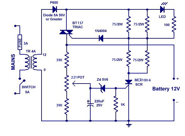
Reply author: Aaron Cake
Replied on: Feb 12 2012 10:24:57 AM
Message:
It doesn't work because you've altered a bunch of components and values. Build the circuit as shown on my site and it will work.
Reply author: Zogpy
Replied on: Feb 13 2012 5:39:54 PM
Message:
Thanks a lot for your reply, I went to another store & bought some parts with the exact values BT136, 82k ohm 3w, 330 ohm, 100 ohm pot,as stated in your circuit, but no chance of finding the brx49, is there any way of getting the MCR100-6 to work.
Also the output is the same less than 7v. can you tell me how to check on this circuit talking various measures at different points to determine where is the problem, I measured the voltage after D1 it's less than 6v, although T1 in my case outputs 12v Ac 3A! why is that ? & how to fix this plz help, I really would appreciate it.
Reply author: Aaron Cake
Replied on: Feb 18 2012 10:54:16 AM
Message:
Disconnect everything after D1. What is the voltage?
If it's less than 12V then your tansformer is wrong. Maybe you have a 12V center tapped transformer and you've connected the circuit to the center tap?
Reply author: fahri
Replied on: Mar 28 2012 03:34:22 AM
Message:
Hi, Thank you for this useful circuit, I wonder if i can use 12V 2,5A transformer as T1 ??
http://www.ebay.com/itm/30VA-E-Square-Transformer-IN-220V-OUT-0-12V-/110850216546?pt=LH_DefaultDomain_0&hash=item19cf301262#ht_825wt_877
Reply author: artronic22
Replied on: Mar 30 2012 02:34:15 AM
Message:
Loooking for PCB please help artronic22@hotmail.com
Reply author: Aaron Cake
Replied on: Mar 31 2012 10:18:54 AM
Message:
You can use that transformer.
There is no PCB available. If there was a PCB pattern, it would already be on the page with the circuit.
Reply author: mnasim31
Replied on: Jun 18 2013 03:18:19 AM
Message:
Hi moderator. At last leg of my making the circuit I need experts� help, a request across the Atlantic from Greece, please. Transformer T1 outputs 13v. On BT136 triac (Q1) left leg T1 to R1&bat+; center leg T2 to D1(P600) & gate as usual to D2. Now for SCR could not find BRX49(Q2) & used equiv. BT169 where right leg anode to R7&8 & left leg K to bat- & center leg as usual gate to R9&D3 (these connections are doubtful ones). Led on flashing mode battery is slowly discharging. I do not know what I am missing. Please help. Thanks
Reply author: kivdenn
Replied on: Feb 28 2014 02:51:42 AM
Message:
Hi Aaron , I want to modify this circuit to charge a 48 Volt Battery bank, how should I alter the parts and their values? Thanks
Dennis
Reply author: Aaron Cake
Replied on: Mar 02 2014 10:29:08 AM
Message:
The circuit can be modified to charge nearly any voltage by just changing the value of the voltage divider. You'll of course have to uprate component voltage/power ratings if you do this.
Reply author: kaycee
Replied on: Mar 18 2014 12:21:28 AM
Message:
quote:
Originally posted by drilon
yup it's working, im just wondering why the output is only around 7-9V
thanks again it helped me a lot =)
i have also constructed this circuit, the output voltage is only 8V. Is it okay? How can i make it 12V?
Reply author: Tharanga
Replied on: Nov 23 2014 08:31:41 AM
Message:
Hi Aaron. Thank you for the great Circuit. My LED goes off at about every 10 seconds.Is it the normal state of operation ? Do I need to adjust the Pot ?
Reply author: ravens1970
Replied on: Nov 04 2015 6:40:30 PM
Message:
I've built this circuit but it looks like I'm having a problem. When I hook it to a battery the voltage rises to around 14.8V. The only time the LED is on is when the battery is not connected.
Does the terminal 2 on the triac connect to D1?
Also I don't have a 12V 4A transformer so I'm using 2 12.6V 2A transformers in parallel.
Thanks.
Reply author: ravens1970
Replied on: Nov 07 2015 7:26:14 PM
Message:
I thought the voltage rose up to 14.8v but today I hooked the battery up and the voltage kept going up to almost 16V. Today I used a 12.6V 3A transformer. I just can't seem to get it working.
Reply author: Aaron Cake
Replied on: Nov 15 2015 10:43:59 AM
Message:
Don't connect transformers in parallel unless they are exactly the same. Using only a 2A transformer is fine.
If your LED is on it means Q2 is conducting. Correct values for R1 - R3? D3 connected properly in reverse bias and proper value?
Reply author: ravens1970
Replied on: Nov 30 2015 1:39:22 PM
Message:
I've got 12.6V 3A transformer that I'm now using. I set the pot to half way turn on the charger and connect the battery. The LED is on and when I turn the pot the LED turns off and the voltage rises to around 13.6V and the LED flickers. I'll keep it connected for 20 to 30 minutes and the voltage drops down to 13.5V.
R1 and R3 are 330 ohm and R2 is a 100 ohm pot. D3 is a 1N4734A 5.6V 1 watt zener diode and it's connected the same way as in the schematic.
Thanks for the help.
Reply author: Aaron Cake
Replied on: Dec 06 2015 10:36:44 AM
Message:
It sounds as though the charger is operating as it should. The voltage rises to the cut point when the LED begins to flicker. Left alone it will eventually turn solid. The difference of 0.1V is negligible.
If you can't get a voltage higher than 13.6V, then try another 12V transformer.
Reply author: ravens1970
Replied on: Dec 06 2015 9:56:07 PM
Message:
I've got another circuit that the SCR is a BT169D and the voltage on this one will go past 15v and the LED never comes on. The other circuit uses a X0402MF 0AA2 for the scr and this one never goes above 13.6V.
Thanks for the help.
Reply author: Tharanga
Replied on: Oct 22 2018 11:13:34 AM
Message:
I have made two 12V chargers of this circuit & they work great.
Now I want make a 24V charger from this circuit & change only following components
1. Two 1k / 1W Resistors for the Voltage divider
2. 24.1V / 1W Zener
Will it work with the rest of components.
Reply author: Tharanga
Replied on: Apr 11 2019 10:59:30 AM
Message:
For a 24 volt version of the charger, the following changes found to be effective.
28 Volt, 4 or 5 Ampere Transformer
R1 & R3 - 1k/1W Resistors
R2 - about 750 Ohm Preset (I used a 250 Ohm preset with a 560
Ohm Resistor in series with center pin)
13.1 volt/1W Zener Diode
I used a 28v/5A Transformer with above changes & a Voltage of 28.5 was obtained.
Reply author: Tharanga
Replied on: Apr 12 2019 12:29:51 PM
Message:
In fact I set the charger at 28.5 volts.
Even a higher voltage around 30 volts is possible with this configuration.
Aaron's Homepage Forum : http://www.aaroncake.net/forum/
© 1995-2020 AARONCAKE.NET