| Author |
 Topic Topic  |
|
audioguru
Nobel Prize Winner

Canada
4218 Posts |
 Posted - Feb 02 2007 : 8:05:52 PM Posted - Feb 02 2007 : 8:05:52 PM


|
Choose what you want:
1) A 2N3055 transistor that has a 3V loss when it has a collector current of only 10A and is driven with a whopping 3.3A base current.
2) A modern Mosfet that has a 0.5V loss when it conducts 50A and doesn't use any gate current.
The 10A 2N3055 transistor is in a 100W inverter and its 120VAC output is actually only 90V.
The 50A Mosfet is in a 500W inverter and its 120VAC output is actually 115V.
The transistor applies only 9V to the transformer. The Mosfet applies 11.5V to the transformer. |
 |
|
|
essien
New Member
Nigeria
1 Posts |
Posted - Feb 03 2007 : 02:19:08 AM
|
| pls i want a circuit diagram for a 2000 W inverter |
juju |
|
|
|
Aaron Cake
Administrator

Canada
6718 Posts |
Posted - Feb 03 2007 : 10:28:41 AM


|
quote:
Originally posted by essien
pls i want a circuit diagram for a 2000 W inverter
You didn't read this topic, did you? Inverters of that size are not practical for you to build. We've also covered this in many other topics. |
|
|
|
audioguru
Nobel Prize Winner
Canada
4218 Posts |
Posted - Feb 03 2007 : 12:00:14 PM
|
A 2000W inverter will draw about 200A from a 12V battery. A big car battery would explode. A bus-load of car batteries would power it for only a few hours and would take a few days to charge.
The circuit would be very expensive.
Here is a schematic of a 3000W modified sine-wave inverter. It draws 250A from a 12V (actually 13.8V) battery. It uses 16 expensive Mosfets and hundreds of other parts. Its custom-made transformer will be nearly as big and as expensive as a small car.
Download Attachment:  3000w_12.gif 3000w_12.gif
54.25 KB
 |
|
|
|
cyclopsitis
Nobel Prize Winner
Canada
732 Posts |
Posted - Feb 03 2007 : 10:00:10 PM

|
Where the do you get this stuff from man? haha! haha!
Nice schematic though!
Ken |
|
|
|
strike519
New Member
1 Posts |
Posted - Feb 06 2007 : 04:27:12 AM
|
quote:
Originally posted by Aaron Cake
quote:
Originally posted by VOLTAGE
Are there substitutes for the HEP154 sillicon diode?
The circuit as posted on the circuits page does not work very well. But if you want to make it anyway, see the following topics regarding the diode. I just searched for "HEP154". It took less then 10 seconds to find the answer:
http://www.aaroncake.net/forum/topic.asp?TOPIC_ID=5480
http://www.aaroncake.net/forum/topic.asp?TOPIC_ID=2452
http://www.aaroncake.net/forum/topic.asp?TOPIC_ID=383
Can I use a Vrrm=600v Io=5A fast recovery diode or higher one to
raplace the HEP154 diode? because I can't find HEP154 in Taiwan.
Another question is the C1&C2. Can I use a 100uf tantalum capacitor
to replace 68uf tantalum capacitor?
Thank you for share this circuit. |
|
|
|
Aaron Cake
Administrator
Canada
6718 Posts |
Posted - Feb 06 2007 : 09:37:35 AM
|
quote:
Can I use a Vrrm=600v Io=5A fast recovery diode or higher one to
raplace the HEP154 diode? because I can't find HEP154 in Taiwan.
Another question is the C1&C2. Can I use a 100uf tantalum capacitor
to replace 68uf tantalum capacitor?
Sure, why not. The circuit doesn't work very well anyway. |
Edited by - Aaron Cake on Feb 08 2007 09:15:28 AM |
|
|
|
cmdinh
Apprentece

9 Posts |
|
|
cyclopsitis
Nobel Prize Winner
Canada
732 Posts |
Posted - Feb 07 2007 : 9:01:34 PM
|
| Its only rated at 48VA at 110V you'll only be able to pull 0.44A off of it. |
|
|
|
cmdinh
Apprentece
9 Posts |
Posted - Feb 09 2007 : 12:32:43 PM

|
| Oh... any idea where i can get such a transformer that will work for what i need? |
|
|
|
Nashot
New Member
1 Posts |
Posted - Feb 09 2007 : 4:56:34 PM
|
Hello Dear All,
Please help me to build a simple inverter just to use with my satellite receiver which operates on 110V-to-220V AC with marely 30-35W consumption.
Actually I want step up 12V DC to 110-120V AC for the load of 30-35W.
If anybody got working inverter circuits please post it here or send it to NASHOT(at)GMAIL.COM
Thanks in Advance. |
|
|
|
ovuriri
Apprentece
10 Posts |
Posted - Feb 12 2007 : 3:06:13 PM
|
| HELLO AUDIOGURU,I HAVE BEEN GOING THROUGH YOUR WORKS AND I THINK U MIGHT BE OF HELP TO ME.I AM SO GALD I GOT A SITE LIKE THIS.I GOT AN INVERTER WHICH I HAVE BEEN TRYING TO BUILD BUT IT BURNS OUT MY OSCILLATOR.I GOT THE INVERTER CIRCUIT FROM THIS SITE:http://www.electronics-lab.com/projects/power/033/index.html.PLEASE I DONT KNOW IF U HAVE MODIFICATIONS TO THE INVERTER.I WANT TO BUILD A 12VDC--220VAV,1000W POWER SUPPLY.THANKS IN ANTICIPATION.KENNEDY. |
|
|
|
audioguru
Nobel Prize Winner
Canada
4218 Posts |
Posted - Feb 12 2007 : 8:53:34 PM
|
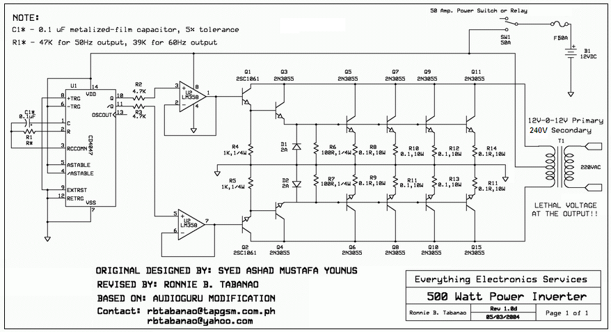
Hi Kennedy,
That 500W inverter had many mistakes. I fixed it two years ago but a moderator there recently changed it so it doesn't work any more. Here is my fixed one. For 1000W it needs many more transistors and 100A from the 12V battery. Its output is a square-wave.
Download Attachment: 500Watts_Inverter-small.PNG
161.27 KB
 |
|
|
|
ovuriri
Apprentece
10 Posts |
Posted - Feb 13 2007 : 06:48:13 AM
|
| Hello mr.audioguru,i am so happy!!!!!!i cant express my gratitude,but audioguru,what if i replace the 2n3055 bjt transistors with mosfet transistors,will it be okay?i love very much.have a lovely day...kenny |
|
|
|
audioguru
Nobel Prize Winner
Canada
4218 Posts |
Posted - Feb 13 2007 : 2:59:20 PM
|
| This power inverter uses ordinary cheap transistors because Mosfets are not available everywhere. Mosfets are much better but the circuit for them must be completely different. |
|
|
|
Topic |
|