| Author |
 Topic Topic  |
|
audioguru
Nobel Prize Winner

Canada
4218 Posts |
 Posted - Apr 25 2009 : 10:02:40 AM Posted - Apr 25 2009 : 10:02:40 AM


|
Hi Dimestone,
Your circuit will not work:
1) The collectors of the transistors do not have a a DC connection to the transformer so they will not do anything.
2) Capacitors C1 and C2 still have backwards polarity.
3) R3 and R4 still do not provide the transistors with enough base current.
4) D1 and D2 will short-circuit the transformer when the voltage at each end tries to rise to +23V.
5) R5 and R6 make no sense and would just reduce the current from Q2.
6) The voltage rating of your capacitors is too low. In the original project capacitors C1 and C2 charge to about 23V. Use 50V capacitors.
5) |
 |
|
|
dimestone
Apprentece

USA
6 Posts |
Posted - Apr 26 2009 : 02:20:46 AM


|
Reply to Admin audioguru
Hi Dimestone,
Your circuit will not work:
1) The collectors of the transistors do not have a a DC connection to the transformer so they will not do anything.
Reply
This is a complete circuit doing work, maybe no useful work until it is put to its intended use of AC power production.
2) Capacitors C1 and C2 still have backwards polarity.
Oddly enough, in a Greinacher multiplier, Crofton/Walton, or cascade multiplier, here is a Marx Generator which is same http://www.instructables.com/id/High_Voltage_Power_Supply_For_Marx_Generator/ AC to DC, DC multiplier the polarity is such that the hot wire of the AC input power passes from the positive side of the Capacitor down the cascade and the reverse flow of the AC current is hindered by the diode arrangement, the neutral side of the AC power input acts as the dc negative or ground. All my head can rap around after building one of these and using it is that in making a dc to ac inverter is that it doesn't matter so long as it is 60 cycles/sec to and fro here in North America.
This is an excerpt from the Wiki on inverters electrical from my previous post, Aaron's attempt to make a more sinusoidal wave form is mentioned in the article falling under the section 'Advanced Designs', the section is just below.
Multilevel inverters provide another approach to harmonic cancellation. Multilevel inverters provide an output waveform that exhibits multiple steps at several voltage levels. For example, it is possible to produce a more sinusoidal wave by having split-rail direct current inputs at two voltages, or positive and negative inputs with a central ground. By connecting the inverter output terminals in sequence between the positive rail and ground, the positive rail and the negative rail, the ground rail and the negative rail, then both to the ground rail, a stepped waveform is generated at the inverter output. This is an example of a three level inverter: the two voltages and ground. [3]
It is also mention in the the article that, "after current passes a capacitor all previous waveforms are canceled."
Beyond this here a few more to look at?
Below :Positive flow resistance variance electron flow resistor diodes
This one I named after audioguru, Are we there yet? hot potato cold potato. Are we ready for a new component list, do we need one, do you have some nice software? I have free nationwide calling including Canada and Mexico?
Here's what I'm after?
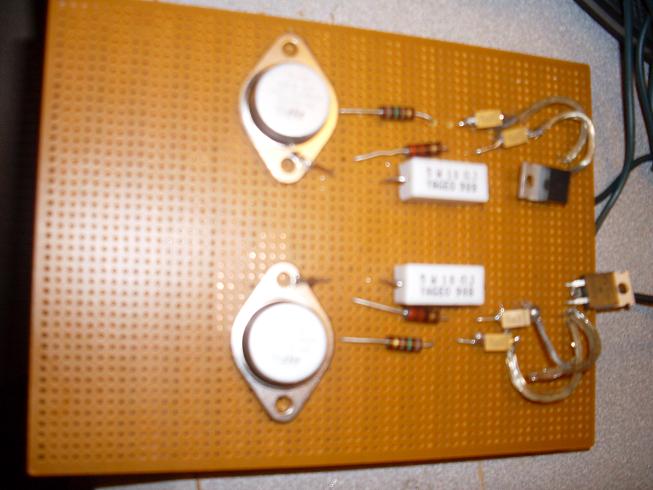
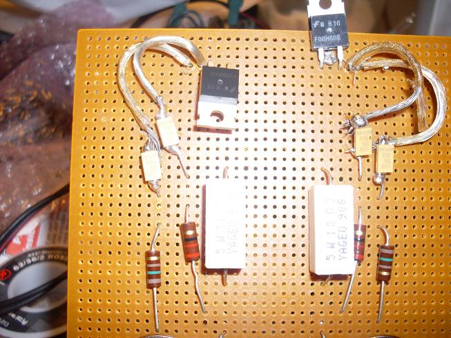
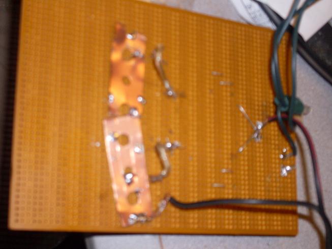
Here are some pictures of the circuit above, but in its real built state, with a few discrepancies, I'll try it all before it's over. It didn't work, it didn't do anything, more importantly it did not blow up anything. As of yet I did not try to take a voltage reading after the two power related diodes, it was raining last night and didn't want to push my luck more than yet. Yes though, last night I did have a diode in place after the collectors on the ground side at the copper strips I'm using for circuit material.
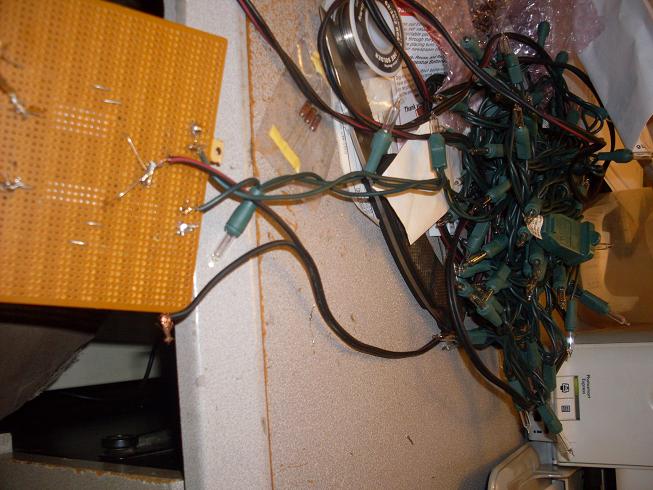
If I do the schematic at bottom of this thread but use these 220uF 400v photo capacitors, where do you think we will be? but but wait there's more audioguru check this http://www.electro-tech-online.com/alternative-energy/86777-grid-tie-inverter-schematic-3.html this guy is offering up free info at this other board on how to build grid tie inverters, he said he is putting together some DIY cd's showing how to do his grid tie inverters. The info he offered up is later on in that grid tie inverter forum. IDK, maybe you've see it already, but still cool none the less.
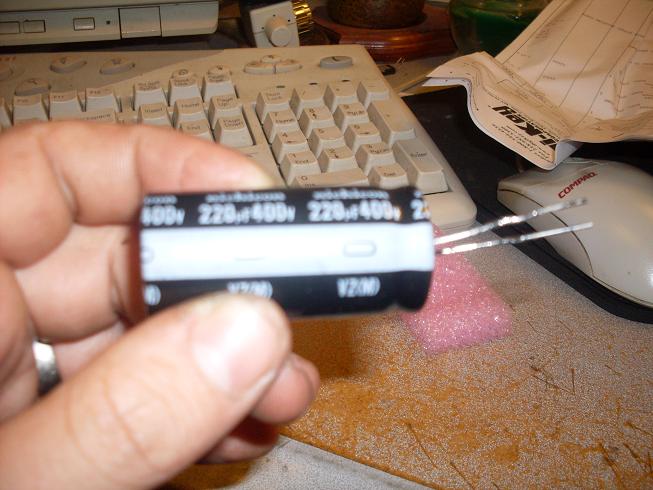
$19.95, it's no wonder, a capacitor and toothpic!
3) R3 and R4 still do not provide the transistors with enough base current.
I don't know about your battery, my batter has 7800 Watts stored. 12v and 650 amps on demand.
We are starting out with 650 cranking amps in a lot of batteries, I have read manuals for several dc to ac power inverters and have discovered that they start out with a draw of only 380 miliamps.
Starting with 12v and taking a path through these resistors I get using I=E/R I=12v/10ohm I=1.2 amps, I'm not saying that this is the only path that positive electron flow will occur.
4) D1 and D2 will short-circuit the transformer when the voltage at each end tries to rise to +23V.
What voltage would that be? This is a DC circuit, would you be making a reference to AC electricity that will have almost zero potential when dealing with a silicon diode.
5) R5 and R6 make no sense and would just reduce the current from Q2.
This circuit won't wait for these little guys, but somehow man does make the universe try to conform as to be of some use. If you want to, you can try and find another similarly rated component to do the job, if there is a such an animal. I took a 1000, what will you take, I suggest 1200, 1400, 1700, 2000, maybe 4700, 7000, 10000, 11000, none of that is proven though till we try.
6) The voltage rating of your capacitors is too low. In the original project capacitors C1 and C2 charge to about 23V. Use 50V capacitors.
Yes, there were two capacitors in Aaron's shematic, they were both rated at 60v. Let's see 60+60=120, I have provided 4 capacitors rated at 33v, so 33+33+33+33=132, I have more volts.
Using Ohm's law given half the resistance across the circuit and the circuit joined with every component of this circuit, this model shows above 50 volts.
Voltage 12 volts
Current 1.2 amps
Resistance 1 10 ohms
Power 14.4 watts
Voltage 46.475800154489 volts
Current 0.30983866769659335 amps
Resistance 2 150 ohms
Power 14.4 watts
Voltage 48 volts
Current 0.3 amps
Resistance 1+2 160 ohms
Power 14.4 watts
Voltage 51.1937496184837 volts
Current 0.28128433856309726 amps
Resistance1+2+3 182 ohms
Power 14.4 watts
5)
Besides jumping from an airplane, is there anything else? If it wasn't addressed you shouldn't mention it cause I'm on a tight budget here.
Go to Top of Page |
Edited by - dimestone on May 06 2009 08:26:47 AM |
|
|
|
audioguru
Nobel Prize Winner
Canada
4218 Posts |
Posted - Apr 26 2009 : 09:57:53 AM
|
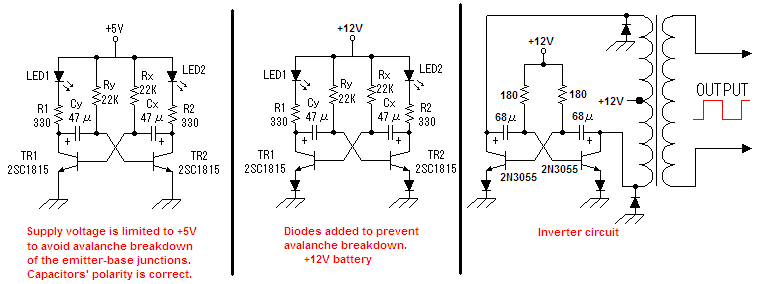
I copied a transistor multivibrator circuit that blinks LEDs. Its supply voltage is limited to 5V to avoid avalanche breakdown of the emitter-base junctions of its transistors . Thier emitter-base junctions have a max allowed voltage of 5V.
The 2N3055 power transistors in this inverter project have a max allowed emitter-base voltage of 7V so in my second schematic I added diodes in series with the emitters.
In my third schematic I have this inverter with diodes added in series with the emitters and protection diodes added differently to the collectors of the transistors.
The base current is only (12V - 0.8V)/180 ohms= 62mA. A 2N3055 transistor saturates pretty well if its collector current is 2A when its base current is only 62mA. Then the power from the battery is 12V x 2A= 24W and the output power from the inverter is a little less.
The 2N3055 transistors need driver transistors.
Download Attachment:  inverter circuit.PNG inverter circuit.PNG
18.66 KB
 |
|
|
|
audioguru
Nobel Prize Winner
Canada
4218 Posts |
Posted - Apr 26 2009 : 4:41:59 PM
|
Hi Dimestone,
Nobody sees anything good about your modifications that won't work.
This project was probably started about 50 years ago but used PNP germanium transistors which explains the backwards capacitors. Germanium transistors did not have a low voltage emitter-base avalanche breakdown. |
|
|
|
audioguru
Nobel Prize Winner
Canada
4218 Posts |
Posted - Apr 26 2009 : 6:03:14 PM
|
Hi Dimestone,
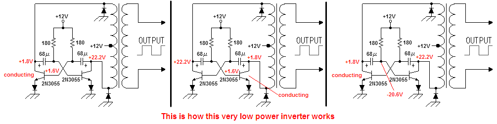
Never mind changing this hopeless inverter circuit around. If it is fixed then its output power is very low.
This is how it will work if it is fixed:
Download Attachment: inverter circuit again and again.PNG
19.41 KB
 |
|
|
|
dimestone
Apprentece
USA
6 Posts |
Posted - Apr 27 2009 : 04:41:34 AM
|
quote:
Originally posted by audioguru
Hi Dimestone,
Never mind changing this hopeless inverter circuit around. If it is fixed then its output power is very low.
This is how it will work if it is fixed:
Download Attachment: inverter circuit again and again.PNG
19.41�KB
My momma told me since I can remember that I was the "Icing on the cake." I'm building a prototype at the moment, I have to let the iron warm up. |
|
|
|
Justinjustin
Apprentece
10 Posts |
Posted - May 18 2009 : 05:13:45 AM
|
quote:
Originally posted by audioguru
Hi Kennedy,
That 500W inverter had many mistakes. I fixed it two years ago but a moderator there recently changed it so it doesn't work any more. Here is my fixed one. For 1000W it needs many more transistors and 100A from the 12V battery. Its output is a square-wave.
Download Attachment: 500Watts_Inverter-small.PNG
161.27�KB
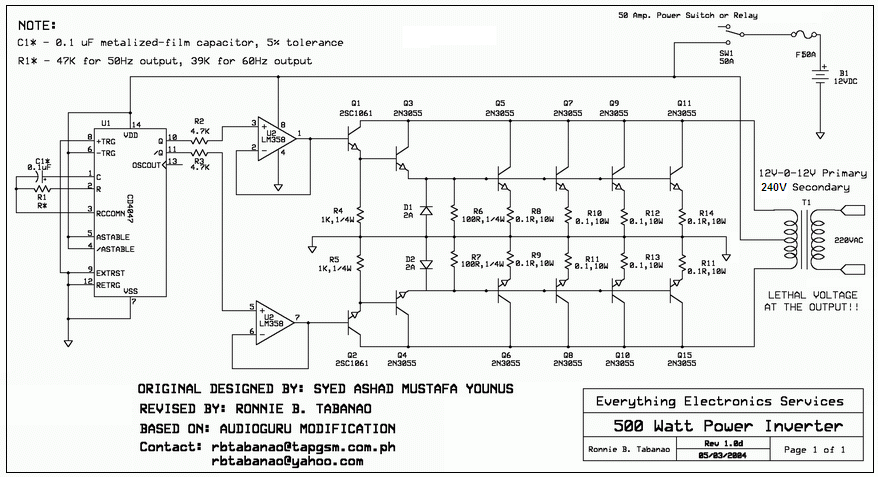
Hi, audio Guru,
this is the one I am using, I want to know the VArating of the transformer. and Can transformer use reverse? |
|
|
|
audioguru
Nobel Prize Winner
Canada
4218 Posts |
Posted - May 18 2009 : 6:38:27 PM
|
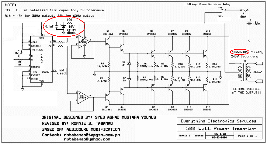
That is a very old inverter that was originally designed in China.
It uses many old 2N3055 transistors because modern Mosfets were not available there.
I fixed it so that it could be used in The Philippines where poor people do not have any electricity.
It has a square-wave output. Many electronic products do not work properly with a square-wave.
Sometimes a transformer can be used in reverse if it has enough inductance.
The output power is 500W so the transformer should be 600VA.
It was recently improved with a zener diode and a change in the transformer voltage.
Download Attachment: 500w inverter final again.PNG
151.1 KB
 |
|
|
|
Dino_25
New Member
2 Posts |
Posted - May 20 2009 : 03:47:20 AM
|
I normally tinker around with simple RF receivers, low power TX, and audio-- inverters are fairly new to me. I thought I'd throw this piece of crap together to see what would happen. Well... It DID work... for about 30 seconds with a 75W bulb, then I found myself cleaning up electroylitic acid. I tried once more, but made various changes. I paralleled 2 more 3055's, added diodes in series with the transistor's bases with a couple of resistors to ground to turn the transistors off, and added some zener diodes in place of the 10 ohm resistors and diodes on the xfrmr. It helped a little. I ran a 75 watt bulb for a whole 1 min, 30 secs before it died. So I scrapped it.
Later, I read about an even simpler inverter circuit by Harry Lythall. Here's the link to the article http://web.telia.com/~u85920178/. I was skepticle, so I threw the thing together, powered it up, and heard the old familiar buzz. I conneted two 20watt flourescent bulbs and the thing worked. I left it on for about 30 minutes with no problems. The transistors actually didn't get that hot with no heatsink at all, but I connected a small fan to blow cool air on them just to be sure. I wouldn't dare try and connect my laptop to it though.
I CAN say, however, that the circuit on aaron's site works... for a few seconds, followed by explosions. Maybe there are ways to improve it (like audioguru suggested), but it would just be too much of a headache. For anyone who is looking for a permanent power back-up, just buy a cheap inverter off ebay or find a better designed circuit to work with. Or if you have a couple of uninteruptable power supplies (UPS), like I do, they work just fine. I have 2 small APC BK400 250W UPS's. I found them at a thrift store for $2.00 a piece !!! I use one to power a small 55 watt tv and playstation during outages. !!! I use one to power a small 55 watt tv and playstation during outages.
I would go for audioguru's redesigned 500W inverter. It looks like a great circuit. And if anyone has difficulty find the CD4047 IC, jameco.com has them for about $0.29 a piece. |
If it ain't broke, don't fix it! |
|
|
|
Dino_25
New Member
2 Posts |
Posted - May 20 2009 : 03:50:47 AM
|
| Sorry about the Jameco link... I must've screwed up. It should be easy enough to just enter www.jameco.com into your browser. |
If it ain't broke, don't fix it! |
|
|
|
Alberto
Apprentece
23 Posts |
Posted - Jun 29 2009 : 8:27:14 PM
|
| I guess I joined too late. I�ve been reading this topic and replies from the start and the more I read the more I get confused. That�s just because Me ( and anybody who joins late ) doesn�t know WHICH schematic ALL of you are rfering to. So, why can�t everybody attach their schematic when you post, either a questio or an answer. Thanks. |
|
|
|
Alberto
Apprentece
23 Posts |
Posted - Jun 29 2009 : 9:07:59 PM
|
Sorry, everybody. I guess I posted when I shouldn�t. I started reading this thread from the BEGINNING.
Although I did SMILE and LAUGH sometimes, I�m getting more confused. I try to solve my problems by myself before, read all threads and posts and then ask my SPECIFIC questions. But it seems that a lot of us could go crazy if we�re not sure about WHICH schematic we are discussing: The original, rvised, corrected, functional, etc.
I strongly advise that whenever you post refer to THE schematic you�re talking about. I hoe this helps EVERYBODY! |
|
|
|
audioguru
Nobel Prize Winner
Canada
4218 Posts |
Posted - Jun 30 2009 : 8:31:49 PM
|
This thread is about the inverter circuit that has the polarity of its capacitors backwards so they blow up.
It also has the max allowed emitter-base voltage of the transistors exceeded so they also blow up the capacitors even if their polarity is correct.
The base current of the transistors is much too low so that they need driver transistors.
The circuit is a joke. |
|
|
|
Alberto
Apprentece
23 Posts |
Posted - Jul 01 2009 : 5:36:59 PM
|
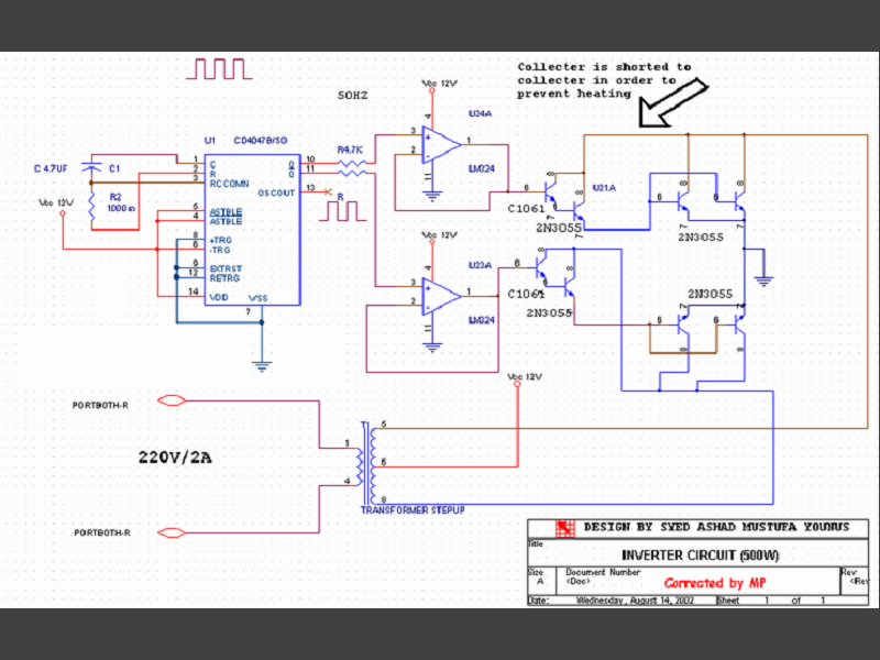
Excuse me audioguru. I�m going through this thread from the beginning ( 2004 ) and the forum mentions too many schematics. Anyway, have you ever discussed this one. If so could you direct to where it began. If not, how about your opinion and any suggestions. Thanks.
Download Attachment: New Drawing.PNG
147.62 KB |
|
|
|
audioguru
Nobel Prize Winner
Canada
4218 Posts |
Posted - Jul 02 2009 : 09:24:58 AM
|
Hi Alberto,
The circuit you found was "corrected by MP" but he made many errors:
1)It doesn't have enough output transistors for 500W output. Each 2N3055 output transistor has an absolute max allowed current of 15A but performs poorly above 10A. But with a 500W load each output transistor must pass 25A.
2) Its 2n3055 transistors must be matched.
3) There are no protection diodes to arrest voltage spikes.
4) The resistor R2 in the CD4047 oscillator is only 1k ohms but Texas Instruments says it should be a minimum of 10k.
5) The timing capacitor in the CD4047 oscillator is way too high at 4.7uF and a low tolerance capacitor cannot be found with such a high value.
6) It doesn't have a fuse to stop a fire.
7) It uses two LM324 quad opamps instead of just a single LM358 dual opamp.
8) Its output is a square-wave without voltage regulation.
9) It does not shut down when the battery voltage gets low.
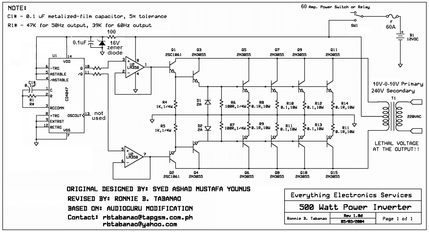
I fixed it and it is used in 3rd-world countries. It would be much better if a Mosfet circuit replaced the 2N3055 transistors but Mosfets are rare in 3rd-world countries. It would also be better if gates were added to make it have a "modified sine-wave" output waveform. We discussed the gates, shutdown when the battery gets low and even discussed voltage regulation in this and other threads.
Here is my fixed version of the 500W inverter:
Download Attachment: 500W inverter final.PNG
86.17 KB
 |
|
|
|
Topic |
|
|
|
 New Drawing.PNG