| Author |
 Topic Topic  |
|
audioguru
Nobel Prize Winner

Canada
4218 Posts |
 Posted - Jul 03 2009 : 7:06:02 PM Posted - Jul 03 2009 : 7:06:02 PM


|
I am sorry that you live in a weird country.
Here everything works because they were planned properly in advance. |
 |
|
|
tabish abbas
Apprentece

Pakistan
8 Posts |
|
|
audioguru
Nobel Prize Winner
Canada
4218 Posts |
Posted - Jul 11 2009 : 10:58:00 AM
|
The 100W inverter has a square-wave output that does not have voltage regulation.
Will your load work from a square-wave?
Will your load care if the voltage is too high when the battery is charged then the voltage is too low when the battery is discharged?
Will your battery be able to supply 10A? |
|
|
|
jeffreywong
Member

32 Posts |
Posted - Jan 13 2010 : 10:14:28 AM
|
quote:
Originally posted by audioguru
It is easy to make a sine-wave oscillator that has low output power. If you feed it to a power amplifier then the amplifier will make a lot of heat and most of the battery power will be wasted.
It is easy to convert a square-wave to a sine-wave at low power.
A sine-wave inverter uses a high frequency oscillator, a small high frequency transformer and Mosfets to make a suitable high voltage then rectifies and filters it. Then it uses a microcontroller to make pulse-width-modulation at 50Hz or 60Hz and feeds an H-bridge with high voltage switching Mosfets that produce the sine-wave with many steps in it, then two small high frequency filters. Negative feedback is used to regulate the output voltage. A shutdown circuit works during over-current, over-temperature and low battery voltage.
Hi, audioguru, Im doing a pure sine wave inverter, im facing many proble during working on it, i need u assist on it.
1. Can I using SG3526 to generate a PWM instead of microcontroller?
2. If so, If I generate high frequency PWM to switch, how can I use a lowpass filter to change back to 50HZ output? I have try to change it back to 50HZ, but fail to do it, can u teach me?
3. High frequency transformer is very difficult to find, can rewind it by myself by using toroidal core?
4. If i rewind by myself, I fail to search the spec. of the 12V to 240V , 25A tranformer. Do u have anyidea?
Thanks... |
|
|
|
audioguru
Nobel Prize Winner
Canada
4218 Posts |
Posted - Jan 13 2010 : 11:30:36 AM
|
quote:
Originally posted by jeffreywong
Im doing a pure sine wave inverter, im facing many problems during working on it, i need u assist on it.
1. Can I using SG3526 to generate a PWM instead of microcontroller?
I have never seen an inverter because my electricity is reliable. I have also never seen an SG3526 IC. I can buy a cheap Chinese sine-wave inverter that uses two TL494 PWM ICs.
quote:
2. If so, If I generate high frequency PWM to switch, how can I use a lowpass filter to change back to 50HZ output? I have try to change it back to 50HZ, but fail to do it, can u teach me?
You must modulate the PWM with a 50Hz sine-wave.
The lowpass filter is an inductor in series and a capacitor to ground. Simple.
quote:
3. High frequency transformer is very difficult to find, can rewind it by myself by using toroidal core?
I don't know where you will find a ferrite core that does not saturate with the high current in its coil.
quote:
4. If i rewind by myself, I fail to search the spec. of the 12V to 240V , 25A tranformer. Do u have anyidea?
I don't know the spec's of a high frequency power transformer. |
Edited by - audioguru on Jan 13 2010 11:31:45 AM |
|
|
|
jeffreywong
Member
32 Posts |
Posted - Jan 14 2010 : 04:10:48 AM
|
quote:
Originally posted by audioguru
It is easy to make a sine-wave oscillator that has low output power. If you feed it to a power amplifier then the amplifier will make a lot of heat and most of the battery power will be wasted.
It is easy to convert a square-wave to a sine-wave at low power.
A sine-wave inverter uses a high frequency oscillator, a small high frequency transformer and Mosfets to make a suitable high voltage then rectifies and filters it. Then it uses a microcontroller to make pulse-width-modulation at 50Hz or 60Hz and feeds an H-bridge with high voltage switching Mosfets that produce the sine-wave with many steps in it, then two small high frequency filters. Negative feedback is used to regulate the output voltage. A shutdown circuit works during over-current, over-temperature and low battery voltage.
I have some confusing about it.
What u mean is that a pure sine wave inverter have to transform a 12VDC to 240VDC then use mosfet switches to invert 240VDC to 240VAC.
My question is how can the DC power can run in transformer?
thanks... |
|
|
|
wasssup1990
Nobel Prize Winner
A Land Down Under
2261 Posts |
Posted - Jan 14 2010 : 07:02:47 AM

|
I think you mean 340VDC to 240AC RMS.
A change in voltage on the primary will cause all secondary coils to produce a derivative voltage. If you single out a 10% PWM duty cycle you will see that for 10% of a PWM cycle the primary coil is being energized - current is increasing in the primary so voltage is being induced in all secondaries. If you put a near 100% duty cycle on the primary, each cycle should only just reach the saturation point of the core material used in the transformer - for maximum efficiency.
In case you didn't understand what I just said in the middle of my last paragraph. The DC part can be confusing to Noobs because it isn't a constant DC. The current on the primary goes from 0 Amps up to V/R where R is the resistance of the coil. So even though you have pulsed a constant voltage across the primary, the primary DC is increasing from 0 Amps over time which in so doing induces a voltage in all secondary coils. I suggest you go and open an electronics book. You'll learn a lot more and a lot quicker than any of us can teach you. Just like everything in the universe, a change of some sort is needed to do any kind of action. The same with transformers - a stepped constant voltage causes a change in current in any kind of medium which conducts electricity until it reaches a maxima of V/R. I could go on and on...
Happy thinking  |
When one person suffers from a delusion it is called insanity.
When many people suffer from a delusion it is called religion. |
Edited by - wasssup1990 on Jan 14 2010 07:11:09 AM |
|
|
|
jeffreywong
Member
32 Posts |
Posted - Jan 14 2010 : 9:04:24 PM
|
quote:
Originally posted by audioguru
It is easy to make a sine-wave oscillator that has low output power. If you feed it to a power amplifier then the amplifier will make a lot of heat and most of the battery power will be wasted.
It is easy to convert a square-wave to a sine-wave at low power.
A sine-wave inverter uses a high frequency oscillator, a small high frequency transformer and Mosfets to make a suitable high voltage then rectifies and filters it. Then it uses a microcontroller to make pulse-width-modulation at 50Hz or 60Hz and feeds an H-bridge with high voltage switching Mosfets that produce the sine-wave with many steps in it, then two small high frequency filters. Negative feedback is used to regulate the output voltage. A shutdown circuit works during over-current, over-temperature and low battery voltage.
I have some confuse.
In the last part, you said that it use a microcontroller to generate a 50HZ PWM to drive the switches, so why it still need a high frequency filter to filter it since the PWM generate is only 50HZ?
thanks... |
|
|
|
wasssup1990
Nobel Prize Winner
A Land Down Under
2261 Posts |
Posted - Jan 15 2010 : 12:53:28 AM
|
OMG Jeffrey go and read some electronics books. Do you not understand how PWM works? You're modulating the width of a pulse with a sine 50Hz. The cycle length of a single PWM cycle should be several times smaller in order to reproduce the modulating wave form in PWM. The filter is designed to oscilate at 50Hz and will not pass the PWM frequency of which should be several times higher than the 50Hz modulating signal.
Is it a language barrier for you? I don't know. |
When one person suffers from a delusion it is called insanity.
When many people suffer from a delusion it is called religion. |
|
|
|
audioguru
Nobel Prize Winner
Canada
4218 Posts |
Posted - Jan 15 2010 : 6:20:34 PM
|
We speak English here. I don't know why people from the other side of the world come here when they "no speeky zee engrish".
The power oscillator that steps up the 12V to 340V is at a high frequency so so a small ferrite high frequency transformer is used.
The high frequency is modulated by a 50Hz sine-wave. The modulated high frequency drives the Mosfet H-bridge and an LC filters out the high frequency switching carrier frequency. |
Edited by - audioguru on Jan 15 2010 6:24:48 PM |
|
|
|
wasssup1990
Nobel Prize Winner
A Land Down Under
2261 Posts |
Posted - Jan 15 2010 : 8:08:13 PM
|
| We're just walking in circles now. |
When one person suffers from a delusion it is called insanity.
When many people suffer from a delusion it is called religion. |
|
|
|
abdulgtm
Apprentece
12 Posts |
Posted - Jan 17 2010 : 02:14:33 AM
|
Dear <
Still have u completed ur project or pending , let me know may I becmae help u in this regard
Abdul |
|
|
|
sb5_csn
New Member
4 Posts |
Posted - Jan 01 2016 : 10:37:24 PM
|
sir, due to connecting"CD4001 ic" over heating in ic is occured. please, give a solution in this page.
|
|
|
|
audioguru
Nobel Prize Winner
Canada
4218 Posts |
Posted - Jan 02 2016 : 09:23:08 AM
|
quote:
Originally posted by sb5_csn
sir, due to connecting"CD4001 ic" over heating in ic is occured. please, give a solution in this page.
I do not know the circuit you have that uses a CD4001 IC. Please post the schematic.
The datasheet from Texas Instruments shows the typical output current.
When the IC uses a 5V supply its maximum output current is only a few mA, maybe 5mA per output when shorted. Then the IC heats with 5mA x 4 x 5V= 0.1W and it will be warm. ARE YOU SHORTING ALL 4 OUTPUTS?
When the IC uses a 10V supply its maximum output current is about 22mA per output when shorted. Then the IC heats with 22mA x 4 x 10V= 0.88W which will burn it.
When it has a high impedance load (another CMOS input) then it does not heat up. What is it driving?
|
|
|
|
audioguru
Nobel Prize Winner
Canada
4218 Posts |
Posted - Jan 02 2016 : 09:50:10 AM
|
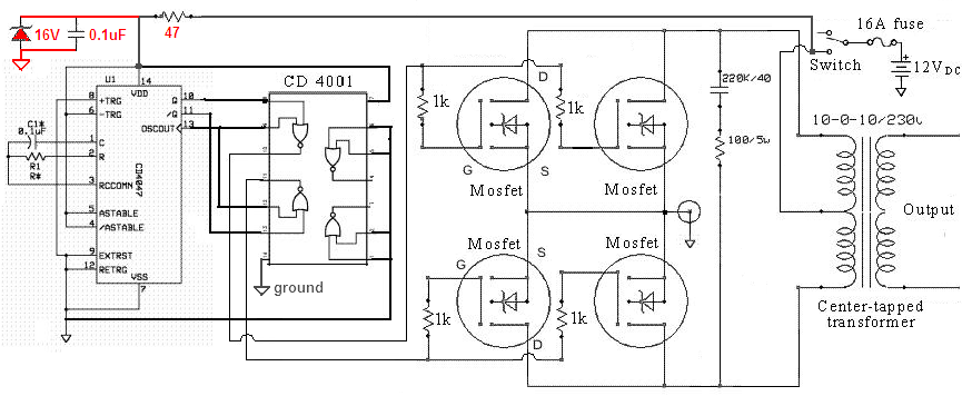
The circuit that was posted in this thread 8 years ago uses a CD4001 Cmos logic IC powered from a 12V battery and it drives Mosfets that have no input current. The frequency is low and the current is extremely low so the CD4001 IC does not get warm.
Maybe the circuit is missing the resistor feeding a zener diode and capacitor as shown here and voltage spikes have destroyed the IC?
Download Attachment:  modified sinewave inverter.png modified sinewave inverter.png
118.96�KB |
Edited by - audioguru on Jan 02 2016 9:52:59 PM |
|
|
|
Topic |
|
 modified sinewave inverter.png