| Author |
 Topic Topic  |
|
kivdenn
Nobel Prize Winner

Uganda
535 Posts |
 Posted - Dec 16 2009 : 10:25:12 AM Posted - Dec 16 2009 : 10:25:12 AM


|
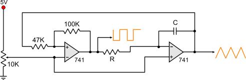
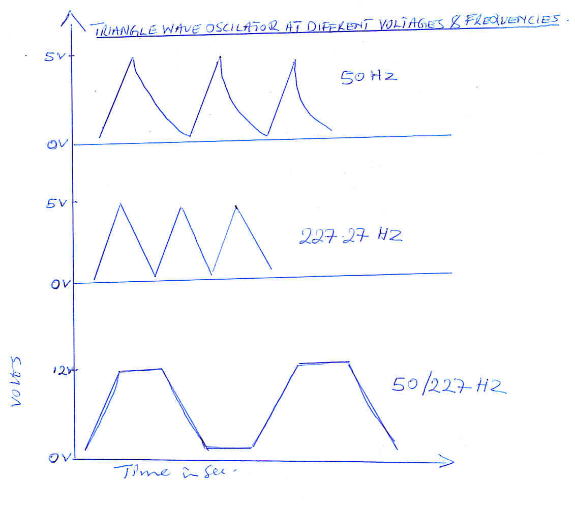
Hi all, i got this triangle wave oscilator from http://pcbheaven.com/circuitpages/Triangle_Wave_Generator/ , the author says he built it using a 5v supply but can run on any voltage as long as it doesnt exceed the rated voltage of the OPAMP ICs. I also built it using a 13v supply at 50hz but it gave a funy wave which looks like a triangle wave but has got flat end both on top and the bottom. When I changed it to operate on 5V it gave a good triangle wave at 227.27hz but when I reduced the frequency to 50hz by changing the value of R to 100k the wave developed straight ups and curved downs. I want to use this oscilator on the MSW inverter with stable output but I fear the curved triangle waves might negatively affect the overall invewrter output. For that reason please help try to make this wave a clean triangle wave at 50hz when the circuit is hooked on a 13v power supply. Thanks Dennis
Download Attachment:  trianglewavegenerator_1246552290.jpg trianglewavegenerator_1246552290.jpg
10.86 KB
Download Attachment: Oscilator output.jpg
70.89 KB
 |
|
|
audioguru
Nobel Prize Winner
Canada
4218 Posts |
Posted - Dec 16 2009 : 11:46:17 AM
|
The 741 opamp was designed for operating with ONLY a 30V supply. Many will not work properly if the supply is less than 10V and most will not work with a 5V supply.
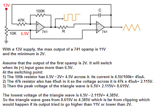
With a 13V supply, its max output voltage is 11V and its minimum output voltage is 2V if its load is 10k ohms and more.
With the 47k input resistor and 100k feedback resistor, the first opamp will switch when the peaks of the triangle wave are much less than the clipping voltages of 11V and 2V as shown in my sketch.
Maybe you got the 47k and 100k resistors mixed up, then the output of the triangle wave will be clipped top and bottom.
Download Attachment: triangle wave generator again.PNG
44 KB
 |
 |
|
|
kivdenn
Nobel Prize Winner
Uganda
535 Posts |
Posted - Dec 17 2009 : 05:45:22 AM
|
| Hi Audioguru am new to this, please try to soften the technical language. I need this oscilator to peoduce a clean triangle wave of 50HZ at the battery voltage of 10.5v to 14V. What do you think needs to be changed to achieve this? Thanks |
|
|
|
audioguru
Nobel Prize Winner
Canada
4218 Posts |
Posted - Dec 17 2009 : 10:48:27 AM
|
I showed you why it should work fine if the opamps are 741 or better and if you used the correct resistor values.
If you got the 47k and 100k resistors swapped then the output will have flat spots (clipped) on the top and bottom of thr triangle waves. The output will also be clipped if the load is lower than 2k ohms.
1) Which opamp?
2) What resistor values?
3) What is the load resistance? |
|
|
|
kivdenn
Nobel Prize Winner
Uganda
535 Posts |
Posted - Dec 18 2009 : 01:59:50 AM
|
I have tried to change from LM741 to LM071 but the results where the same, I have also mesured the resistor values with a multmetre and it reads 46.98K and 100.02K for the 47k and 100k resitors respectively. I dont understand what you mean by load resistence could you please elaborate more on what load resistence is.
Another question, since this oscilator generates a clean triangle wave on a 5v power supply, can it work well on the 'MSW inverter circuit with stable out put'? because then, I can just regulate the power supply to the 741 IC to 5V with LM7805 or a 5V zener in series with a 1k resistor.Thanks
Dennis |
Edited by - kivdenn on Dec 18 2009 02:13:37 AM |
|
|
|
audioguru
Nobel Prize Winner
Canada
4218 Posts |
Posted - Dec 18 2009 : 09:22:07 AM
|
quote:
Originally posted by kivdenn
I have tried to change from LM741 to LM071 but the results where the same
Nobody makes an LM071. Maybe you used a TL071. Maybe you connected +13V and 0V and the inputs and output to the wrong pins. If you post the entire detailed schematic you used then we can see.
quote:
I have also mesured the resistor values with a multmetre and it reads 46.98K and 100.02K for the 47k and 100k resitors respectively.
Then with a 13V supply and a load resistance of 2k ohms or more, the peaks of the triangle wave should be at 4.39V and 8.6V like I showed and will not be clipped. Did you connect the resistors backwards?
quote:
I dont understand what you mean by load resistence
It is the resistance that is driven by the output of the second opamp. An opamp cannot drive a load resistance that is less than 2k ohms. You have so many threads here that I don't know what will be driven by the triangle wave.
quote:
since this oscilator generates a clean triangle wave on a 5v power supply, can it work well on the 'MSW inverter circuit with stable out put'? because then, I can just regulate the power supply to the 741 IC to 5V with LM7805 or a 5V zener in series with a 1k resistor.
Before you said with a 5V supply and a 50Hz frequency it didn't work properly. Now it works? What changed?
Like i said earlier, the lousy old 741 opamp is not designed to work with a supply as low as only 5V. Some 741 opamps don't work with a supply as low as 10V.
The minimum supply voltage for a TL071 is 7V. |
|
|
|
kivdenn
Nobel Prize Winner
Uganda
535 Posts |
Posted - Dec 18 2009 : 09:38:42 AM
|
I think I will have to just give up on this circuit but do you have any other triangle wave oscilator circuit that uses any thing else other than TL082, LM741, Tl071 or LMC555 because i have tried with all these and failed and I badly need to make that MSW DC-AC inverter with stable output but the triangle wave generator circuit seems to have failed me as I cant get the LMC555 all I get is NE555. Thanks
Dennis |
|
|
|
kivdenn
Nobel Prize Winner
Uganda
535 Posts |
|
|
audioguru
Nobel Prize Winner
Canada
4218 Posts |
Posted - Dec 23 2009 : 2:13:15 PM
|
The circuit from Chemelec is exactly the same circuit. Its output triangle wave goes from about 4.4V to about 8.6V and since the peaks are nowhere near 0V or 13V then the output is not clipped unless the output is overloaded with a load resistance that is too low, or if the 47k and 100k resistors are swapped.
I asked "what is the output load?" but you did not say.
A TLC555 or an ICM7555 are exactly the same as an LMC555. They are made by many manufacturers.
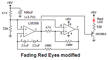
Here is the same circuit that fades LEDs:
Download Attachment: fading LED eyes modified.PNG
7.36 KB
 |
|
|
|
kivdenn
Nobel Prize Winner
Uganda
535 Posts |
Posted - Dec 24 2009 : 04:25:20 AM
|
As I told you before, that I am going to use this circuit in the MSW inverter with stable out project, the out put of the second OPAMP is going to be fed to a TL81 which will then converter it into a square wave that will in turn be fed to the CD4017 to be changed to a modified sine wave. I think the load resistance component here is the TL081 IC but I dont know its resistance. As for the 100k and the 47k resistors I checked and there was not swapping. Do you think the problem could be with my PC Oscilloscope? What will happen if I use a clipped wave ? Thanks
Dennis |
|
|
|
pebe
Nobel Prize Winner
United Kingdom
1078 Posts |
Posted - Dec 24 2009 : 05:12:02 AM
|
| If you are using a PC scope that uses the sound card, don't forget that it can only handle signals up to 5V peak. Any signals greater than that will be clipped by its internal diodes. |
|
|
|
kivdenn
Nobel Prize Winner
Uganda
535 Posts |
Posted - Dec 27 2009 : 07:55:00 AM
|
Hi all, I have discovered what has been failing my circuit I have been using a PC scope and because its maximum voltage is 5V and my circuits have been 13V, there has always been an excess of 7V and that's why my waves have been clipped both at the bottom and top.
However I have used chemelec's triangle wave generator circuit and applied it to our MSW inverter with stable voltage circuit but the results are not what I expected. As you can see bellow the triangle wave generator has worked well and produces good triangle waves at a frequency of 50HZ, this wave is fed into the TL81 OP AMP which converts it into a square wave which is also OK but when this wave is fed into the CD4017 IC the output is a square wave at half the frequency of the triangle wave. I expected to generate a modified sine wave at a 50HZ frequency. What could be the cause of this. NB. for the two 2n2f capacitors i used ceramic caps with these writings 2A103H. The radio shark told me that they are 2n2f but I doubted him, could they be the cause of this failure? Thanks Dennis
OOOPS the images are once again failing to upload MR. Modorator what could be the problem? |
Edited by - kivdenn on Dec 27 2009 08:03:40 AM |
|
|
|
audioguru
Nobel Prize Winner
Canada
4218 Posts |
Posted - Dec 27 2009 : 11:15:05 AM
|
Chemelec's circuit uses only one timing capacitor like most of the other triangle-wave circuits, not two. Ceramic capacitors usually have a very wide tolerance of their value. If you don't know its value then you should throw it away. You should use a 5% film capacitor.
I cannot remember the MSW circuit but maybe the TL081 opamp is being used as a comparator to produce pulse-width-modulation. The TL081 opamp has a problem of "Phase-Inversion" when its input voltage is too close to the ground voltage (within about 3V or 4V). Then its output frequency is doubled. |
|
|
|
kivdenn
Nobel Prize Winner
Uganda
535 Posts |
Posted - Dec 28 2009 : 05:16:31 AM
|
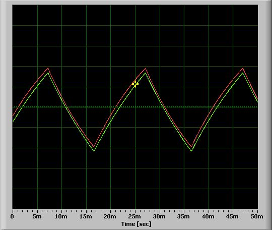
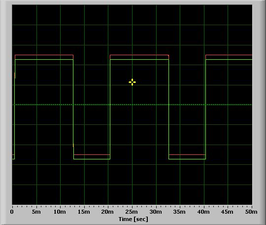
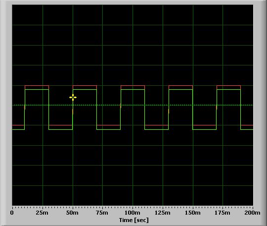
I have finaly manged to upload the images. Its funny mozila firefox cant upload the images but internet explorer does. Any way here are the PC osciloscope images of the triangle wave output at pin 7 of TL082 and the square wave output at pin 6 of Tl081 and the funny square wave output at the decoded outputs 1&3 of CD4017 which is 25HZ (half the frequency of the triangle wave output of 50HZ at pin7 of TL082) The caps I was talking about are the two caps at the clock and Clock Enable pins of CD4017 IC. Why do you think was the cause of this deviation in the results? Remember am using a PC scope. Thanks Dennis
Download Attachment: Output at pin7 of TL082.jpg
38.58�KB
Download Attachment: Output at pin6 of TL081.jpg
35.44�KB
Download Attachment: Output at pins 2 and 7 of CD4017.jpg
33.85�KB
Download Attachment: Correct MSW Stable voltage.gif
10.25 KB
|
Edited by - kivdenn on Dec 28 2009 05:27:59 AM |
|
|
|
audioguru
Nobel Prize Winner
Canada
4218 Posts |
Posted - Dec 28 2009 : 1:21:15 PM
|
Your "scope" is awful:
1) The triangle wave is supposed to have perfectly straight sides instead of curved.
2) The square-wave is supposed to be perfectly square instead of rectangular. |
|
|
|
pebe
Nobel Prize Winner
United Kingdom
1078 Posts |
Posted - Dec 29 2009 : 06:18:54 AM
|
......TL081.....TL082......?
What circuit are you talking about? I see neither of these ICs in any of your circuits. |
|
|
|
Topic |
|