| Author |
 Topic Topic  |
|
pebe
Nobel Prize Winner

United Kingdom
1078 Posts |
 Posted - Sep 27 2014 : 10:52:41 AM Posted - Sep 27 2014 : 10:52:41 AM


|
I have now �digested� the rest of your posting about the 4060s, and hope this will answer your questions.
quote:
That is why I could not make heads or tails, I confused �T� and the resulting time delays did not match. Or am I still missing something?
'T' in the formula T = 2.2 x C x R refers to the period of the waveform of the oscillator, ie. the time taken for the oscillator to complete one cycle (I can explain the 2.2 if you want). That formula holds true for a CD4060 or an HCF4060. The counter gets a pulse from the oscillator, and increments the count every Tsecs. So it counts to Q9 after 2^9 pulses, Tsecs apart. So to calculate C x R to get a time delay of XXsecs before Q9 goes high the formula would be:
XXsecs / 2^9 = 2.2 x C x R. Therefore, C x R = XXsecs / (2^9 x 2.2)
quote:
To achieve the C2 and R2 component values required I feel more confident using F = 1 / 2.2 R2 C2 and T = 2n / F, maybe because I prefer to consider T as being the required time delay and not the time interval between successive clock pulses
I cannot see where you get the expression �2n� from. But I think you can see from the above that is easier to think in terms of Time rather than Frequency, because it makes calculating a delay period much easier.
Regarding a 300sec delay before a 5sec timed period. It would be possible to use a 4060 to get a 300sec delay period before Q9 goes high, but it would require several other Q pins (equal to 5secs) to go high and then gated in and Q9 gated out so that after a further 5secs, the oscillator would be stopped. It�s not a very practical arrangement.
A better method would be to use two 4060s. The first (CC1) one would count to give a 295sec delay while a diode from Q9 (low) to the second 4060 (CC2) would stop its oscillator and prevent it counting.
After 295sec , CC1 a diode would stop its oscillator as before, and the diode feed to CC2 would then allow CC2 to count. After a further 5secs one of its outputs would go high to give a pulse for 5secs before its oscillator was disabled. The result would be a 300sec delay before a 5sec ON pulse, then OFF. I hope that explains it, but if not I�ll draw up a circuit.
In your circuit I am puzzled by the relay having a contact that bridges S1 when the relay is on. That implies that S1 is only closed for a short period � a pulse, perhaps? If so how does the 12V supply get power during the delay period before the relay switches on?
|
 |
|
|
snarf
Apprentece

Malta
26 Posts |
Posted - Sep 27 2014 : 11:59:29 AM
|
quote:
Originally posted by pebe
Thanks for your reply. There is a lot for me to go through with the 4060; I'll deal with it as soon as I can.
Meanwhile for the 555 circuit, the only thing I can think of for the failures when you use tantalums is that they have a high leakage current. That's not a feature of tants - quite the opposite, in fact. Could you have inadvertently wired them in with reversed polarity? That would certainly cause a high leakage current.
The polarity marks are quite small, so here is a link explaining them:
http://www.learningaboutelectronics.com/Articles/Tantalum-capacitor-polarity-markings
Many thanks for your kind assistance and patience. Sorry for writing so much but I thought it necessary to try and explain myself better.
From my little understanding I was not expecting tantalums to act in that way either and that is why I asked the questions.
The polarity is correct, in fact that was one of the first things I had checked, even though I am very careful about polarity. Difficult to confuse though as the tantalums I have are marked with the positive sign (+) and have uneven sized leads. In fact they look like the one in the first picture of the link provided and have the same type of markings. Thank you for the link.
The strangest aspect of all this is that if C4 10�F tantalum capacitor is replaced with a 10�F electrolytic capacitor the circuit is OK.
I am trying to understand your reply regarding the 4060 and hope to be able to reply soon.
|
Edited by - snarf on Sep 27 2014 12:01:32 PM |
|
|
|
snarf
Apprentece
Malta
26 Posts |
Posted - Sep 27 2014 : 3:09:31 PM
|
Thank you for your kind assistance.
quote:
'T' in the formula T = 2.2 x C x R refers to the period of the waveform of the oscillator, ie. the time taken for the oscillator to complete one cycle (I can explain the 2.2 if you want). That formula holds true for a CD4060 or an HCF4060. The counter gets a pulse from the oscillator, and increments the count every Tsecs. So it counts to Q9 after 2^9 pulses, Tsecs apart. So to calculate C x R to get a time delay of XXsecs before Q9 goes high the formula would be:
XXsecs / 2^9 = 2.2 x C x R. Therefore, C x R = XXsecs / (2^9 x 2.2)
OK thanks for re-explaining, I understand the formula better now. I don�t think it�s necessary to explain the 2.2 it�s a fixed parameter like the 1.1 in the 555�s formula and the explanation may be too complicated for me to understand at this stage. What confuses me is why others use different parameters such as 2.5 instead of 2.2, when 2.2 is clearly indicated in the data sheets.
quote:
quote:
________________________________________
To achieve the C2 and R2 component values required I feel more confident using F = 1 / 2.2 R2 C2 and T = 2n / F, maybe because I prefer to consider T as being the required time delay and not the time interval between successive clock pulses
________________________________________
I cannot see where you get the expression �2n� from.
On 20 September I said.
quote:
For the timing calculation I used F = 2n / T.
T is in seconds
F is in hertz
R is in ohms
C is in farads
n is the Q number (2^n meaning 2 for n number of times)
Where I explained what I am understanding what the terms mean, with �n� being the �Q� number. Therefore 2n = 2^Q, and 2^Q is the same as you indicted in your formula explanation.
For clarity I got F = 1 / 2.2 R2 C2 from the HCF4060 data sheet (F ~ 1 / 2.2 Rt Ct) and I got T = 2n / F (or T = 2^Q / F) form the searches I made on the internet.
quote:
But I think you can see from the above that is easier to think in terms of Time rather than Frequency, because it makes calculating a delay period much easier.
I agree it�s much easer to think in terms of time now that I am understanding a bit better.
quote:
Regarding a 300sec delay before a 5sec timed period. It would be possible to use a 4060 to get a 300sec delay period before Q9 goes high, but it would require several other Q pins (equal to 5secs) to go high and then gated in and Q9 gated out so that after a further 5secs, the oscillator would be stopped. It�s not a very practical arrangement.
When on 21 September you said �the circuit will need revising� I was trying to figure out how this can be achieved, but since the timing is higher for each successive �Q� number and the timing pulse (5 seconds) is lower then the delay period (300 seconds) this is going to be difficult. If it was the other way round (that is 5 seconds and then 300 seconds) that would be easier to accomplish. So I came to a dead end.
quote:
A better method would be to use two 4060s. The first (CC1) one would count to give a 295sec delay while a diode from Q9 (low) to the second 4060 (CC2) would stop its oscillator and prevent it counting.
After 295sec , CC1 a diode would stop its oscillator as before, and the diode feed to CC2 would then allow CC2 to count. After a further 5secs one of its outputs would go high to give a pulse for 5secs before its oscillator was disabled. The result would be a 300sec delay before a 5sec ON pulse, then OFF. I hope that explains it, but if not I�ll draw up a circuit.
I think I follow but if it�s not asking for too much a circuit will help.
quote:
In your circuit I am puzzled by the relay having a contact that bridges S1 when the relay is on. That implies that S1 is only closed for a short period � a pulse, perhaps? If so how does the 12V supply get power during the delay period before the relay switches on?
I am aware that S1 has confused you and sorry if I tend not to explain myself properly. As I tried to explain on 24 September S1 is normally OFF (open contacts) as indicated in STAGE 1. When S1 comes ON (closed contacts) as indicated in STAGE 2, it gives power to the DC power supply thereby activating the timer circuit and S1 remains closed during the whole 300 seconds delay. When the timer relay RL1 is activated and the 5 seconds ON pulse starts the indicated LOAD is being switched ON by RL1-2 contacts and in turn this LOAD is switching S1 OFF (open contacts) as indicated in STAGE 3. But RL1-1 contacts have also closed and have bridged S1 so the DC power supply remains ON until the 5 seconds pulse has ended, as indicated in STAGE 4. Whereby when the 5 seconds pulse ends the relay contacts RL1-1 and RL1-2 open and turns OFF the DC power supply and the LOAD. S1 is already OFF (open contacts) so everything has returned to the OFF state as indicated in STAGE 1.
In more simple terms yes S1 is closed for the duration of the whole 300 seconds, therefore the 12V supply remains active during the 300 seconds delay by S1 and continues to remain active by the relay RL1-1 contacts during the 5 seconds pulse. S1 is activated automatically by a remote electrical (mains) system. The LOAD indicated in the circuit will turn S1 OFF, we can say resetting S1. But this LOAD must remain active for 5 seconds. At the end of the 5 seconds pulse S1, DC power supply, timer, LOAD have to be in the OFF state and ready for lets say the next cycle.
Since S1 is not important for the timer circuit I would ignore it and go back to my initial statement of the circuit being switched ON when the DC source is present. On the other hand I will be pleased to answer any queries you may have.
|
|
|
|
pebe
Nobel Prize Winner
United Kingdom
1078 Posts |
Posted - Sep 29 2014 : 06:52:12 AM
|
Sorry about the 2n thing - I completely missed it in your explanation.
I did not realize that S1 was closed for 300secs then open again. That could possibly used to generate the 300sec delay circuit. Is the switch on some form of appliance? Can you let me know whether it can be isolated from the mains supply? |
|
|
|
snarf
Apprentece
Malta
26 Posts |
Posted - Sep 29 2014 : 2:41:28 PM
|
Thanks for reply.
quote:
Sorry about the 2n thing - I completely missed it in your explanation.
No problem, I re-explained.
quote:
I did not realize that S1 was closed for 300secs then open again. That could possibly used to generate the 300sec delay circuit. Is the switch on some form of appliance? Can you let me know whether it can be isolated from the mains supply?
The switch S1 may still be confusing you. The switch S1 does not have a delay circuit. The switch S1 is part of an electrical circuit and not an appliance. No it can�t be isolated from the mains supply directly. It can only be isolated be adding a relay, meaning S1 will control the relay and this relay will in turn control the timer circuit, which does not make much sense when S1 can control the timer circuit directly.
It is the timer circuit we are talking about that will give the delay for how long S1 will remain closed. So the delay (300 seconds) plus the ON Pulse (5 seconds) is made by the timer and not by the electrical circuit. Without the timer circuit the mentioned electrical circuit will not function.
Your 2 by 555s circuit does what is required (a delay and an ON pulse), the problem was that high delay periods was hard to achieve because high value tantalums would be required and apart from being expensive are not available locally. That is when you suggested using the 4060 instead.
Is it possible to achieve the same function as the 2 by 555 circuit with the 4060?
Meaning, timer circuit activated by DC power, OFF delay of 300 seconds after which an ON pulse of 5 seconds (relay ON period), and then OFF.
|
|
|
|
pebe
Nobel Prize Winner
United Kingdom
1078 Posts |
Posted - Sep 30 2014 : 07:13:01 AM
|
quote:
The switch S1 may still be confusing you. The switch S1 does not have a delay circuit. The switch S1 is part of an electrical circuit and not an appliance. ��
��Without the timer circuit the mentioned electrical circuit will not function.
I am still confused. That sounds like a dog chasing its own tail. As I understand it, S1 switches on for a duration of 300sec (it is unaffected by adding a timer). Is that right? If so I was considering using that period as the delay timer, ie. the 5sec pulse could be made to start when the S1 has closed and then opened again at the end of 300secs.
It would make the circuit very simple if S1 could be disconnected from the mains supply.
It would help my understanding if I knew exactly what S1 was.
|
|
|
|
snarf
Apprentece
Malta
26 Posts |
Posted - Sep 30 2014 : 1:28:17 PM
|
quote:
��Without the timer circuit the mentioned electrical circuit will not function.
Sorry I meant to write ��..will not function as required.� my mistake.
quote:
As I understand it, S1 switches on for a duration of 300sec (it is unaffected by adding a timer). Is that right?
No as I tried to explain on 24th September I included the switch S1 in the circuit to show that something is giving power to the timer circuit. Please note my initial posts whereby I stated �Timer on by DC power ON and not by a switch�.
quote:
The switch S1 in the circuit is more or less symbolic and to show that one set of relay contacts in the timer circuit is bridging the remote switch S1 (relay contacts RL1-1) to maintain the DC power supply ON until the whole timing cycle has ended, because S1 will open once the second set of relay contacts in the timer circuit has given power to the LOAD (relay contacts RL1-2).
The switch S1 as shown in the circuit does not exist, does not switch on for 300 seconds and it can be affected by adding a timer.
quote:
If so I was considering using that period as the delay timer, ie. the 5sec pulse could be made to start when the S1 has closed and then opened again at the end of 300secs.
Yes that would have been easier but it is not possible as there is NO switch S1 and there is no other 300 seconds delay. It is the timer circuit which will be switched on by DC Power ON that will give the required 300 seconds delay and the 5 seconds pulse.
quote:
It would make the circuit very simple if S1 could be disconnected from the mains supply.
Agreed but it�s not possible as switch S1 does not exist.
quote:
It would help my understanding if I knew exactly what S1 was.
The imaginary switch S1 is the electrical mains (240V) which is being turned ON by the previously mentioned electrical circuit which comes ON automatically when a particular condition exists, and remains ON indefinitely unless it is controlled. Which means, provides a usable 240V output ONLY when that condition exists and there is no switch S1 which can be isolated or controlled. Remember my initial request for timer circuit ON by DC Power ON.
I will try to explain in hopefully simpler terms. As an example lets say we have a light bulb which will be switched ON when a sensor has been activated. But it will come ON and remain ON, and that is not what we would want.
What we want is that when the sensor has been activated we have a delay of 300 seconds before the light bulb is switched ON and that this light bulb is ON for only 5 seconds. After which everything resets to OFF.
One solution would be to have a timer controlling the sensor output to the light bulb. Practically that is the basic idea.
I made a mistake by including switch S1 in the circuit as it has caused unnecessary confusion which was not my intention.
The 2 by 555s circuit does what is needed but with C1 = 100�F (the highest value I could find) and R1 = 2M the delay is 220 seconds and not the required 300 seconds.
Can you please help with a similar circuit using the 4060, thanks.
|
Edited by - snarf on Sep 30 2014 1:33:01 PM |
|
|
|
pebe
Nobel Prize Winner
United Kingdom
1078 Posts |
Posted - Oct 01 2014 : 11:56:34 AM
|
quote:
The imaginary switch S1 is the electrical mains (240V) which is being turned ON by the previously mentioned electrical circuit which comes ON automatically when a particular condition exists, and remains ON indefinitely unless it is controlled��
Does the 5sec pulse turn it off? If not, what is the �control� that turns it off?
quote:
Can you please help with a similar circuit using the 4060, thanks.
OK, I�ll draw up a circuit. It is a simple circuit but will require 2 x 4060s.
|
|
|
|
pebe
Nobel Prize Winner
United Kingdom
1078 Posts |
Posted - Oct 01 2014 : 2:52:39 PM
|
It cannot be done with a single 4060. I could have given you a circuit that used one 4060 and one 4082 dual AND, but the gating was messy and you could not adjust the times individually. So here is the circuit with two 4060s. With this circuit each of the times can be individually set by the VR pots. IC1 is the 300sec delay timer. IC2 is the 5sec timer.
At startup, C1 is discharged and puts a high on the resets of both ICs, resetting them. IC1-Q14 is low so there is no output. D2 pulls down pin11 of IC2 and stops its oscillator. IC2-Q14 is low and via R3 charges C1 to take off the reset. D1 is reverse biased so has no effect on IC1-pin11, so it starts to count.
After 300secs IC1-Q14 will go high and there is now an output. D2 is now reverse biased so IC2 will start to count. After a further 5secs, IC2-Q14 will go high taking the resets high and resetting both counters and taking all Qs and the output low.
So when the ICs are powered up, there will be a delay of 300secs with no output. Then the output will go high for 5secs and then low again. I assume the relay contact takes the power off so the counters cannot repeat.
I hope you find that to be OK.
(Edit) You don't need D1, so leave it out.
Download Attachment:  4060.GIF 4060.GIF
15.64�KB
 |
Edited by - pebe on Oct 01 2014 2:56:18 PM |
|
|
|
snarf
Apprentece
Malta
26 Posts |
Posted - Oct 02 2014 : 12:29:36 PM
|
Sorry for late reply.
quote:
Does the 5sec pulse turn it off? If not, what is the �control� that turns it off?
Yes it does, when the 5 seconds pulse STARTS the relay is turned ON and when the 5 seconds pulse ENDS the relay is turned OFF. Thereby one set of relay contacts will be turning the timer�s circuit Power OFF, remember the relay contacts bridging the so called S1.
quote:
OK, I�ll draw up a circuit. It is a simple circuit but will require 2 x 4060s.
quote:
It cannot be done with a single 4060. I could have given you a circuit that used one 4060 and one 4082 dual AND, but the gating was messy and you could not adjust the times individually. So here is the circuit with two 4060s.
Thank you so much for both the circuit and detailed circuit explanation. I should have the 4060 in hand tomorrow or Saturday and then first I will assemble the circuit on a breadboard, after which I will get back with a reply.
I could have never managed to make this circuit myself, maybe in time, thanks again.
quote:
With this circuit each of the times can be individually set by the VR pots. IC1 is the 300sec delay timer. IC2 is the 5sec timer.
Agreed, it�s always better to have individual time settings.
quote:
I assume the relay contact takes the power off so the counters cannot repeat.
Your assumptions are correct, one set of relay contacts will be taking the Power OFF, therefore it should not repeat. But if it does maybe because the timer circuit resets before the relay physically turns OFF (electro mechanical is slower compared with electronic), can a diode (similar to what we had in the 4060 5sec by 5sec circuit) be included to stop the counter from repeating until the relay has turned OFF?
quote:
(Edit) You don't need D1, so leave it out.
OK no problem, but what would have been the function of D1?
When I posted my revised circuit I forgot to include the 100�F capacitor across the DC source, sorry for the omission.
|
Edited by - snarf on Oct 02 2014 12:34:04 PM |
|
|
|
pebe
Nobel Prize Winner
United Kingdom
1078 Posts |
Posted - Oct 03 2014 : 5:14:20 PM
|
quote:
quote:�Does the 5sec pulse turn it off? If not, what is the �control� that turns it off?�
Yes it does, when the 5 seconds pulse STARTS the relay is turned ON and when the 5 seconds pulse ENDS the relay is turned OFF. Thereby one set of relay contacts will be turning the timer�s circuit Power OFF, remember the relay contacts bridging the so called S1.
I can see how the relay operates. My question was: how is the 240V mains turned off?
quote:
Your assumptions are correct, one set of relay contacts will be taking the Power OFF, therefore it should not repeat. But if it does maybe because the timer circuit resets before the relay physically turns OFF (electro mechanical is slower compared with electronic), can a diode (similar to what we had in the 4060 5sec by 5sec circuit) be included to stop the counter from repeating until the relay has turned OFF?
When the relay turns off the power, the two ICs will have been reset, so even if the power does not go off immediately and the counters start again, it will take 300secs before the relay can switch on again.
quote:
When I posted my revised circuit I forgot to include the 100�F capacitor across the DC source, sorry for the omission.
As there is no interruption of the supply voltage during both counts, you can reduce the 100�F cap across the supply to 10�F min. But as both oscillators are running during the 5sec time, add a 100nF cap across supply near pins 8 and 16 to prevent common coupling between them due to short spikes on the supply rail.
|
|
|
|
snarf
Apprentece
Malta
26 Posts |
Posted - Oct 04 2014 : 4:40:16 PM
|
quote:
quote:
________________________________________
quote:�Does the 5sec pulse turn it off? If not, what is the �control� that turns it off?�
Yes it does, when the 5 seconds pulse STARTS the relay is turned ON and when the 5 seconds pulse ENDS the relay is turned OFF. Thereby one set of relay contacts will be turning the timer�s circuit Power OFF, remember the relay contacts bridging the so called S1.
________________________________________
I can see how the relay operates. My question was: how is the 240V mains turned off?
Sorry I misunderstood. During the 5 seconds pulse the indicated LOAD will be switched ON. This LOAD circuit is controlled by a contactor which we can say also controls the 240V mains to the other electrical circuit (the so called switch S1). Therefore the timer relay will switch ON the LOAD contactor (for those 5 seconds pulse) giving power (240V) to the LOAD and at the same time this LOAD contactor switches OFF the 240V mains to the other electrical circuit (the so called switch S1) thereby resetting the electrical circuit and it�s output to the timer circuit is also switched OFF.
Therefore when the timer cycle ENDS and the timer relay is switched OFF the timer circuit has NO power, so it�s switched OFF. At the same time the LOAD contactor is also being switched OFF by the timer relay. With the LOAD contactor switched OFF the electrical circuit (the so called switch S1) again has power (240V) but it�s not active (not giving an output). The timer circuit will be switched ON again when the electrical circuit (the so called switch S1) again becomes active (gives an output) due to meeting one of the electrical circuit conditions in which case the process repeats again.
quote:
quote:
________________________________________
Your assumptions are correct, one set of relay contacts will be taking the Power OFF, therefore it should not repeat. But if it does maybe because the timer circuit resets before the relay physically turns OFF (electro mechanical is slower compared with electronic), can a diode (similar to what we had in the 4060 5sec by 5sec circuit) be included to stop the counter from repeating until the relay has turned OFF?
________________________________________
When the relay turns off the power, the two ICs will have been reset, so even if the power does not go off immediately and the counters start again, it will take 300secs before the relay can switch on again.
OK I understand but just for the sake of learning something else can the circuit be stopped from repeating, similar to what happens in the 2 by 555�s circuit?
quote:
quote:
________________________________________
When I posted my revised circuit I forgot to include the 100�F capacitor across the DC source, sorry for the omission.
________________________________________
As there is no interruption of the supply voltage during both counts, you can reduce the 100�F cap across the supply to 10�F min.
OK but if I leave C4 at 100�F it should still be alright?
quote:
But as both oscillators are running during the 5sec time, add a 100nF cap across supply near pins 8 and 16 to prevent common coupling between them due to short spikes on the supply rail.
Sorry I�m not sure if I understand, you mean one 100nF capacitor between +12V and 0V for each IC or only one 100nF for both IC�s? That would mean in parallel with C4, right?
Download Attachment: CD4060-CMOS-pinout.jpg
27.8 KB
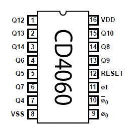
I don't understand what you mean by �near pins 8 and 16� ? The pins are physically opposite each other and if it�s only one 100nF capacitor that needs adding near which IC should I add it?
I got the 4060�s today, I will do my best to assemble tomorrow and hopefully post by latest on Monday.
|
|
|
|
pebe
Nobel Prize Winner
United Kingdom
1078 Posts |
Posted - Oct 05 2014 : 08:22:45 AM
|
quote:
OK I understand but just for the sake of learning something else can the circuit be stopped from repeating, similar to what happens in the 2 by 555�s circuit?
The oscillator cannot run without a power supply, but assuming there was power, then taking pin11 of IC1 high or low would stop its oscillator. With its Q14 low there is no way either of the ICs could count.
quote:
OK but if I leave C4 at 100�F it should still be alright?
Yes, no problem.
quote:
Sorry I�m not sure if I understand, you mean one 100nF capacitor between +12V and 0V for each IC or only one 100nF for both IC�s? That would mean in parallel with C4, right?
and
I don't understand what you mean by �near pins 8 and 16� ? The pins are physically opposite each other and if it�s only one 100nF capacitor that needs adding near which IC should I add it?
I will try to explain. If you look at the data sheet for the 4060, it shows a block diagram of what is inside the IC. It consists of an oscillator driving a number of �2 counters. The output of each counter consists of a complimentary pair of FETs; one switches the output to Vdd and the other switches it to Vss, as appropriate. As the output changes over, there is a very brief period when both FETs are switched on together and so they create a low resistance across the supply. The result is a brief increase in supply current that tends to lower the voltage between Vdd and Vss.
The wiring from the power supply to the ICs has inherent inductance that will try to prevent this increased current and so Vdd would drop during these very short pulses. In addition, the electrolytic cap used to smooth the supply will also have an inherent series resistance, so it will not effectively provide the short pulses of current necessary to maintain Vdd.
The answer is to use one of the �poly� capacitors that have very low internal resistance across the supply, mounted as close as possible to the ICs to avoid the supply line inductance effects. Provided both ICs are fairly close to one another, then a single 100nF will be sufficient.
I hope that explains it OK.
|
|
|
|
snarf
Apprentece
Malta
26 Posts |
Posted - Oct 06 2014 : 1:07:42 PM
|
Both 4060 circuits have been assembled on a breadboard and tried out. I refer to the revised circuit I posted and Pebe�s 2 by 4060s circuit. The circuits functioned as Pebe outlined but I had some difficulty with the 2 by 4060s circuit as outlined below.
Please explain the difference between the RC circuits represented by Fig 1 and Fig 2.
Download Attachment: Image 2.JPG
10.42�KB
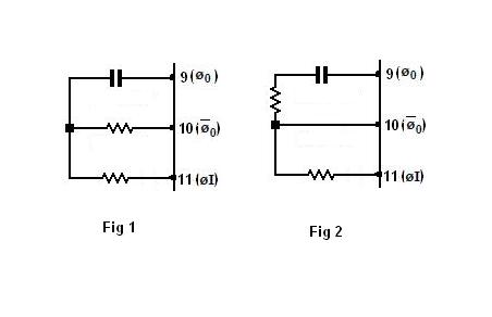
The RC circuit in the 2 by 4060s circuit is represented by Fig 2. The timer circuit did not function with this RC configuration. Therefore I changed the RC configuration as represented in Fig 1 and the timer circuit functioned properly. I�m a bit confused can you please explain?
quote:
quote:
________________________________________
OK I understand but just for the sake of learning something else can the circuit be stopped from repeating, similar to what happens in the 2 by 555�s circuit?
________________________________________
The oscillator cannot run without a power supply, but assuming there was power, then taking pin11 of IC1 high or low would stop its oscillator. With its Q14 low there is no way either of the ICs could count.
Understood, and I have been trying to figure out how it can be done in the 2 by 4060s circuit. Can we take the output from Q14 of IC2 and feed it to pin 11 of IC1 maybe with a diode to drive IC1 pin 11 high, and modify the IC�s counter resetting to reset only IC2?
If it�s the wrong approach please explain how to make pin 11 of IC1 go low or high when the 5 seconds pulse ends.
quote:
I will try to explain. If you look at the data sheet for the 4060, it shows a block diagram of what is inside the IC. It consists of an oscillator driving a number of �2 counters. The output of each counter consists of a complimentary pair of FETs; one switches the output to Vdd and the other switches it to Vss, as appropriate. As the output changes over, there is a very brief period when both FETs are switched on together and so they create a low resistance across the supply. The result is a brief increase in supply current that tends to lower the voltage between Vdd and Vss.
The wiring from the power supply to the ICs has inherent inductance that will try to prevent this increased current and so Vdd would drop during these very short pulses. In addition, the electrolytic cap used to smooth the supply will also have an inherent series resistance, so it will not effectively provide the short pulses of current necessary to maintain Vdd.
The answer is to use one of the �poly� capacitors that have very low internal resistance across the supply, mounted as close as possible to the ICs to avoid the supply line inductance effects. Provided both ICs are fairly close to one another, then a single 100nF will be sufficient.
Thank you for the detailed explanation. As you may have noted I do read data sheets but that does not mean that I understand everything explained in the data sheets. Please remember that my knowledge and experience are very limited.
Therefore it�s best to use �poly� capacitors and not �ceramic� capacitors because �ceramic� capacitors have a higher internal resistance?
For my breadboard trial I used two 100nF capacitors as on the breadboard it was difficult to mount the ICs close to one another.
quote:
At startup, C1 is discharged and puts a high on the resets of both ICs, resetting them. IC1-Q14 is low so there is no output. D2 pulls down pin11 of IC2 and stops its oscillator. IC2-Q14 is low and via R3 charges C1 to take off the reset. D1 is reverse biased so has no effect on IC1-pin11, so it starts to count.
We had D1 removed from the circuit because it was not needed. For the sake of learning did D1 have any particular function or just not required?
|
Edited by - snarf on Oct 06 2014 1:10:47 PM |
|
|
|
pebe
Nobel Prize Winner
United Kingdom
1078 Posts |
Posted - Oct 07 2014 : 08:14:33 AM
|
quote:
The RC circuit in the 2 by 4060s circuit is represented by Fig 2. The timer circuit did not function with this RC configuration. Therefore I changed the RC configuration as represented in Fig 1 and the timer circuit functioned properly. I�m a bit confused can you please explain?
Your Fig 1 is correct �my Fig 2 is wrong. Sorry about that. I must try to remember, �More haste � less speed�
quote:
Understood, and I have been trying to figure out how it can be done in the 2 by 4060s circuit. Can we take the output from Q14 of IC2 and feed it to pin 11 of IC1 maybe with a diode to drive IC1 pin 11 high, and modify the IC�s counter resetting to reset only IC2?
If it�s the wrong approach please explain how to make pin 11 of IC1 go low or high when the 5 seconds pulse ends.
It can be done, but my original circuit will need some changes, so I have now amended it. Here are the changes:
C5 now added and D1 has been restored. VR2 value has been changed, and R3 now connects to 0V instead of to Q14 output.
Now IC1 counts as before but at the end of its count when Q14 goes high, D1 conducts and pulls up pin11 to prevent it counting further. So Q14 stays high. Q14 going high makes D2 reverse biased and so non-conductive. D3 is reversed biased so there is now no control over pin 11 and IC2 counter starts (note that taking pin 11 either high or low will stop the oscillator).
As D3 anode has to be taken high to stop IC2, it is now fed from Q14 output. The 5sec timed output now comes from Q13, so the oscillator has to run at half its original speed. This can be done either by a) increasing VR2 to 47K as shown, or b) adding a 15K to 22K fixed resistor in series with VR2, or c) changing C3 to 22nF. Use whichever method is best for you.
Now with its oscillator running at half speed, Q13 will go high 5secs after the count starts and will give an output (after a total delay of 295 + 5secs). After a further 5secs Q14 will go high, turning on D3 and stopping the oscillator. At the same time Q13 will go low, ending the output. Both counters will stay in that position until the 12V supply is removed.
R4 is added to prevent D3 and D4 conducting if IC1 Q14 goes low and IC2 Q14 goes high together. It should never happen but R4 is there in case.
quote:
Therefore it�s best to use �poly� capacitors and not �ceramic� capacitors because �ceramic� capacitors have a higher internal resistance?
No, it�s a question of stability at varying temperatures. Small ceramics up to about 100pF are very stable, but when you get up to 100nF you have to use a �High K� or a multiplayer ceramic. Neither of these is as stable as a polyester or a polystyrene cap. Although that doesn�t matter for decoupling caps it does matter if you are using them as timing caps. So when it comes to stocking caps for multi purposes, it pays to stock �polys� rather than ceramics, and where I get my supplies from they are cheaper.
quote:
We had D1 removed from the circuit because it was not needed. For the sake of learning did D1 have any particular function or just not required?
In my first circuit it was put in to stop IC1. On reflection I thought it would not be needed because IC1 Q14 only stayed high for 10secs before IC2 output reset both counters via R3. Now, it is necessary to stop IC1 with D1 or else Q14 will toggle up and down every 295secs Q14, clocking IC2 as it does so.
I hope I have explained things well enough.
Download Attachment: 4060-2.GIF
16.73 KB
 |
|
|
|
Topic |
|
|
|