| Home > My Projects > My Electric Razor-Style Scooter |
| Home > My Projects > My Electric Razor-Style Scooter |
Date Of Project: Summer 2003
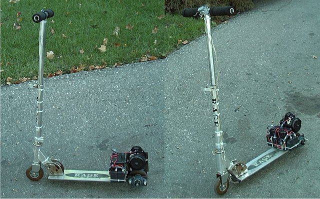
Ever since those I first saw those folding aluminum Razor Scooters, I have been thinking to myself "It would be really neat to put an engine on one". The project was always at the back of my mind, causing me to look twice whenever another kid went whizzing by me on the sidewalk. However, I could not justify the $90 price tag common to those little scooters, and had figured I would pick one up at a yard sale in a few years. As luck would have it, I was driving a friend home from watching a movie at roughly 1:30AM and noticed something glinting at the side of the road. Sure enough, as we passed, I recognized the form as a "Rage" (Razor knock off) scooter. After dropping off my friend, I headed back hoping another passer by had not picked it up. It was still there, and quickly made it's way into my trunk.
After some examination, it was obvious why the scooter was junked. Both the front and rear wheel bearings were destroyed. The seals were missing, most of the balls had fallen out, and the races were running against each other. I guess that just goes to show you what a throw-away society we live in. A quick stop to a bike shop yielded replacement bearings for a whopping $9. Should the bike shop not have had anything in stock, I could have gone to any number of local bearing suppliers and probably found replacements even cheaper. Now that I had a functional scooter, the project could begin.
The first idea to be tossed was the gas engine. Who wants a noisy, smelly, inefficient and complicated 2 stroke engine when a clean, efficient and quiet electric motor could be used instead? I had more then enough suitable motors on hand, and batteries were available from the UPSs we service at work. The only real problem was how to get the power from the motor to the ground. The rear wheel of the scooter is simply mounted on bearings, with no shaft or other method to transfer rotational force to the wheel. While searching one of the many scooter enthusiast websites (Tzi's Scooterworld) I found that most builders use a spindle drive. They mount a rod or pipe to the crankshaft of their engine, and press it against the rear tire. This accomplishes two things: 1. Transfers rotation to the rear wheel; 2. Provides a high gear ratio between the engine and the wheel needed by the small (chainsaw sized) gas engines used. Those little engines don't have any torque, and need ratios of 10:1 or more just to move the scooter. The flaws of this design are the high loss of power between the spindle and the wheel, the slipping caused by dust or moisture, and the extreme wear this puts on the tire. This would simply not do, so I decided to go chain or belt drive. The high torque of the electric motor, combined with the tiny 4" Razor wheels made high gear ratios unnecessary.
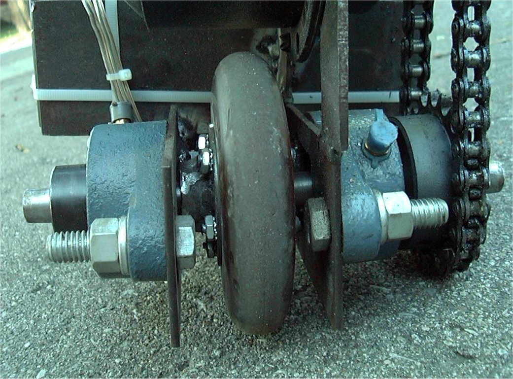 The solution I came up with can be seen here. The existing rear forks were cut off just before they bent slightly inward to grip the wheel. Plates made of 3MM steel were then welded in place, extending the forks and providing an area to mount the bearings. A large hole was cut in the middle of each plate to provide an area for the shaft to pass through. 1/2" flange mount bearings were used, simply mounted with bolts. Instead of nice and round bolt holes, notches were made. One bearing had horizontal notches, while the other used vertical. In this way, when the shaft was driven though, the bearings became self-aligning and assured the wheel would mount up squarely. The shaft itself was simply 6" of hardened tool-steel rod, with a 1/2" diameter to match the bearings. A major problem was the wheel itself. The plastic scooter wheel had a 5/8" bore, and of course no provision to allow it to be locked to a shaft. A few trips to the local bearing store turned up nothing, and the bike shop was another dead end. I was at a local Princess Auto (a auto/surplus store) when I found two key components: 1/2" locking collars, and 1/2" to 5/8" bushings. Perfect! It is hard to see in the picture, but the wheel assembly is as follows. The collar was welded onto a large diameter washer, and 5 holes were drilled around the periphery of the washer. Another matching washer without a collar was drilled to match. The bushings were installed into the wheel, allowing it to sit on a 1/2" shaft. On the left side of the wheel, the washer with the collar was positioned, with the other washer on the right. Five machine screws were then used to clamp the wheel between the washers. Locking nuts were installed on the collar side, with the heads on the opposite side. The result was a wheel with a "thick" and "thin" side, which could easily be locked to it's shaft with the setscrew in the collar. The washer assembly is firmly clamped to the wheel, with the actual weight still concentrated on the center bore. Since the screws pass right through the wheel spokes, any rotation of the shaft is transferred to the wheel. You can click the above picture to get an enlarged view of the rear assembly. Please note that the image is roughly 200K in size.
Assembly of the rear end was straightforward. The shaft fit though the bearing is very tight, so the shaft was put in the freezer for several hours to shrink it as much as possible. The bearings were loosely bolted to the forks, and wheel loosely positioned between them. After placing the shaft into the rightmost bearing, it was driven through with a hammer. As expected, the bearings self-aligned as the shaft was forced through. The assembly turned smoothly, and after the shaft warmed up and the condensation evaporated, both the 20 tooth sprocket (right side) and locking collar (left side) were installed and all set screws tightened.
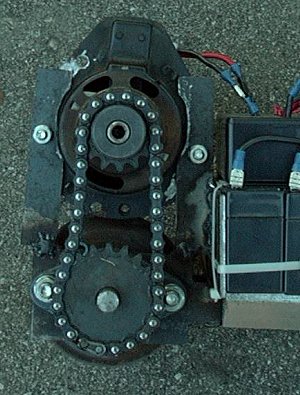 Here you see how the motor was mounted. Two bars were cut and welded to the right fork, and semicircle cutouts formed using a die-grinder. Unfortunately, it seemed that there was a problem. The shaft of the motor measured 8MM in diameter, a truly odd value. In it's previous life, the motor powered the cooling fan of a Pontiac 6000, so I can only assume that GM was not too worried about building a motor using a standard shaft size. Since finding an 8MM sprocket was going to be an impossible task, a local machine shop was able to make an 8MM to 1/2" bushing using a short length of 1/2" steel rod (same as the axle shaft). All in all, the bushing cost $5. Of course, when I asked the machine shop to make an 8MM bore, I should have realized that the bore would be exactly 8MM. Since the motor shaft was also 8MM, the bushing would not slide onto the shaft. To work around this, the motor was put in the freezer for a day, and the bushing heated to 400 degrees prior to being driven onto the motor shaft. It slid on easily, and when cool was secured with a small weld. Obviously, by this time I had decided to use chain instead of belt. It would have been very difficult to find a belt this small, and such a short belt would mean lots of energy wasted in flexing it. Instead, #35 chain was used. The sprocket on the motor has 14 teeth, while the wheel sprocket is a 20 tooth unit. This works out to a gear ratio of about 1:1.5. After the motor was positioned, the chain was cut, sprockets aligned and mounting holes drilled. The motor was secured with two bolts.
As soon as the motor was mounted and the chain joined, it is was greased up and taken for a test ride using a small 12V battery. I would love to say that it was a complete success, but in reality it was quite disappointing. The small battery sagged down to nearly 6V from the 20A draw put on it by the motor, and the scooter just crawled. However, while not a fast trip, it did prove that everything was working. The only issue was that a larger battery was required.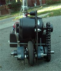
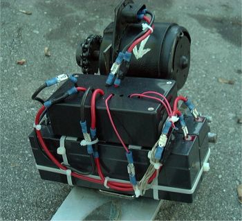 It was decided that two 12V 2.3AH lead-acid gel UPS batteries would be used, mounted slightly in front of the motor. A plate was welded to the forks and motor support, and the batteries secured with zip-ties. Above the batteries, the controller was installed. 3M double sided automotive trim tape (the red stuff, for those who know) was used to secure the controller so that it may easily be removed should there be a change in batteries. This tape is exceptionally strong when applied properly. It is more likely that the controller case will break before the tape gives. As for the controller, it is a simple two speed contactor affair. Two 12V 30A relays inside rearrange the batteries from 12V (parallel) to 24V (series), and a third relay controls power to the motor. When the batteries are in parallel, the current available at 12V doubles. This provides more then enough to start the scooter from a dead stop. The 12V position is also the "slow" position, moving the scooter at around 30KM/H. When in "fast" mode, the controller arranges the batteries in series for 24V. This doubles the speed of the motor and the torque available, almost doubling the speed of the scooter. This puts a lot of stress on the 12V motor, so it can only be used for a short period before the motor must be left to cool down. If you wish to see a schematic of this controller, check out the Simple Two Speed Contactor DC Motor Controller on the Circuits page.
A few weeks after the scooter was finished, I got very tired of the pathetic range available with only 4.6AH of lead. At about that time, a TrippLite UPS arrived at work, DOA from the factory. I pulled the battery, and was happy to find a 12V 5AH battery made by Vision Batteries. It was the CP1250, and measured roughly 3x4x4 inches. Twice the current of my old batteries, and a perfect size. I was able to order 4 of them from a local battery supplier. The new battery pack was mounted in the same place as the old one, ending up twice as tall, but taking no more horizontal space then the old batteries. To make the new pack, I made two "modules" of 12V 10AH by connecting two batteries into "buddie pairs", then connected those pairs in place of the original batteries. I now have a 20AH pack at 12V, and a 10AH pack at 24V. Range with this new pack is around 8KM (roughly 5 miles). The old pack would be well past dead at 1KM. A much more efficient motor would probably result in a range of 10 miles or more.
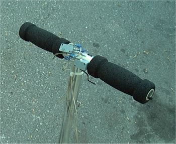 The whole thing is controlled by two trigger switches on the handle bars. These are made from two lever switches. The lever was bent to the proper shape, and the switch secured to the handlebar with 3M tape. The switch on the right handlebar (higher in the picture) is the "go" switch, which activates the relay to connect the motor to the battery. At rest, the batteries are connected constantly in parallel via the normally-closed contacts of the two other switching relays. This means that there is no power drawn, no need for a master "off" switch, and the batteries tend to naturally equalize. The left (lower) switch is the "fast" switch, which activates the two series/parallel relays to configure the batteries for 24V.
Wires to the controller from the switches go down the steering column and through the base of the scooter to prevent them from being snagged. Slack on the 4 conductors used means that the scooter will still fold, and the handlebars can be turned without causing the wires to bind.
Now that this scooter is complete, I have some plans to build another. The next one will be gas (for long range travel). In addition, I have been toying with the idea of building a hybrid gas-electric scooter, which will include a quiet electric motor for indoor and short range operation, as well as a gas engine (that can be started via the electric motor) for long range use, as well as battery charging.
During mid winter of 2004, after I got tired of melting automotive fan motors, I purchased a proper scooter motor. From a seller on eBay I obtained a no-name 350W 36V motor with a 11 tooth #25 sprocket included. This motor is worlds better then the old automotive motors since it has actual sealed ball bearings, much more efficient armature assembly, strong magnets and built in cooling. The old fan motors would generally last about 2 weeks even though I had them highly modified for cooling (drilling vent holes, adding forced air cooling and heatsinking the brushes) and suck large amounts of current during operation. The new motor is very efficient, hardly getting warm even after an hour or more of continuous operation. At the same time the new motor was installed, the axel sprocket was changed to a 30 tooth unit for a gear reduction of about 3:1. This gave the scooter much higher torque and meant that while the top speed was lower then before it could climb any hill around and the motor was operating in a much more efficient RPM range.
A few months after the motor swap, the 4.5AH batteries gave out due to the extreme abuse they suffered under the high current draws of the old motor. The pack was replaced by four 12V 7AH batteries and the pack holder modified to more securely hold the new larger battery pack assembly. With the 12V 28AH/24V 14AH pack I have never been able to drain the batteries as I get tired and beaten up from riding long before the scooter does. I do know that the range is easily 15KM at top speed and in fact probably much more if I had the stamina to keep going.
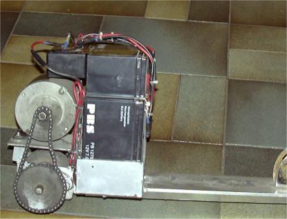
As you can see from the dirt level and the stretch of the chain, this scooter gets a lot of use. It's my primay mode of short-range transportation when the weather is nice and sees semi-daily use.
I've also experimented with running the battery pack at 24V/48V with good results. 48V makes this thing fly at around 60KM/H with enough torque to lift the front wheel off the ground from a rolling start! This is incredibly scary on a tiny Razor scooter with no brakes. The unfortunate part about 48V is that it makes charging the battery pack hard since each battery must be charged separately at 12V to maintain balance. I'm planning to redesign the controller for three speed levels: 12V, 24V and 48V. The 12V position will keep the batteries in parallel when at rest for easy charging.
While the scooter was configured for 48V I made a short burnout video to demonstrate the scooter's power. The video is about 4.6 MB in MPEG format. My Honda Insight makes a guest appearance.
Electric Scooter Burnout Video
Please read the following FAQ before emailing me about this project. It may answer your question. The FAQ is updated based on common questions I receive via email.