| Home > RX-7 > My RX-7 > Project Tina > July 18th, 2007: Finishing The Big Turbo Installation and First Startup |
| Home > RX-7 > My RX-7 > Project Tina > July 18th, 2007: Finishing The Big Turbo Installation and First Startup |
It's that time again. Yes, time for another update on my ongoing (but nearly complete!) turbo-NA bridgeport project. Of course, after the last update, it should now be known as the "big turbo-NA bridgeport project". As the last thread primarily dealt with fabricating an exhaust manifold to mount up the GT4088R, it's well into the big turbo category now.
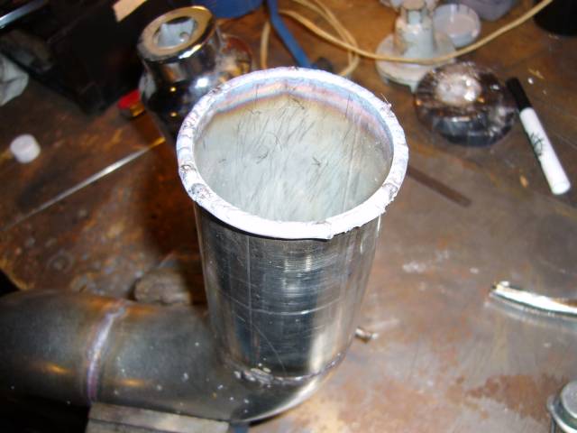
We left off last time after finish welding the turbo outlet pipe. Welding rod was used to form a lip to prevent the coupler from blowing off. This was some tricky welding at very lower current levels.
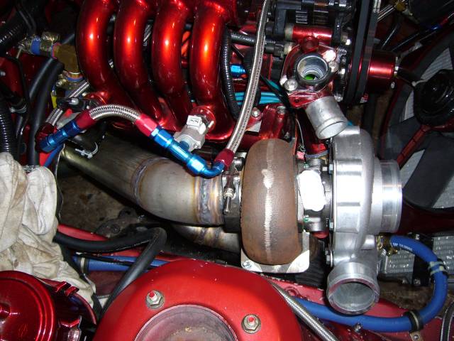
Now that the outlet pipe was complete, the downpipe was the next task. Here's the first section welded onto the 3" V-band and clamped to the turbo. This section allows the V-band flange to match up with the 3" SCH 10 pipe used to make the downpipe. Yes, I said SCH10 pipe. Now before everyone yells "Pipe! It's so thick and heavy. Ghetto! Fail! FTL!" I should mention that while it is a bit heavier then most aftermarket downpipes, it's not nearly as heavy as you would think. We'll get to the exact weight later and I'll point out why I chose to use SCH 10 pipe instead of the more commonly used tube...
From the reducer I used a 45 degree el to angle the pipe down, then tacked on a straight section to bring the pipe level with the bottom of the engine.
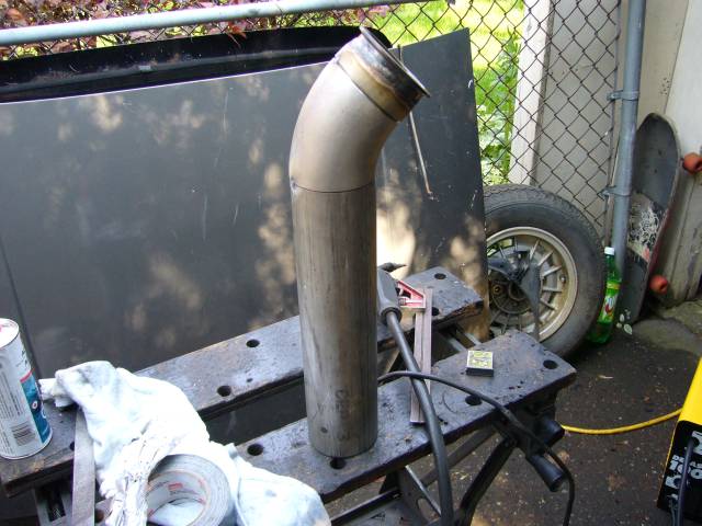
I skipped ahead a little with the pictures as I've covered pipe making before a few times. Here's the downpipe on the bench and ready to weld.
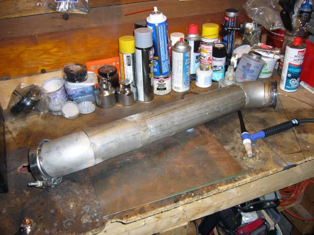
After about half an hour behind the TIG torch, the downpipe was fully welded.
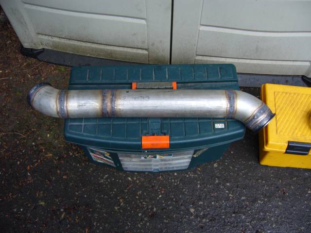
The main reason I made the downpipe out of SCH 10 pipe is because of noise and heat. My ears are a bit sensitive to high pitched noises and on nearly every rotary exhaust I've heard, the pinging and ringing noises drive me crazy. Cars should not sound like marbles in a tin can. Thick pipe makes an enormous difference in the sound you hear from the engine bay which is one reason that OEM downpipes are nearly always thick castings. The thicker pipe also tends to keep heat inside the pipe where it belongs instead of allowing it to easily travel through thin walls. With a little heat wrap, I expect to be able to place my hand on the downpipe while the engine is running. As for weight, this pipe ended up at 11 LBs which is far from "heavy". Quite a bit lighter then the stock precat, but not as light as some aftermarket (though noisy) downpipes. 3" SCH 10 pipe also has a 3.25" inner diameter so I pick up a little flow over tube as well.
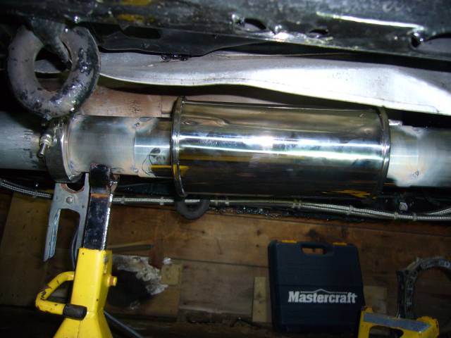
After the welding the downpipe was reinstalled so that the midpipe could be fabricated.
The midpipe is made from 3" stainless tubing. As fun as it was to drive the car around on a virtually open exhaust, it gets tiring quickly. The amusement starts to drain when you set off every car alarm on the street, police officers give you dirty looks, you have to yell at passengers to have a conversation and starting the car gives old men heart attacks in parking lots. To combat the noise I used a Vibrant Performance Ultra-Quiet 3" Straight Through Resonator. These are made of 3" stainless, have a straight through design (no restriction) and are packed with stainless mesh so even the heat of the rotary won't tear them up. Best of all, they work very well and are quite cheap.
Also notice that I've set up the entire exhaust with V-bands instead of flanges. I'm sick of exhaust leaks and V-bands are far easier to remove and reinstall. This will come in handy at the track as I will soon be fabricating a dump pipe that can be swapped onto the downpipe when racing. It's going to dump behind the passenger tire.
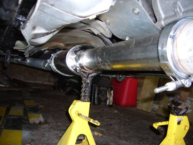
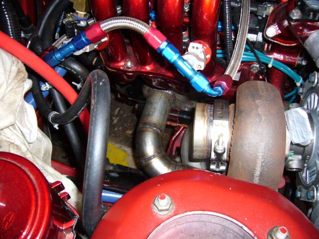
Here's a closeup of the resonator tacked into place. I put it far back from the super hot gasses at the end of the downpipe, and placed it so that it's within the factory heat shield for the stock cat. Also notice the V-band on the catback. I'm kind of disappointed with the ATP Turbo V-Band set. It's not that they are bad parts, but they could be better if they were made with stainless or had an inner lip like the Vibrant V-Bands. Also they were easily 1/16" loose on the 3" tubing I used, which made it a pain to keep lined up when welding. Other then that, they will certainly do the job.
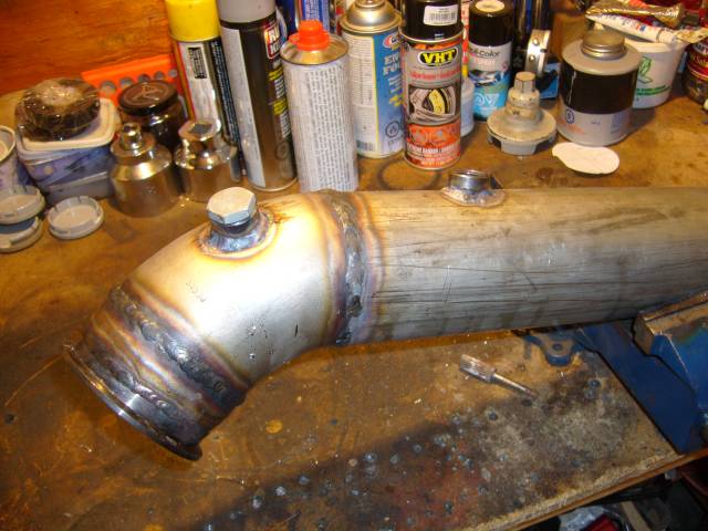
At that point I also installed the bungs for the O2 sensors into the downpipe. The bung closest to the turbo is for the narrowband sensor (it needs to be kept warm) while the bung farther down is for the wideband sensor (it has it's own heater). The plug is in place to prevent damage to the threads during welding.
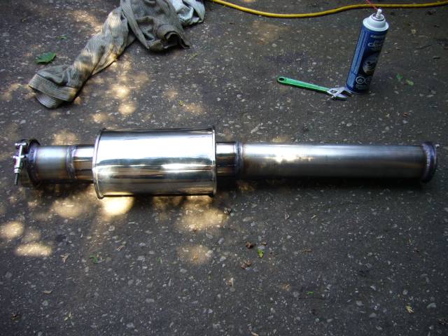
The midpipe and resonator were then fully welded. To keep the V-band flanges from warping, I kept the heat very low (around 50A) and installed a spare flange during welding. Seems to do the trick.
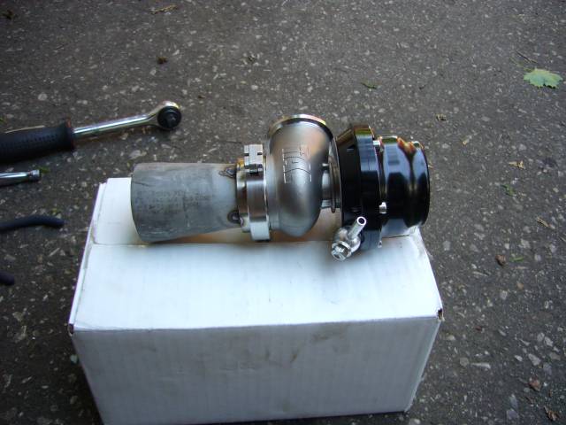
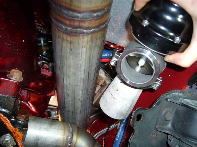
Now that the downpipe and midpipe were complete I knew where the wastegate could sit. The NA lower intake sticks out farther then the TII lower intake, and dictates that the wastegate must go near the frame rail while the downpipe needs to be nearer to the intake. Thus I waited until the downpipe was in place so I could get proper wastegate placement without any interference. The first step was to weld a 2" to 1.5" SCH 10 conical reducer to match the 2" manifold runners to the 1.5" wastegate flange on the Tial 44MM wastegate. Here it is tacked in place.
The position of the wastegate is determined primarily by fitting it in the available space while allowing the best flow from the manifold runners. I really had no interest in strange placement like in front of the manifold (requiring a long and complicated dump tube), on top of the frame rail (basically no space) or underneath the manifold (again, no real space). Also it could not interfere with installation of the downpipe or manifold nuts on the engine. Oh, and the wastegate outlet had to be positioned so that it was possible to route it back into the downpipe while accounting for movement during final welding.
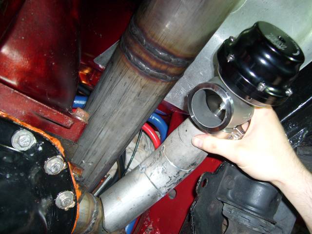
After some test fitting, I ended up with a short section of pipe, leading to a 45 degree el. I found a wicked program online called Tubemiter that makes tube notching very easy. You enter your tubing or pipe dimensions into the software, tell it the angle at which you want the tube to meet, then it prints out a template. This template gets wrapped around the tube and you then trace your pattern and cut it out with the metal cutting implement of your choice. Very slick and it sure saved a hell of a lot of time on the grinder.
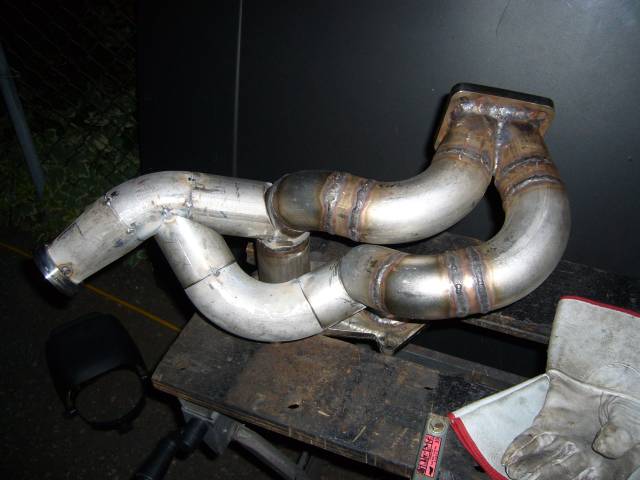
With the first wastegate runner in place, the whole assembly could come off of the car so the 2nd runner could be constructed. I'm not entirely happy with these runners. Ideally wastegate runners should meet the manifold runners are very shallow angles and form a nice Y, not an almost 90 degree T as these do. However the one saving grace with these runners is that they connect to the outside of a bend, so I suspect that gas flow will not be compromised as much as it could be.
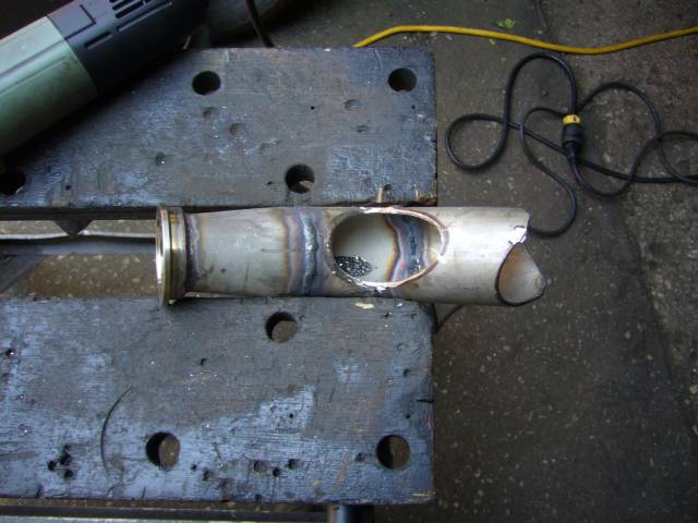
Holes were then cut into the manifold runners to allow the exhaust gasses to actually flow into the wastegate runners. I wonder if anyone has ever been so eager to weld on the runners that they forget this step?
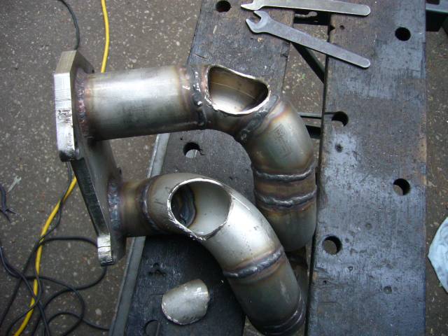
Here's the hole in the rear wastegate runner where the front runner meets it. The two pipes meet at a sharp angle but this passage is huge so I don't expect any flow issues.
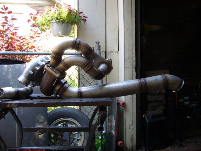
I couldn't resist mocking the whole thing up on the bench.