| Home > RX-7 > My RX-7 > Project Tina > Project Tina, June 5th, 2007: Looming The Wiring Harness, Coolant Recovery Bottle, Wheel painting, Big Turbo Exhaust Manifold Fabrication |
| Home > RX-7 > My RX-7 > Project Tina > Project Tina, June 5th, 2007: Looming The Wiring Harness, Coolant Recovery Bottle, Wheel painting, Big Turbo Exhaust Manifold Fabrication |
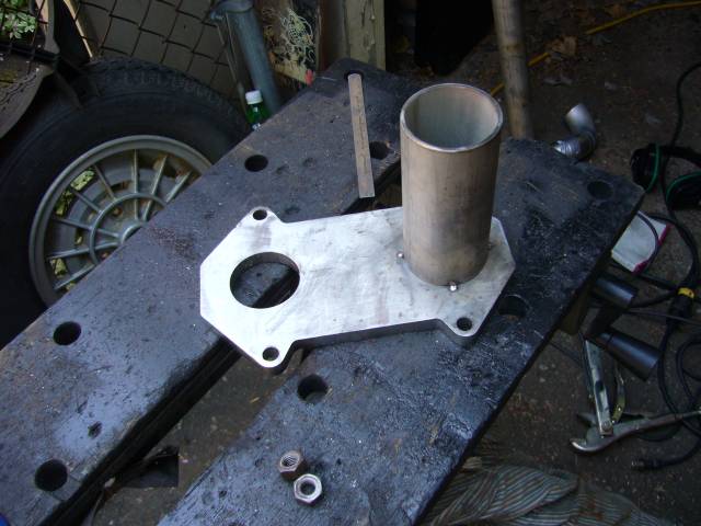
While working on the flange I also repainted the radiator support since it was burned and discoloured from welding in the bungs.
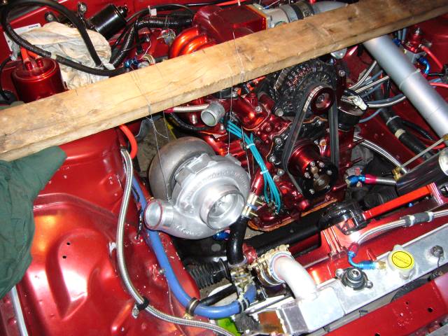
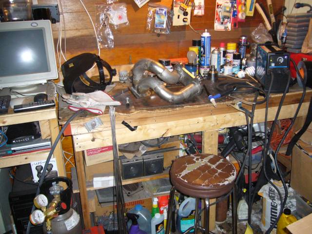
The time honored method of positioning a turbo in an engine bay is to hang it with bailing wire from a 2x4. That way the position can be tweaked without the necessity of holding up a 35 LB object for hours on end. This is not a small turbo, so fitment is a challenge. Either way it's going to be higher then I want and close to the lower intake. It was either position the turbo about an inch higher then I initially wanted, or have to use a lot of short radius (and thus restrictive) els.
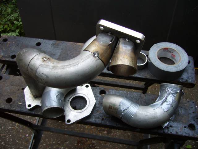
With the turbo position set and the turbine flange bolted on I could start to play with pipe fitment. After holding up various els and short scraps of straight, I had a general idea of what the rear runner was going to look like. It starts with an approximately 5" long section of straight pipe. This pipe would end up being trimmed several times as I discovered that my first mockup did not leave enough space between the manifold and frame rail to allow the flange to slip off the engine studs. Then it follows through two 45 degree else, a short spacer, and then a 90 degree el up to the flange.
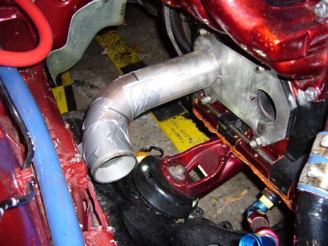
Here's the first duct-tape mockup of the rear runner. As you can see, there is virtually no room between the manifold and fender. I would have to trim some length off the straight section for clearance. When making a manifold like this, buy plenty of 90 degree and 45 degree els. Don't underestimate the usefulness of combining two 45 degree els at different angles. This mockup shows the first 45 degree el pointing to slightly down, while the next one points to the front an a little bit up. A 1" spacer of pipe is then attached to it to move the turbo forward.
Once the position of the els are finalized, the runner gets tacked into place. Generally I bring the runner out of the engine bay and then cut a "window" into the duct tape holding it together inside which I place a tack. This makes sure that the runners don't move around too much, and keeps welding debris out of the engine bay.
A 90 degree el was added to bring the runner up to the turbo.
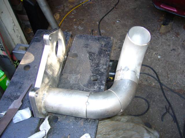
And the flange was tacked into place.
I then reinstalled the manifold onto the engine to test fitment again. In order to maintain clearances the turbo sits with the rear angled a few degrees down (will make it about 10 times easier to fab a downpipe in a cramped area), the front of the compressor angles towards the engine (to provide space for outlet pipe to run past shock tower) and the entire turbo rotates out slightly towards the fender (easier access to oil drain hole).
The front runner is mocked up in the same way as the rear, but this time it can be done outside of the engine bay since the first runner locates the turbine flange. Again, els and spacers were combined until the runner matched up with the engine flange and turbine flange, and did not interfere with the front runner, steering rack or engine mount. I ended up using two 45 degree els, two 90 degree els and two spacers. Almost by accident both runners turned out to be virtually the same length! Yay for me.
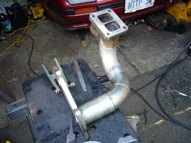
The front runner was then tacked into place...
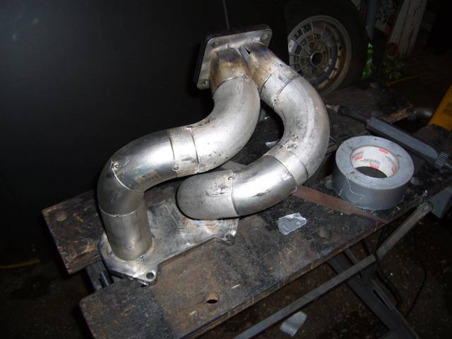
...and the manifold test fitted once again. Still seems to fit.
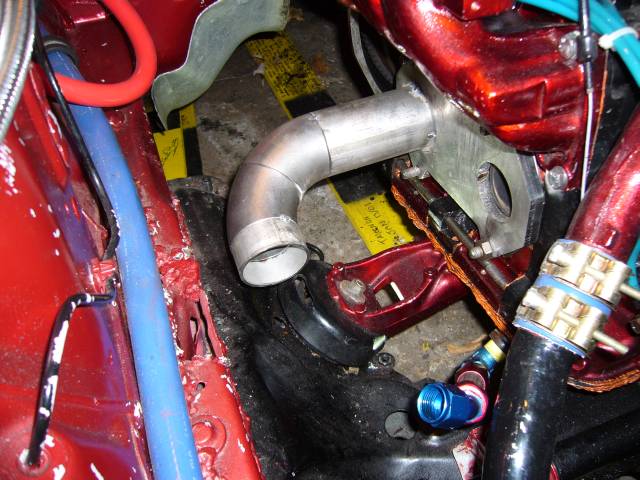
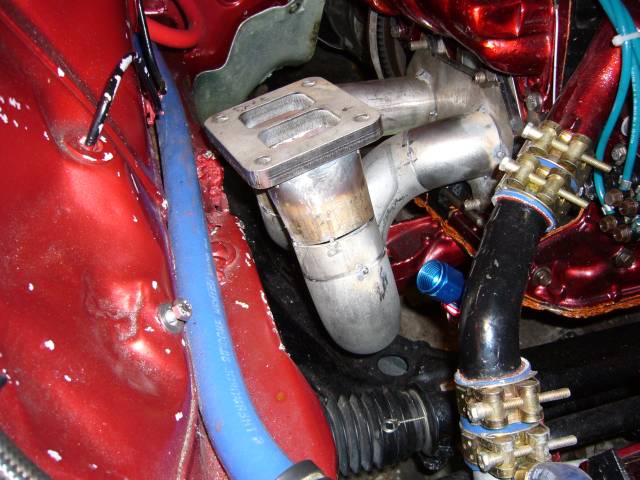
Here's a view of the turbo flange from inside the engine bay. It hovers just over the frame rail. My pipe fitment had a few gaps which is something you ideally want to avoid. Gaps allow the pipe to move during finish welding, and take effort to fill properly.
To do the finish welding I rented a Miller Maxstar 150 STH from the local welding store (Sure Arc Welding Supply). For $200 I got the welder for a month and the gas bottle, consumables (tungsten, gas, filler) extra. Pretty good deal considering that this welder retails for $1500 US, and that doesn't include the gas bottle and regulators. Overall I'm very happy with the unit and if it could do AC (it's DC only) I'd buy it in a second. For a 120V unit it's very capable of doing stick or TIG welding at up to 150A (30% duty cycle) and weighs only 18 LBs. I didn't get the optional foot control but I found that Lift-Arc was very easy to use after about a 2 minute learning curve.
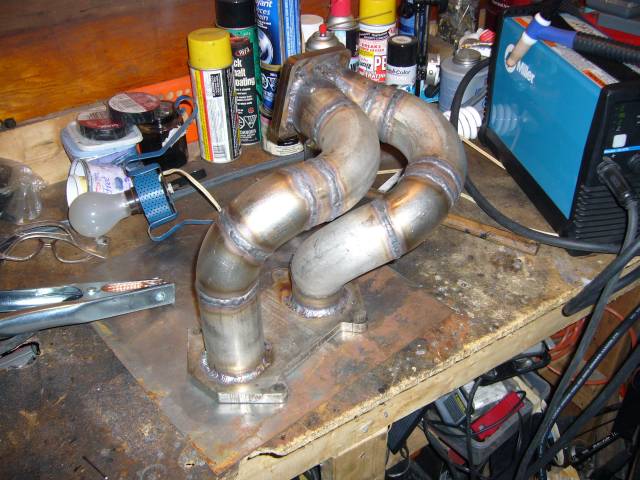
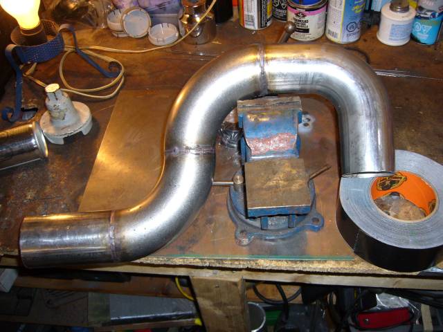
After a few hours of welding, here's the finished result. Most of the pipe was welded at 105A with great penetration and puddle control. To do the fillet welds at the flanges I cranked it up to 130A. The valley between the runners at the turbo flange was welded with some frustration by extending the tungsten about 3/4" out of the gas cup and cranking the gas flow to about 35CFH. I welded about as much as I could on each runner, then cut the tacks and welded each runner off the manifold separately. After a little frustration getting everything lined up again, the runners were tacked back into place and then fully welded.
Overall I'm happy with the manifold so far. Still need to do the wastegate runners but I can't get those installed until the downpipe is in place. This was actually a lot harder then making my intake manifold as the intake consisted of basically all 90 degree angles. The exhaust manifold has many more compound curves which can be a bit of a trick.
If I had been thinking I would have bolted both the engine flange and turbo flange to another thick piece of metal to minimize warping. Both flanges warped about 1MM during welding (no matter what you do, stainless steel loves to move during welding) so I'll have to send it to the machine shop to be flattened.
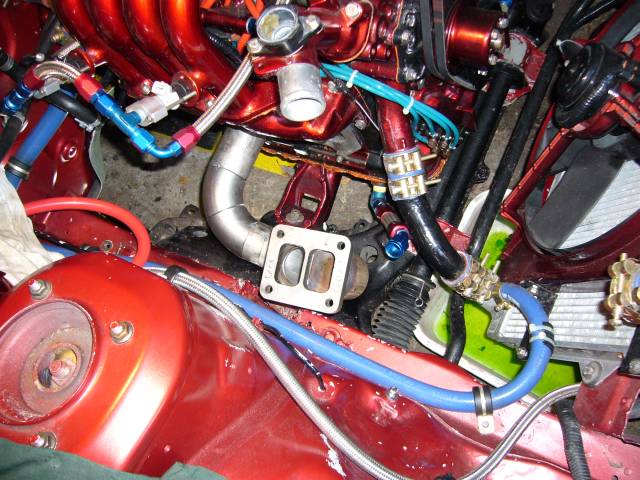
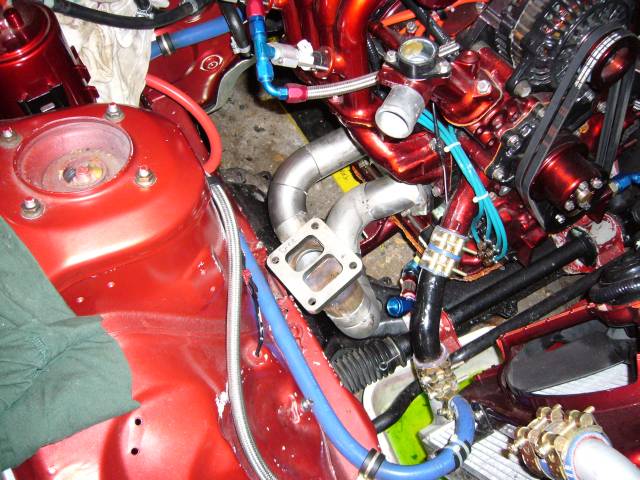
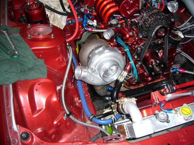
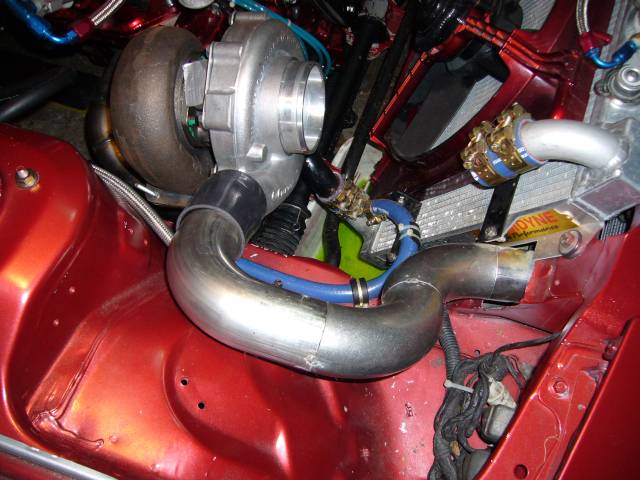
Finally the manifold can support the weight of the turbo by itself so it's time to place it in the engine bay. Beastly...There's enough room between the turbo and lower intake for plenty of heat shielding, and the oil drain will be easy to run. Going to take some thought on where to route a TID though.
With the turbo in place I could start to deal with the plumbing around it. First task was to make a new outlet pipe. From the intercooler I used a short piece of 2.5" stainless tube, then two 90 degree weld els, then a 90 degree mandrel bend I purchased from ATP Turbo. I would have preferred to use another weld el but I ran out and figured I'd just get some 90 degree mandrel bends from ATP at the same time I was ordering some other stuff. I kind of wish that I had stuck with the els because the mandrel bend is not consistent throughout. The tubing around the bend is slightly oval in shape which took some shaping to make it fit the perfectly round els. The camera angle is looking down at the top of the rad, which is why all the angles look funny.
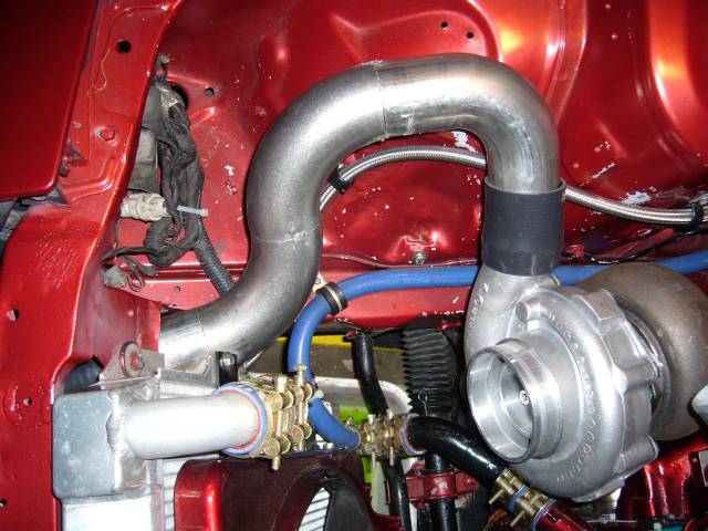
Here's another view of the turbo outlet pipe showing how it hugs the inner wheel well. I'm going to add a bung in this tube to provide a boost signal to the wastegate.
The pipe was then fully welded. I set the TIG to pulse, put the current around 50A and fusion welded most of it. Filler was required in a few areas where the weld wanted to sink too much. You can see a few dirty areas also caused by the flux core wire I used to tack. The only annoyance is that the flux and contamination in the tack cause the TIG arc to go funky as it passes over. This produces a lot of hissing and popping as the contamination burns. Cleaning with acetone helps a little but flux core welds in general are dirty.
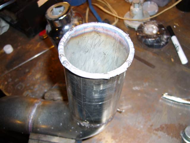
You can't see it very well in this picture as the flash kind of blew the image out but these are the beads on the end of the tube to prevent the couplers from blowing off. To create them I decided to be a total show-off so I tacked on a piece of 3/32" welding wire, used the torch to bend it around the circumference of the tube, and then welded it in place using a 1/16" filler. Needed a sharp tungsten with the welder set to about 30A. For my next trick, I'll weld the sharp edge of a razor blade to a railroad track.
And that's basically where things are now. Since I wrote this I've welded the v-band couplers onto the cat-back and made a new downpipe (with resonator). All that remains is to set up the wastegate runners and valve, figure out a TID, run oil and water to the turbo, modify the upper coolant pipe and throw on a new set of tires. Then it's back on the road for the summer, some tuning, and the interior when I feel like it.