| Home > RX-7 > My RX-7 > Project Tina > Project Tina, September 20th, 2006: Gauges, Intercooler and Piping, Final Assembly and Startup |
| Home > RX-7 > My RX-7 > Project Tina > Project Tina, September 20th, 2006: Gauges, Intercooler and Piping, Final Assembly and Startup |
To mount the top of the cooler I just made two "L" shaped brackets out of 3MM thick steel. Holes were drilled into the radiator crossmember to secure them with bolts.
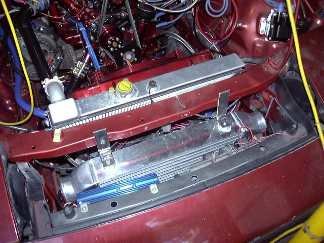
The bottom of the cooler was supported with another set of brackets made from the same steel as the top and a little angle iron. Here they are just tacked. The car-side of the brackets attach to two M8 nuts that are already on the frame rail between it and the bumper. I'm not sure what Mazda intended them for, but there are two on each side which are prefect for intercooler brackets. The intercooler mounted just a little higher then normal because I have a habit of bumping things with the bottom of the bumper and I would hate to mess up the intercooler.

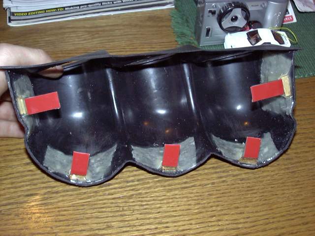
To fully adhere the mounting brackets to the gauge pod, I mixed up a batch of epoxy and used it to soak a cloth mesh. This made a sort of "fiberglass" which then was laid over the brackets and onto the gauge pod. The space between the brackets and pod was then filled with wood and epoxy. Once dried, this became super strong. In fact I could bend the entire dash up by pulling on the pod once the 3M tape had set.
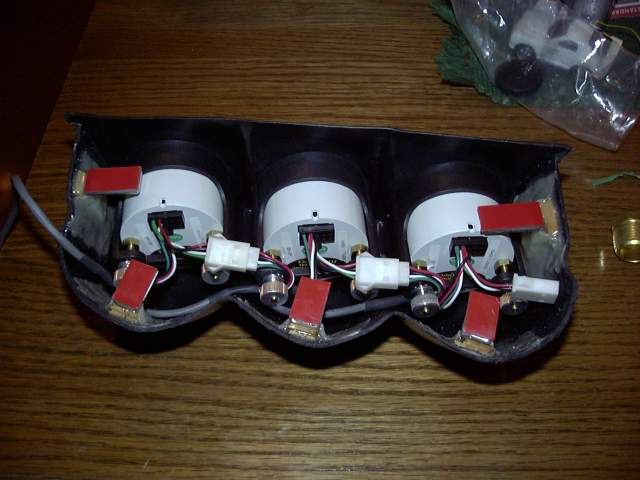
Once the epoxy was dry I installed and fine tuned the position of the gauges. From left to right we have oil pressure, oil temperature and fuel pressure.
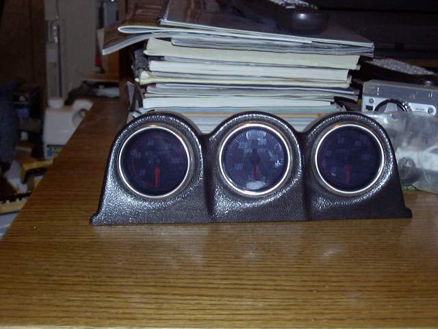
As I mentioned, one of the advantages of the Nexus gauges is the wiring harness. Each gauge plugs into the bus, which then leads back to the central control box. In this way the mess of wiring and tubing that normally leads to a gauge pod is avoided. There are no messy and dangerous fluid leaks into the cabin, and the gauges are totally isolated from any badness that occurs in the engine bay.
The gauge pod is still going to need a little bit of work to make it fit the dash perfectly. A litle bit of felt around the edges will probably clean up the pod and make it look close to factory.
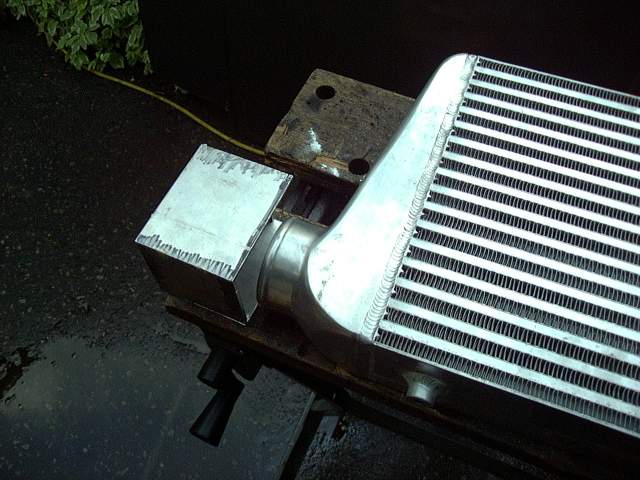
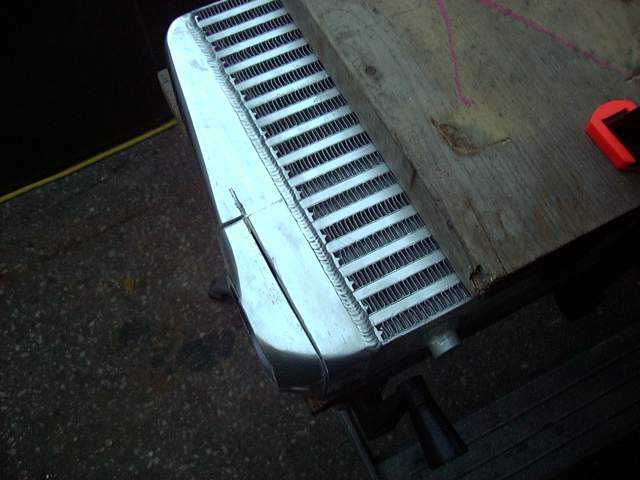
Back to the intercooler. The stock inlets and outlets run in the wrong direction for how I wanted to mount the cooler so I needed to modify the end tanks. The inlet needed to go into the passenger side tank at about a 90 degree angle, and the outlet needed to exit the drivers tank at about 45 degrees.
The solution was to build two small tank extensions out of aluminum and replace the existing inlets and outlets. I cut the tank sections then tacked them together.
Time to ruin a perfectly good intercooler! Out came the cutting wheel and safety glasses. A few minutes of work with the angle grinder and the deed was done.
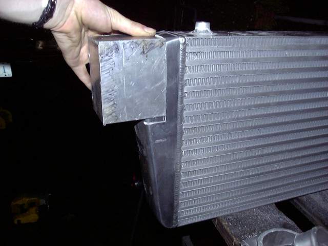
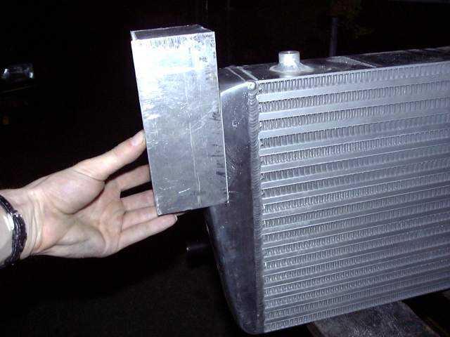
The tank extension fit fine though some filing would be necessary before it was welded in place.
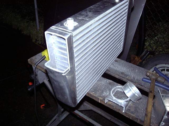
The drivers side was cut in the same way, but a little larger to allow for fitting of the angled outlet pipe.
The drivers side tank extension looks a little weird but the extra height was necessary as there was no way to predict where the pipe would end up until the intercooler was modified and mounted in place.
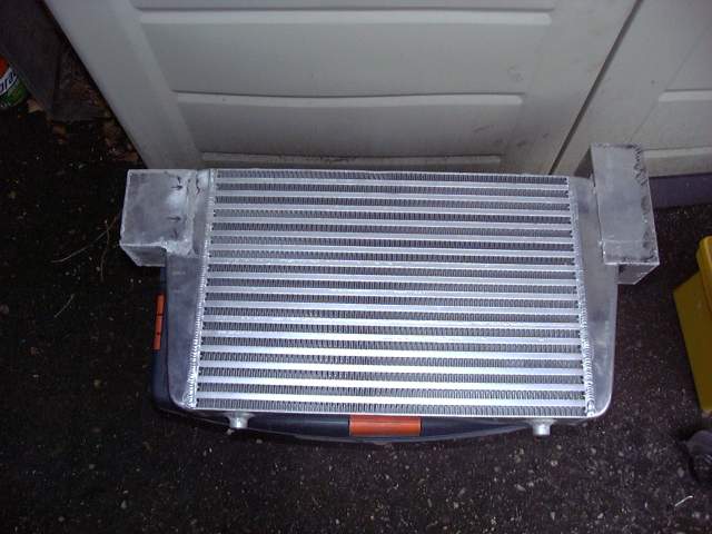
The tanks were then tacked together so the cooler could be fitted to the car.
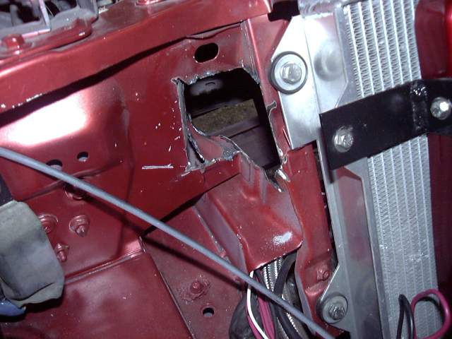
Once the cooler was in place I could cut a hole in the drivers side radiator support for the intercooler piping. There's actually quite a lot of space available here if you are willing to go through on an angle so 2.5" piping easily fits. I found that the angle grinder was not a very good tool for this after cutting myself pretty badly several times. Oddly enough the Dremel tool with cutting disks was quicker. While it cut slower, it was far easier to maneuver around and not nearly as scary. The hole is a little rough right now but during the winter I'll finish it off and trim the edges with rubber.
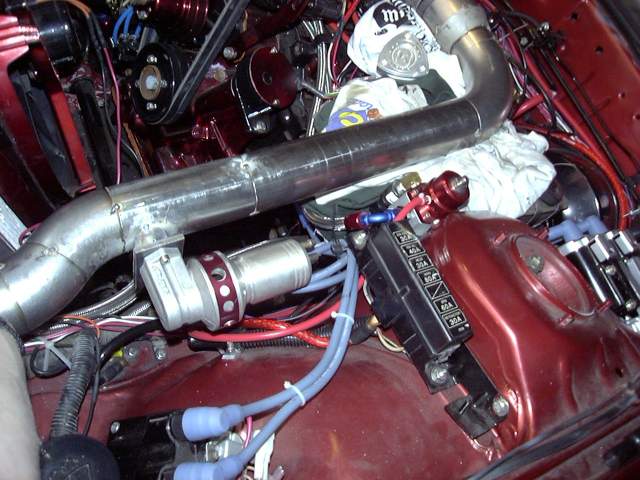
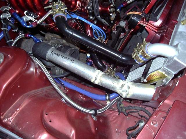
Because the stock turbo is just temporary (I'm just using it for the break in to avoid having to fab a new manifold and allow me to drive the car) I didn't waste much time on the piping. This thing took all of about half an hour and was made from scrap tubing. I used a little 2" exhaust tubing, some 2" stainless tubing and some spare 2.5" galvanized tubing that I had lying around. This, my friends, is ghetto. But it will do the job until I upgrade the turbo. A little silver paint will clean it up. You can also see that the heater hose has been secured with clamps and the temporary intercooler pipe leaves plenty of room for the TID.
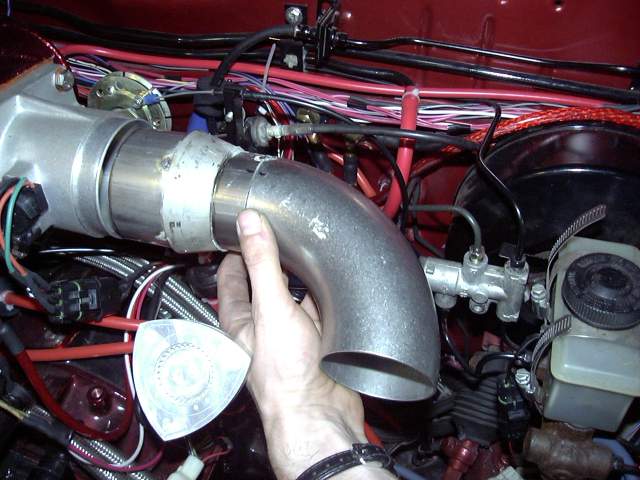
Now I could start the drivers side piping. The outside diameter of the throttle body is about 3.25" so I needed to start with a small section of 3" stainless tube to provide a clamping surface for the silicone coupler. From there, a 3" to 2.5" thick SCH 10 stainless transition connects to a sort section of 2.5" stainless tube, then a 90 degree stainless el. I used a thick SCH 10 transition so that I had enough thickness to drill and tap for 1/8" NPT to install as set of nipples for fresh air connections to the injector air bleeds, metering oil nozzles and purge valve. Everything is just being tacked for now for final welding later. To connect the pipe to the throttle body, I purchased a 3" to 3.25" silicone transition coupler.
A weld el was cut to 3 random angles and recombined to form a curve that leads from the intercooler outlet pipe and up to the el coming from the throttle body. The long pipe between was done in two sections to provide a very slight (one or two degrees) bend for final alignment.

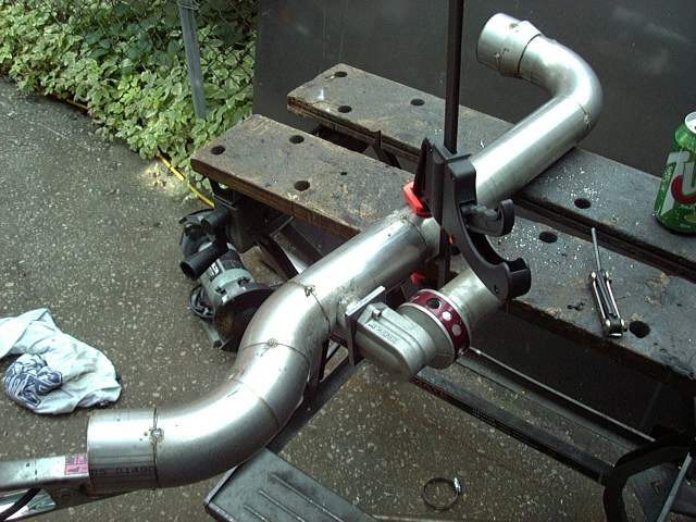
Here's the finished pipe tacked together.
A 1" hole saw cut through the stainless to make a mounting area for the BOV. Using a short section of 1" tubing I tacked on the flange while keeping the BOV level. I would have much preferred to mount the BOV closer to the throttle body but there was simply not enough space available to do so.
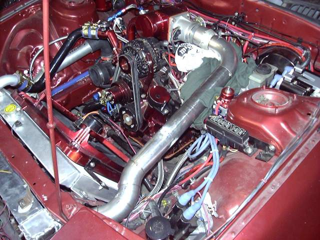
The pipe was then laid into the engine bay to check the final fit before it finish welded.