| Author |
 Topic Topic  |
|
machinist18
New Member
USA
2 Posts |
 Posted - Oct 20 2007 : 12:23:23 AM Posted - Oct 20 2007 : 12:23:23 AM


|
| I would like to build the Ringing Phone Light Flasher but I don't understand what the two 5v. inputs are and where they come from. Could someond help please. Thanks, John |
John F Carter |
|
|
audioguru
Nobel Prize Winner

Canada
4218 Posts |
Posted - Oct 20 2007 : 10:36:42 AM
|
| The circuit needs a 5VDC power supply. |
 |
|
|
machinist18
New Member
USA
2 Posts |
Posted - Oct 22 2007 : 03:32:21 AM
|
| Thanks, John |
John F Carter |
|
|
|
konduri
Apprentece

17 Posts |
Posted - Oct 25 2007 : 2:25:44 PM
|
| wat is the need for connecting transistor before the relay ckt?why cant the output of opto isolator be directly given to relay in this light flasher ckt with a telephone ring? |
|
|
|
audioguru
Nobel Prize Winner
Canada
4218 Posts |
Posted - Oct 25 2007 : 5:40:46 PM
|
quote:
Originally posted by konduri
wHat is the need for connecting a transistor before the relay ckt? why cant the output of the opto isolator be directly given to relay in this light flasher ckt with a telephone ring?
Why don't you look at the datasheet for the 4N27 opto-isolator??
The phone line gives a current of about 5mA to the LED in the isolator then its transistor will have a minimum of only 0.25mA output current.
How much current does the relay need? 40mA?
The transistor amplifies the 0.25mA then has an output current that is high enough to drive a relay. |
|
|
|
konduri
Apprentece
17 Posts |
Posted - Oct 26 2007 : 08:43:39 AM
|
oh..thank u sir ...Sir,i have many more doubts concerned with this ckt.Actually,this circuit is one of the parts which we are goin to implement in our project at B.Tech.So,i earnestly request u to patiently reply to my queries.What i understood is tat optocoupler is meant for elecrtical isolation.Is there any other reason besides this? ...Sir,i have many more doubts concerned with this ckt.Actually,this circuit is one of the parts which we are goin to implement in our project at B.Tech.So,i earnestly request u to patiently reply to my queries.What i understood is tat optocoupler is meant for elecrtical isolation.Is there any other reason besides this?
One more thing is tat wat should be done with pins 3 and 6 of optocoupler 4N27.Should they b left open..I have no where found the pin description for 4N27. |
|
|
|
audioguru
Nobel Prize Winner
Canada
4218 Posts |
Posted - Oct 26 2007 : 11:11:13 AM
|
The telephone lines are perfectly balanced and are not shielded. Both wires pickup the same amount of hum radiated from electricity wiring but the perfect balance at each end cancels the hum. If you don't isolate the circuit from the telephone line then the circuit will couple one telephone wire to ground and leave the other wire as an antenna for picking up and transmitting hum.
The datasheet for most active electronic parts can be found at many datasheets sites. I go to www.datasheetarchive.com . You can select the datasheet from any manufacturer. I usally use Fairchild's datasheets. |
|
|
|
konduri
Apprentece
17 Posts |
Posted - Oct 26 2007 : 11:28:49 AM
|
| One more thing sir..if we attempt 2 measure the voltage across optocoupler at pin 5,wat can be the expected voltage when the ring comes...Im askin u this question because in our project we are looking forward to give the optocoupler o/p as i/p to a PIC microcontroller...IS tat feasible in ur view...And also let me know whether the o/p of optocoupler is an ac signal or dc signal here... |
|
|
|
sergiosparks
Apprentice

Philippines
132 Posts |
Posted - Oct 26 2007 : 11:33:47 AM

|
| Here's a simple flasher that i made a 10K resistor in series with an LED across the the telephone line if a call is coming it blinks if an extention is in use it dims.After doing that then you can improve it using opto couplers or some advanced alarm.If it does not light reverse the connection. |
|
|
|
audioguru
Nobel Prize Winner
Canada
4218 Posts |
Posted - Oct 26 2007 : 2:01:43 PM
|
quote:
Originally posted by konduri
One more thing sir..if we attempt 2 measure the voltage across optocoupler at pin 5,wat can be the expected voltage when the ring comes?
What do you think it does? What do you think the telephone line does when it rings?
I don't know your country's phone system but in North America ringing is 20Hz at 90VAC. So the LED in the isolator will blink at 20Hz and cause the photo-transistor to conduct and turn off at 20Hz. Our ringing has the cadence of 2 seconds on followed by 4 seconds off. Yours might be ring, ring then a pause.
quote:
Im askin u this question because in our project we are looking forward to give the optocoupler o/p as i/p to a PIC microcontroller...IS that feasible in ur view?
If the photo-transistor uses the same 5V power supply as the microcontroller then its pulses are fine as an input.
Maybe you should filter out the 20Hz pulses so the signal is a steady high or low during ringing.
Look in Google for Ringing Detector Circuit.
I found a good filter here:
http://www.avagotech.co.jp/assets/downloadDocument.do?id=1607 |
|
|
|
konduri
Apprentece
17 Posts |
Posted - Oct 27 2007 : 03:18:05 AM
|
wat abt the relay sir which we have used in the circuit here...Its simply mentioned as solid state relay...Does it have any specifications...
If i want to use the above circuit for simple applications such as glowing an LED upon the telephone ring,the 220 V Ac suppply can be replaced by a 5V DC supply na...Please let me konw whether im right or not... |
Edited by - konduri on Oct 27 2007 03:26:44 AM |
|
|
|
Aaron Cake
Administrator

Canada
6718 Posts |
Posted - Oct 27 2007 : 11:08:15 AM


|
The solid state relay needs to have a "coil" voltage to match the circuit's supply voltage, and "contacts" to match the load you are trying to switch.
A regular relay works fine but buzzes as it works and will wear out quickly. Putting a low value capacitor in parallel with the contacts will help with the wear greatly but you'll still get the relay clacking when the circuit flashes... |
|
|
|
audioguru
Nobel Prize Winner
Canada
4218 Posts |
Posted - Oct 27 2007 : 11:44:01 AM
|
quote:
Originally posted by konduri
If i want to use the above circuit for simple applications such as glowing an LED upon the telephone ring,the 220 V Ac suppply can be replaced by a 5V DC supply na...Please let me konw whether im right or not...
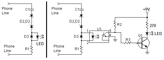
1) Replace the LED in the opto-isolator with an ordinary LED then a power supply and relay are not required.
2) Replace the relay with an ordinary LED in series with a current-limiting resistor. Use a 9V battery then a power supply is not needed.
Download Attachment:  LED lights when phone rings.PNG LED lights when phone rings.PNG
8.13 KB
 |
|
|
|
konduri
Apprentece
17 Posts |
Posted - Oct 27 2007 : 12:16:42 PM
|
| Its really wonderful sir..but one clarification...In the circuit involving relay,u stated tat the purpose behind using the transistor Q1 is tat it acts as amplifier to generate necessary signal to drive the relay..But here,wat is the role played by the amplifier...Please let me know the purpose of using amplifier here... |
|
|
|
konduri
Apprentece
17 Posts |
Posted - Oct 27 2007 : 12:21:23 PM
|
| Also please let me know ur reasoning behind using 9V DC power supply for biasing purpose instead of 5V used earlier... |
|
|
|
audioguru
Nobel Prize Winner
Canada
4218 Posts |
Posted - Oct 27 2007 : 6:48:58 PM
|
quote:
Originally posted by konduri
In the circuit involving relay,u stated tat the purpose behind using the transistor Q1 is tat it acts as amplifier to generate necessary signal to drive the relay..But here,wat is the role played by the amplifier/
Look at the datasheet for the 4N27 opto-isolator. I said earlier that with a 5mA input to its LED then its output current could be only 0.5mA which is too low for an LED to be seen. The transistor has current gain so that the added LED will be bright.
quote:
please let me know ur reasoning behind using 9V DC power supply for biasing purpose instead of 5V used earlier
I said to use a 9V battery to power the LED instead of a 5V power supply. You can use a power supply if the phone will be ringing all the time which will drain a 9V battery in one day. |
|
|
|
Topic |
|