| Home > RX-7 > My RX-7 > Project Tina > Project Tina, May 26, 2005: Oil Pan, Porting Turbo Wastegate, Rust Repair, Misc. Wiring |
| Home > RX-7 > My RX-7 > Project Tina > Project Tina, May 26, 2005: Oil Pan, Porting Turbo Wastegate, Rust Repair, Misc. Wiring |
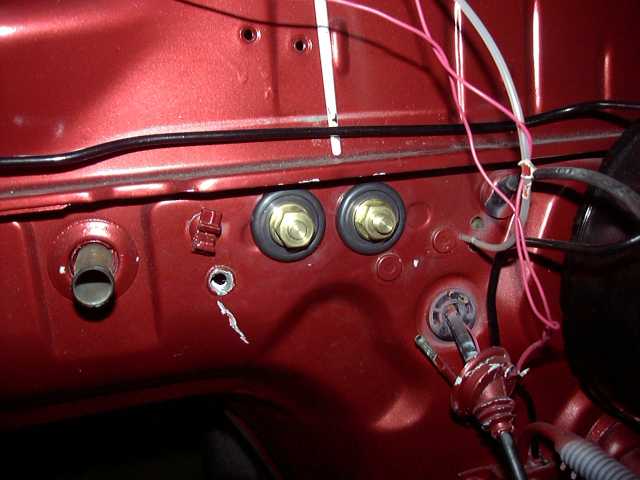
One of the things that really bothers me when people do electrical work is sloppiness. There is absolutely no excuse for bringing cables through unprotected firewall connections. These are battery bulkhead connectors. They provide a pass through that is safe, clean and sanitary. The solid brass bolt in the middle is insulated by a plastic insulator, which screws into the hole and is secured on the other side with a nut. A stud on each end is then provided to make the electrical connection. Not only is this a highly safe and reliable way to pass thick cables through bulkheads, but it also provides a distribution point in the engine bay. From the ground, I can run a thick ground to the engine and the front of the body. From the +12V, a thick wire can go to the starter directly, and then another to the fuse box (and from there, ignition, e-fan, etc.). In this case, the alternator becomes part of the engine harness, which then connects to the battery which is now located inside the car. The disadvantage of these passthroughs is that they are a nightmare to install if the dash is in place. You can see how I had to drill out a stud from the engine side that served to hold the stock dash wiring harness in place. This was done for clearance. The stud has since been welded back into place.
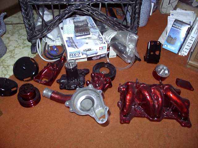
Back inside, here are the finished engine accessories. Intake manifold, water pump and housing, mounts, EGR blockoff, etc.
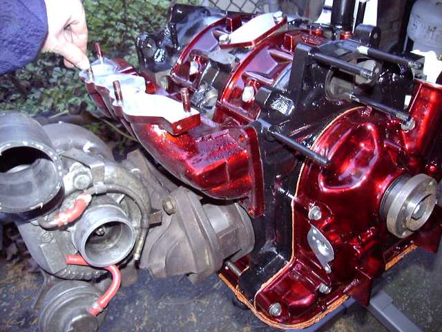
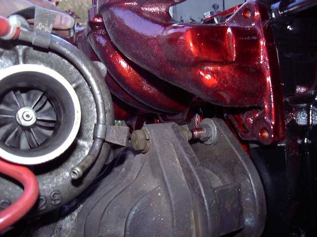
With the engine outside, some mockup was done to make sure everything still fit. These next few pictures provide a great view of the manifold on it's spacer, and how little clearance there actually is between the turbo and lower intake.
![]()
![]()
![]()
![]()
Some great shots of the turbo and lower intake.
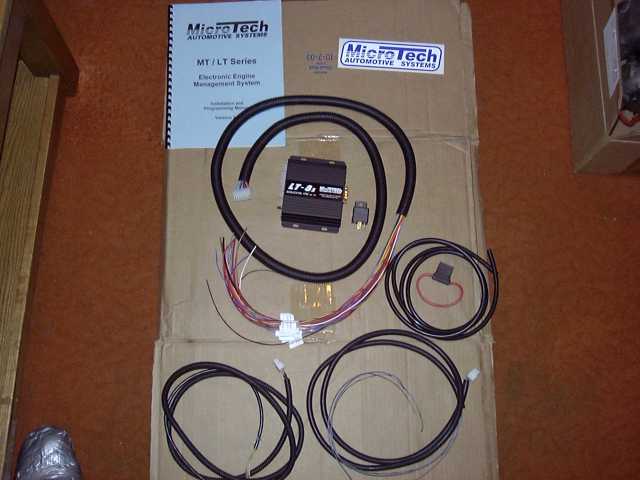
About this time, the Microtech LT-8s arrived in the mail. Shown in the picture is the wiring harness, ECU, vacuum line, relay, instructions and of course the ever important sticker.
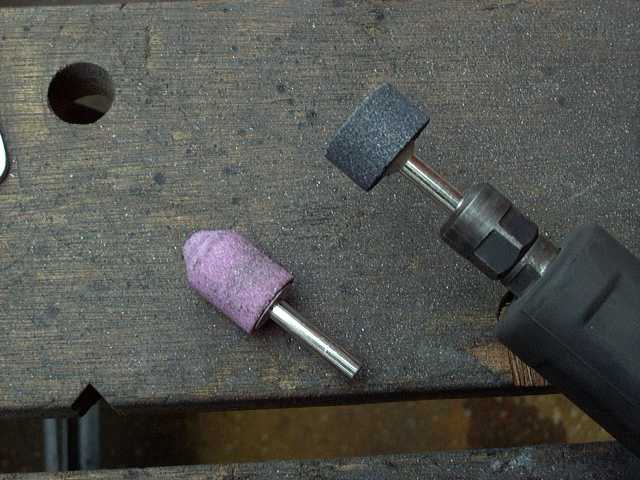
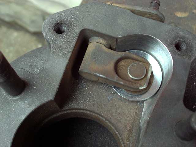
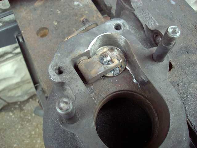
Time for a little more wastegate porting. Some of you might recognize these pictures. :) Here are the stones I used.
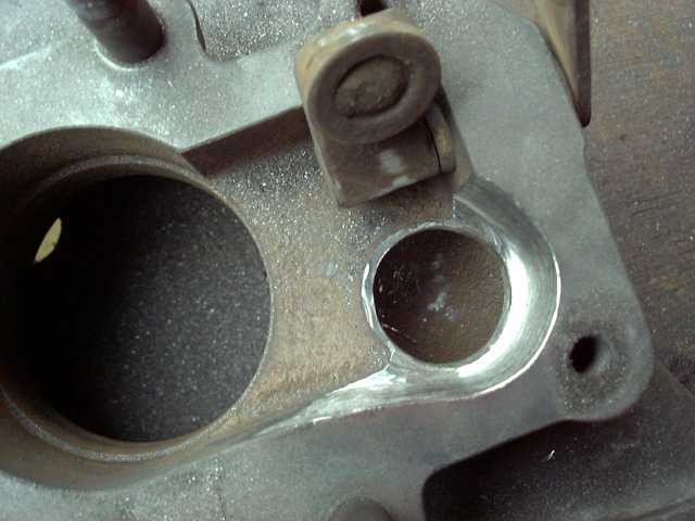
Widening the orifice...
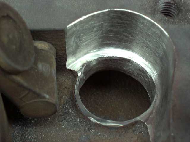
Here's a good shot of the new wastegate passage. It's about twice as large as stock.
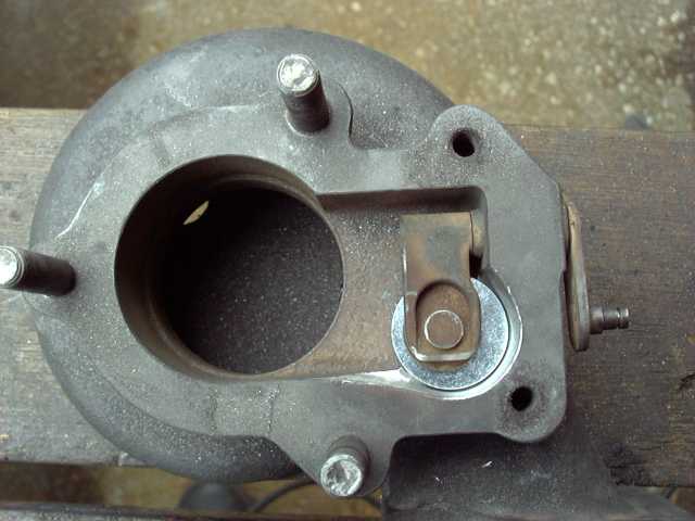
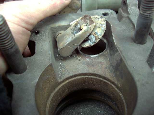
Test fitting the new flapper door.
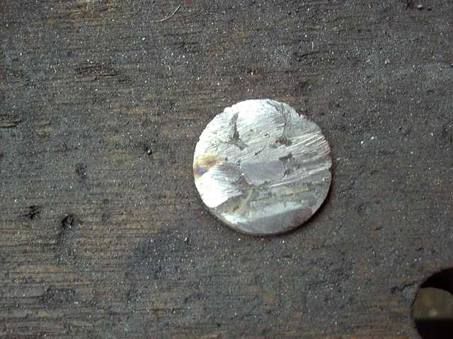
Here's the new flapper door. Two flat washers were simply welded together. The welds were then ground down, and the two washers became as one.
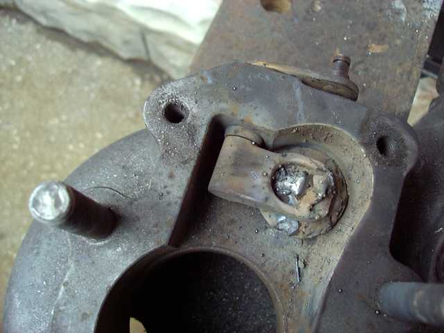
Some shots of the new flapper welded in place.
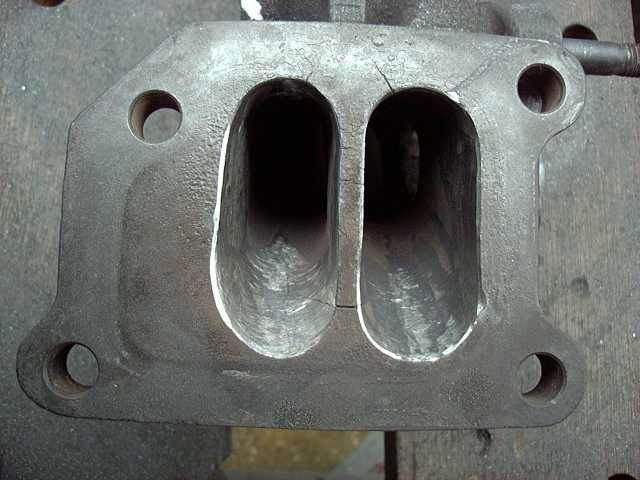
While I'm at it, I figured I would finish porting the exhaust runners. These are not massively ported, since if you make the center divider too thin, it will easily crack (more then it already has).
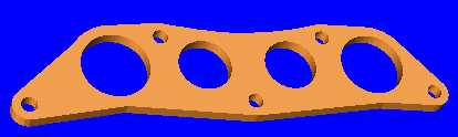
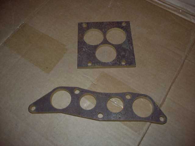
Since I am making a new upper intake for this engine, I needed some flanges cut. I decided to have them done by a machine shop to save some time. So all that was necessary was to design the flange in CAD, and send it to the shop. They cut it out of 8MM steel with a water jet machine. I had a bunch done, so I can experiment with different intakes.
More work on that damn oil pan. I've never been happy with my original turbo drain solution (3/8" 90 degree plumbing elbow). There's nothing fundamentally wrong with it, but there are more elegant ways of accomplishing the task. So I decided to remove the oil drain, and weld on a straight 1/2" NPT pipe union. This would provide a perfect location, that was not in the way of the engine mount like the old drain.
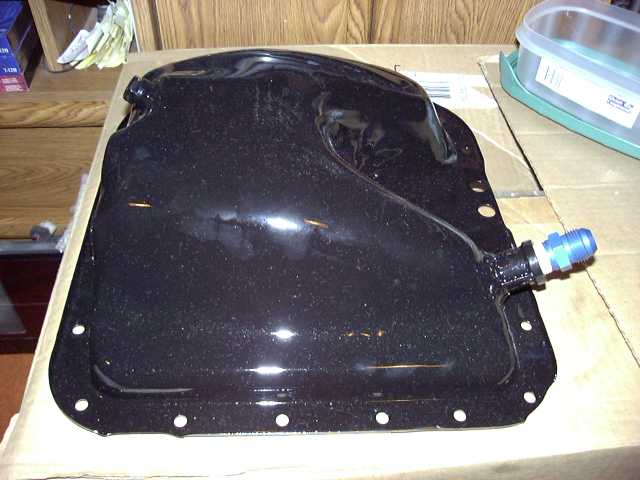
Sometimes, the best laid plans of mice and men just don't work out. I purchased a fancy billet aluminum T4 style oil drain flange from ATP Turbo with the intention of going all braided stainless/AN from the turbo to the pan. Unfortunately, it didn't fit. The flange met up with the holes correctly, but the stock turbo simply doesn't provide enough space between the center section and exhaust flange for any kind of fancy fitting. So I am stuck with the stock drain until I upgrade the turbo. Knowing this, I still wanted the setup to be as reliable and leak proof as possible (I had multiple failures with my old rubber hose). Once again hitting the plumbing isle at Home Depot, I found a 1/2" NPT copper sweat threaded fitting. This was brazed into the cut-off end of the stock drain tube.
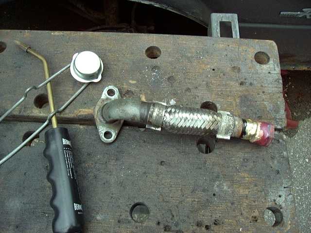
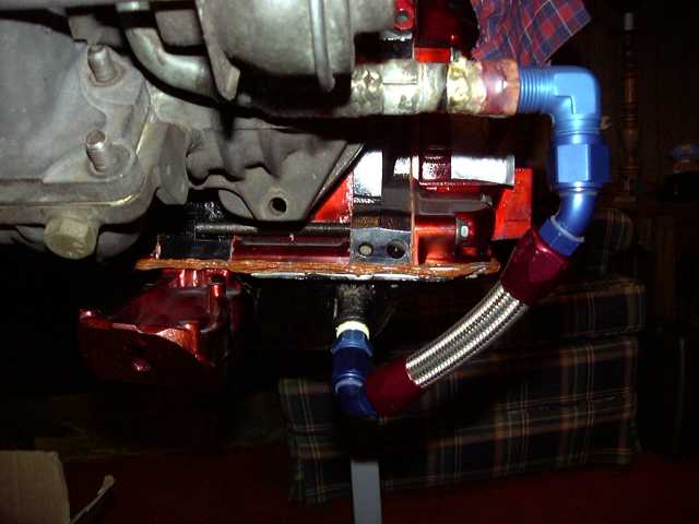
From the brazed fitting, a 1/2" NPT to -10 AN 90 degree fitting was used, and the rest was plumbed in -10 AN and braided stainless. This will never leak. When I upgrade the turbo, the line will be remade to match the new (much more spacious) center section.
Finally, here are the flanges back from the machine shop. The water jet did an excellent job. I also had some throttle body flanges cut for the stock throttle body, even though I won't be using it.
So there you have it. This pretty much brings us up to this weekend. If the weather holds out, the final assembly of the engine (turbo, manifolds, water pump, MOP, flywheel, clutch, etc.) will take place and it will actually be installed in the car. This is a huge milestone, since it means that now I have the location of everything, so fabrication of the upper intake can start, as well as all the wiring, plumbing, etc. I expect things to progress quickly in the engine bay at this point. Now, I can turn my thinking powers to the interior. The seats are heading out to upholstery, and I'm going to tackle the headliner myself. Soon, new carpets will be ordered...