| Home > RX-7 > Tech/Mods > Modifications > Turbo NA Guide > S-AFC Install, Turbo Inlet Duct, Downpipe Adapter |
| Home > RX-7 > Tech/Mods > Modifications > Turbo NA Guide > S-AFC Install, Turbo Inlet Duct, Downpipe Adapter |
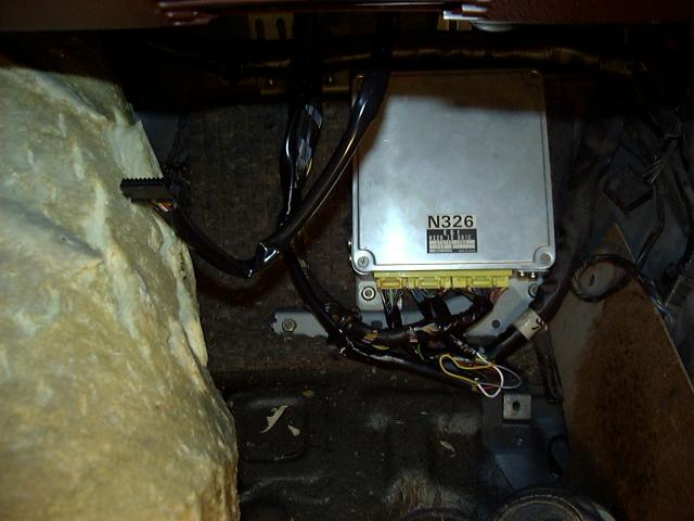
As a break from working on the engine, I went inside the car to install the S-AFC. Here you see the wiring harness being wired into the car's stock ECU harness. Space was a little cramped since I couldn't open the passenger door, so I decided to solder instead of using the crimp connectors that came with the S-AFC.

The wiring was then run under the dash and up to the center console where the S-AFC was secured to the ash tray lid with double-sided tape. I have no use for the ash tray, so it seemed like a logical spot for mounting. Yes, that's my right knee in the picture.
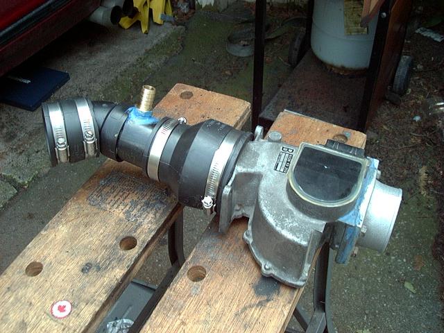
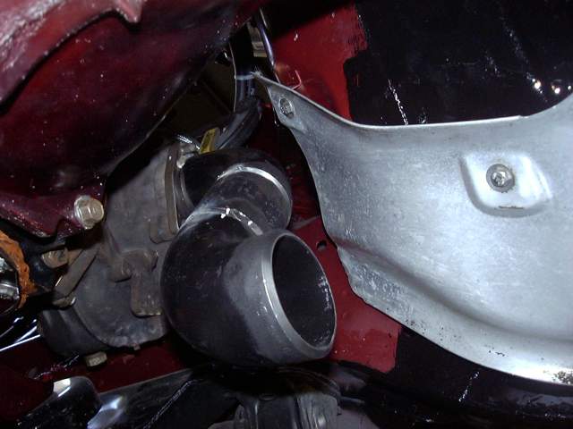
With the S-AFC installed, attention was turned to getting air into the turbo. There was no hope of fitting either an stock NA or TII TID (Turbo Inlet Duct), so a custom duct was made out of ABS pipe. It basically consists of a 2.5" rubbler coupler, connected to a 45 degree elbow, connected to a short section of 2.5" pipe, and finally attached to the AFM using a 2.5" to 3" flexible coupling. With a little wiggling and bending of the flexible couplers, this TID just barely fit. The brass nipple shown in the photograph connects to the air hose for the BAC (Bypass Air Control) valve. This is necessary to allow the stock ECU to adjust the idle.
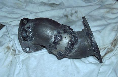
A downpipe adapter was constructed to connect the turbo to the rest of the exhaust system. As you can see from the picture, there is nothing commercially available that would have worked, and a regular TII downpipe would not fit due to interference from the firewall. This downpipe adapter is made from a 90 degree 2.5" steel plumbing elbow, connected via a short piece of 2.5" exhaust pipe to another 2.5" plumbing elbow, this one 45 degrees. At the 90 degree end is the three point exhaust flange for the turbo, and at the 45 degree end there is a two point flange for the rest of the exhaust system (in this case, a Bonez Superflow downpipe and cat). The construction is messy since welding the thin walled exhaust pipe to the thick walled plumbing pipe was very difficult. I kept blowing holes in the thin stuff, so I gave up with being neat and just started piling the weld on there. Regardless of how it looks, the construction is solid and there are no leaks. You will also notice a bolt has been welded onto the 90 degree bend after the turbo. This is the mounting point for the oxygen sensor.
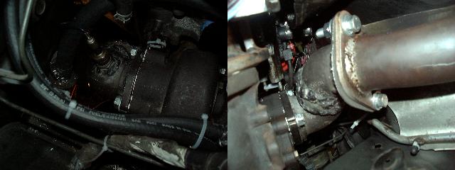
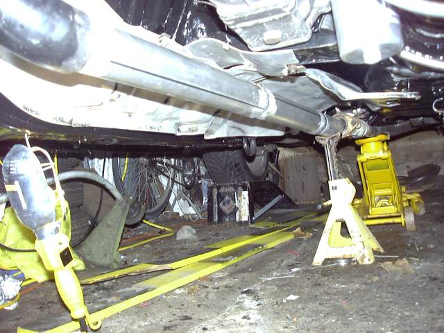
The adapter fit the turbo fine, though it required the use of a very stubby wrench to get to the bolts. I actually ended up just cutting a 17MM wrench in quarters then banging the nuts tight with a hammer and drift. Removal will not be fun. The oxygen sensor was installed (with plenty of anti-seize) and then the downpipe was bolted on from underneath (using a new gasket, with plenty of anti-seize on the stainless bolts and nuts, of course). You will also see in the second picture that the small nipple used to connect the split-air pipe to the 5th and 6th port actuators has been capped. The 5th and 6th ports were tied open, since there is neither a need for them with forced induction, nor is there a way to activate them with the turbo in the way.
While the downpipe adapter did work well for the initial test run of the project, later on I constructed a much better downpipe. The pipe was made using 2.5" SCH 40 weld els, purchased from a local plumbing supplier. These are cheap, easy to weld and almost indestructible. The turbo flange was purchased from Mazdatrix.
The downpipe started off as a 90 degree el from the turbo flange, then connected to a short 4" section of 2.5" SCH 40 pipe, then to another 2.5" el.
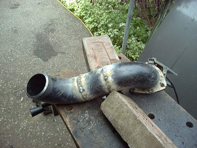
Finishing off, a section of 2.5" exhaust tubing was welded to the downpipe assembly to form a midpipe. The downpipe was made thick to avoid the "pingy" sound that the rotary can sometimes make. The remainder of the system was made of standard exhaust tubing to save weight.
The pictures don't show it but a bung was welded onto the first el for the oxygen sensor.