| Home > RX-7 > My RX-7 > Project Tina > July 18th, 2007: Finishing The Big Turbo Installation and First Startup |
| Home > RX-7 > My RX-7 > Project Tina > July 18th, 2007: Finishing The Big Turbo Installation and First Startup |
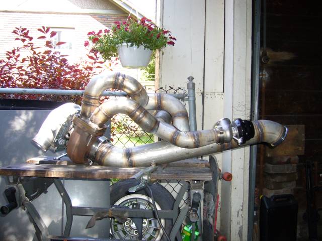
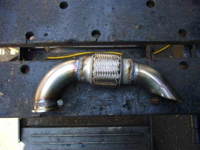
Here's the mockup with the wastegate runners tacked back into place. There is way too much plumbing here! And there's still more to add. Next time, I'm going back to NA...
Time to fully weld the wastegate runners. Some of those angles were a real pain in the butt due to the lack of space. I had to seriously extend the tungsten out of the torch to get at the inner joints which necessitated cranking the gas flow as well to keep the shield. Glad I don't do that very often.
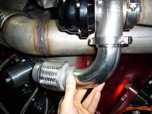
The manifold, turbo and downpipe were then reinstalled on the car and the work on the wastegate dump started. It starts off as an approximately 90 degree bend of 1.5" tubing from the flange, then connects to a short flex section. The flex section is almost necessary as it is absolute hell to reassemble everything without give somewhere. Stainless loves to move when welding and unless there is serious jigging present, stuff isn't going to fit after being full welded no matter how well you tack. Because of this movement, I finish welded every joint before I started work on the next section.
Even though I finish welded every joint as it was made, I did some tacking because the parts kept falling on my head. That gets annoying after a while.
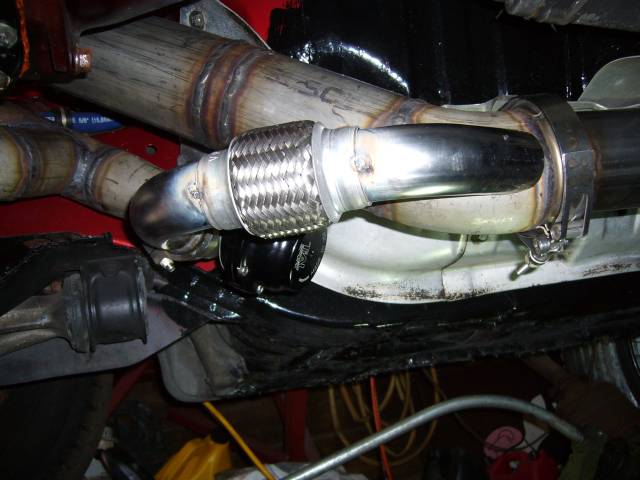
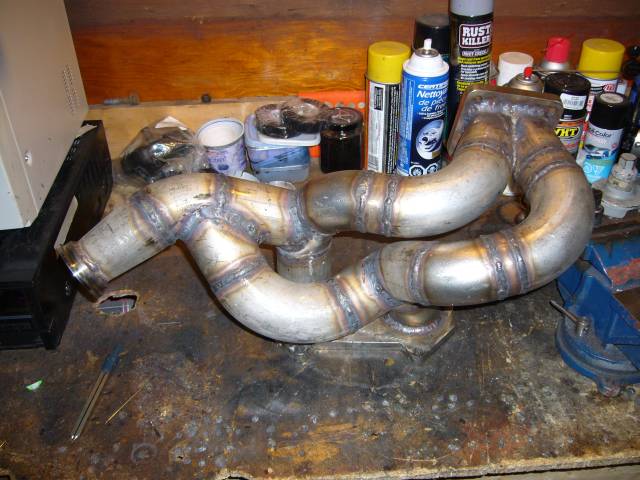
Another view of the wastegate dump.
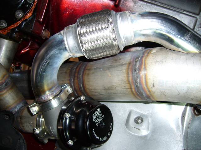
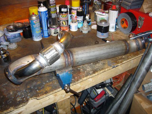
The flex section was then fully welded. I'm a little disappointed with the Vibrant 1.75" Flex Coupling with regards to quality. While the inner pipe and braiding are stainless, the outer crimp section appears to be galvanized steel. And it sure smelled like galvanized steel during welding. The galvanization is very dirty and makes controlling the TIG arc and puddle very difficult. Also that means it will rust down the road, so it will need to be painted.
With the flex section welded, the position on the downpipe was known so the downpipe could then be marked for the cutout. Notice how shallow of an angle the two pipes meet at. It's very important to have the wastegate dump flow smoothly into the downpipe and not become a venturi. But it does mean that welding the inner angle is a pain.
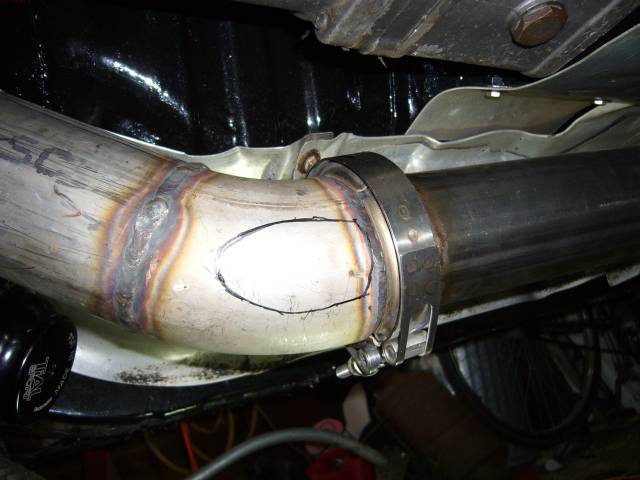
Welding the dump to the downpipe was generally straightforward. A little challenging welding the thin tube to the thick pipe, but this is where TIG really excels. Really, the only annoying part was the V section between the 45 degree bend and downpipe.
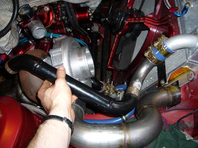
The GT40R dominates the engine bay which necessitated the re-engineering of the upper coolant pipe. The previous pipe basically copied the stock hose and while it did fit, it left absolutely no room for an air filter. After about an hour of trying to figure out the new pipe (including some strange efforts with U bends) I finally got it sorted by adding a 90 degree bend at the radiator, then joining up the original upper pipe at that point. A little bit of modification to the other end and it almost fell into place.
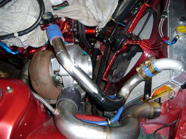
I trimmed down the length of the old pipe and removed the almost 90 degree bend closest to the engine. Then used a small section of a previously cut bend to point the pipe towards the water neck. After that, a short section of straight tube was used. Tacks hold it in place for now.
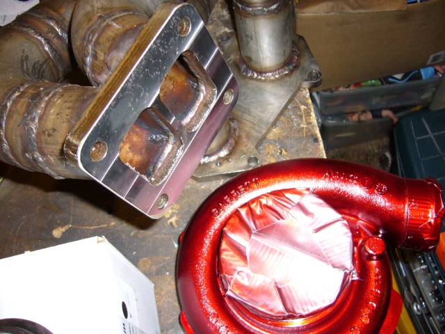
Something that really bothers me is the rust forming on the turbine housing. That rust is just from a few weeks exposure to open air, and handling. Now I know it might be a bit of a nitpick, but when you pay this much for a turbo, you at least expect it to look decent. Is it to much to ask for Garrett use some kind of coating on the castings? Even a thin plating of almost anything would prevent the rust.
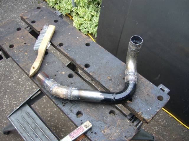
The pipe was then brought over to the bench to be welded. Just before I started working on this pipe I had to take the rental TIG back, so we're back to the trusty flux core wire feeder. Hence the splatter. Nothing that a flap wheel won't cure. Beads were also welded around the ends of the pipe to give the clamps something to grip.
Keeping in mind that this is an NA block, the oil source for the turbo is a bung that I had installed on the oil cooler. The downside of this approach is that the turbo receives unfiltered oil and it is entirely possible for the oil pump to pick up some nasties from the bottom of the pan (gasket sealer, metal chips, etc.). Sending that stuff through a ball bearing turbo would not be my first choice. To combat this problem I decided to use a remote mount oil filter kit as a secondary oil filter. The large -6 feed comes from the cooler, and the small -4 feed goes out to the turbo.
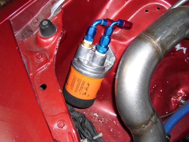
With the lines made up you can see basic idea.
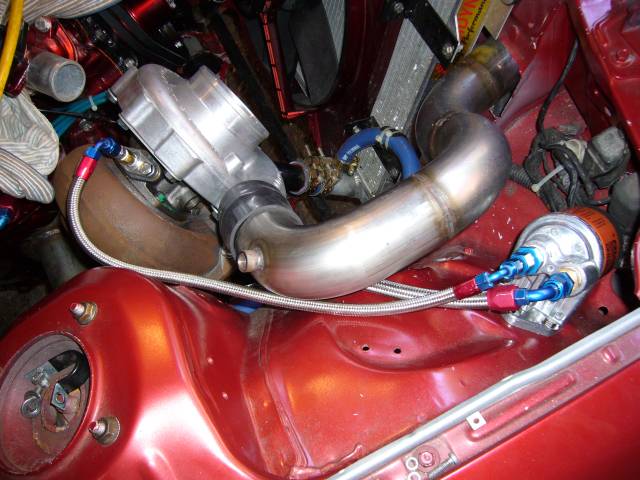
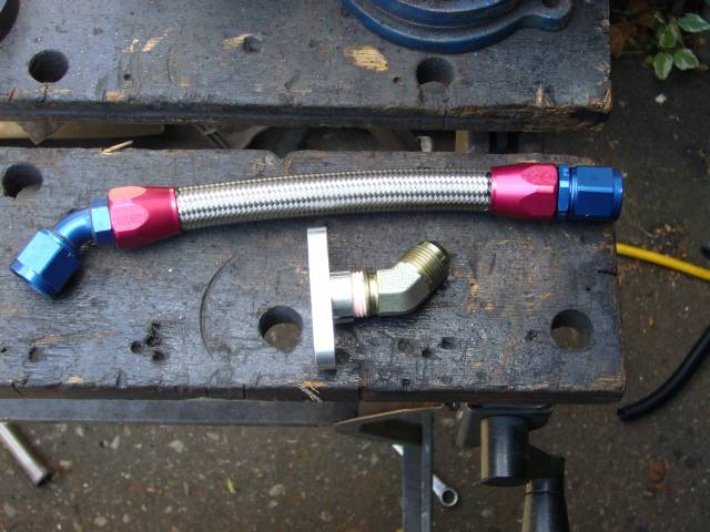
This turbo requires a different drain setup then the stocker, so I made up a new drain line from -10 hose and the appropriate fittings. The drain flange is from ATP Turbo and provides a 1/2" NPT thread for whatever adapter the user chooses. ATP has recently expanded their line of turbo feed and drain flanges to include built in AN flares and restrictors.
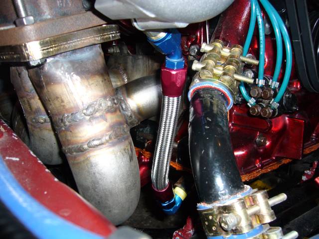
Test fitting the turbo oil line. Maybe some of the photographers around here can tell me how to get decent pictures when using the flash? The flash always blows out the details and makes my welds look disgusting. Also take a look at the wicked warp of the turbo flange...The machine shop guys are going to have fun with that!
Speaking of the machine shop, I'd like to thank Mike Prince of Prince Machine for milling my flanges when no other shop in the city was willing to take on such a small job. He spent a few hours jigging it up and I was very happy with the outcome as well as the $125 cost. He said that he machined it within 0.001, which is certainly acceptable! While the manifold was at the machine shop, I also painted the turbo compressor housing. MetalCast red, naturally.
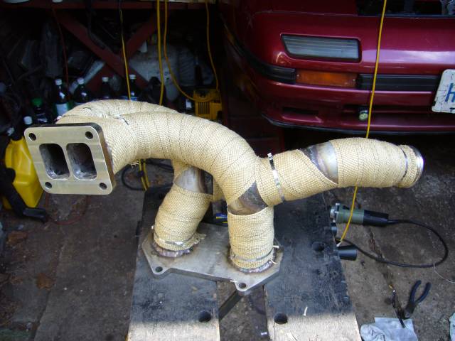
To keep underhood temps sane, I heat wrapped the entire exhaust system. Here's the manifold. The only annoyance with heat wrap is that it's not really designed to cover an area where one pipe merges into another, so there are a few spots left bare. Such is life. Maybe I'll go back later and add another layer.
The key with heat wrap is to get it nice and wet before wrapping. Wrap a few turns on one end and then use a tie to secure it in place. Now pull it tight and continue wrapping to the other end. Hold it tight with your full hand by gripping around the tube and use your other hand to install the tie. When it dries, it will tighten up and won't come off. After the wrap dries, I also wrap the entire piece in bailing wire as an extra measure.