12/120V inverter again
Printed from: Aaron's Homepage Forum
Topic URL: http://www.aaroncake.net/forum/topic.asp?TOPIC_ID=2996
Printed on: May 05 2026
Topic:
Topic author: YS
Subject: 12/120V inverter again
Posted on: Mar 05 2004 10:13:25 PM
Message:
Very popular topic.. Looks like people have problems with this device.
I was wondering about this schematic. Just a mental exercise, you know. What caught my attention is the fact that both tantalum caps showed in - as I think - reversed polarity.
Look at the schematics: the base of the transistor never gets more than 1V above emitter voltage - when the transistor is opened; when the transistor is closed, the base voltage may go well below 0.
The other side of the cap is connected to collector. When transistor opened, it goes to almost 0; but when it is closed, it goes well above 12V (without a diode; 13V with a diode in place).
Therefore, I would connect minus of the caps to bases and plus to collectors. BTW, blowing caps may be just a sequence of wrong polarity..
So, my advice would be - change caps polarity.
Opinions are welcome.
Replies:
Reply author: phoenix
Replied on: Mar 10 2004 08:52:33 AM
Message:
HEY! Thanks 4 the advice...
T-boss
Reply author: Aaron Cake
Replied on: Mar 10 2004 09:57:22 AM
Message:
Uh oh...If I made a mistake, I would like to correct the schematic. But what's odd is that the circuit has always worked for me...unless I was mentally switching the capacitors without realising it...
Anyone else found this as a solution to inverter problems?
Reply author: YS
Replied on: Mar 10 2004 9:31:38 PM
Message:
What is the most intriguing to me - the fact that aluminum caps blow up and tantalums are not. I used to think that tantalums do not survive reverse polarity well - aluminums are better on that. With reverse polarity, a tantalum cap usually acts almost like a diode.
Interesting..
Reply author: tim
Replied on: Mar 13 2004 3:33:12 PM
Message:
with all the questions about that 12v-120v inverter , ive been working on it for months and the circuit does work with the diodes in place. however the problem is with the caps, i tried 100ohm 1watt in place of the 180ohm 1watt with same result and also tried 10watt 10ohm in place of 5ohm 10watt again with same result,low voltage.i tried 25v 68uf tantalums and they instantly exploded , i tried polarized caps and got full power for only about 30 seconds befor they blew.i also tried various transformers , same result. so now im using the 24v ct transformer and the circuit is again complete but still dont have the correct caps to run this thing. now i put a cap bank together that has 5 50v 10uf caps and 1 50v 1uf cap in paralle, thesecaps are all nonpolarized to settle the discussion about caps being in backwards.the 2 caps that go to the circuit i used 50v 68uf nonpolar which by themselves you only get about30-40 volts not acceptable, so i took the cap bank which has 2 sets of the above values and cris-crossed the polaritys from the base to collector and wound up with about65 volts just enough to light a 75 watt bulb but not bright. so if someone tells you that the circuit works with tantalums i think its bull, unless they are not using dipped caps and it calls for something other then dipped tantalums.does anyone out there know what they are doing?
Reply author: YS
Replied on: Mar 16 2004 11:32:09 PM
Message:
Yes. For instance, I do know what I am doing, so I am very cautious about using somebody else's schematics, especially if they seem too simple. The simpler schematic is, the more chances that you will need lot of adjustments and experimenting.
BTW, Aaron mentioned several times in this forum, that this inverter is very critical component-wise, and in my understanding that means you need some good luck with it.
Quote from schematic page: "This circuit can be tricky to get going. Differences in transformers, transistors, parts substitutions or anything else not on this page may cause it to not function."
OK, couple of thoughts to add:
1. Use thick and short wires. It is necessary for such a device.
2. Caps should be reversed IMHO.
3. Caps have certain max current rating. You need caps capable at least 0.2A. So I would use caps designed for switching power supplies. Try Panasonic FC series; for instance, 68uF 50V, available at DigiKey. Part number P11252-ND.
4. I would consider using Darlington pairs instead of transistors. Or, add another two transistors - either medium or the same 2N3055 - to existing ones to produce Darlingtons. That will put great relieve on the caps. There may be other issues though so this is consideration only. And if you doing that do not forget to add base to emitter resistors.
Reply author: Aaron Cake
Replied on: Mar 17 2004 3:02:48 PM
Message:
I think I'll link to this topic via the Inverter page. Should help answer a lot of questions.
Reply author: tim
Replied on: Mar 18 2004 09:17:22 AM
Message:
well if anything the 68uf 50volt nonpolar caps i tried should have worked but they didnt. this circuit i tried 3 times with all said to use including the tantalums but they explode.another site said dont use dipped because they explode, but they did say to use 68uf 50-60volt tantalum but these are can type and grey or silver color but it didnt say if it has to be solid or electrolytic so i dont know.
Reply author: YS
Replied on: Mar 18 2004 09:39:53 AM
Message:
May be I was unclear? Or were you too disappointed to read it through? :)
The caps in this circuit have to pass relatively large current through them and not every capacitor is able to do that. There are special types. a bit more expensive, designed for high pulsing currents. Tantalums generally are more current-capable, but not all of them. See my previous post for the rest.
Reply author: tim
Replied on: Mar 18 2004 4:20:19 PM
Message:
Aaron or YS -- could you please tell me what the next higher power transistor than that of the 2N3055 is? Amperage and voltage. This is to use in this crazy 12V-120V inverter. Thank you...Tim.
Reply author: YS
Replied on: Mar 19 2004 12:44:47 AM
Message:
Tell you the truth, I do not know :). I usually deal with smaller currents.
For me, 15A seems to be pretty good and I do not think your battery will like the bigger currents anyway. 60V is more than enough for this circuit. Well, if you want more, search manufacturer's websites. Start with www.onsemi.com
Reply author: Epsilon!
Replied on: Mar 23 2004 5:42:10 PM
Message:
Would i need to change any resistor values to use darlington transistors,. What if i use a smaller transistor to drive the 2n3055?
Reply author: YS
Replied on: Mar 23 2004 7:06:22 PM
Message:
I wold use something smaller but not too small, not 2N2222. Something with 1A collector current at least.
As for resistors, I would think that as base current will be about 100 times less, you can try to increase R3,R4 maybe to 10K or more and get rid of tantalums. Try 1uF ceramics or film caps..
But that is only my guess, remember that! No responsibility on my part... use it on your own risk :))
Reply author: tim
Replied on: Mar 24 2004 6:43:46 PM
Message:
boy ill tell ya, this inverter circuit has alot of people by the %@@*%#$ you know even me but the first one to get this thing up and running deserves a medal. my latest with this circuit is, a capacitor bank that consists of 10-50volt 10uf nonpolar caps 5 per side with a 100 ohm 1 watt resistor paralled with the caps 1 each side also 2 50volt 68uf nonpolar caps , one is put across both collectors and the other one is put across the bases . im getting 67 volts and it almost turns my 19 inch tv on. so now im waiting for 100volt transistors that might do the trick. i figure the 2n3055 transistors are only good for 60 volts these ones im waiting for is good for over 100volts and there rated for 20 amps not much more then the wussy 3055s. well what the hell its worth a try. and so far nothing is running hot, good sign, and finally this is with the diodes in place like the schematic shows, they have to be otherwise transistors would burn left and right they do shunt back currant.
Reply author: YS
Replied on: Mar 25 2004 9:47:56 PM
Message:
I do not think 60 V is not enough.. on that side of transformer you have only 12V of power, and diodes should protect from flyback voltage.. just a comment :)
Reply author: plutonium233
Replied on: Apr 12 2004 10:51:02 PM
Message:
Should the resistors be wirewound, metal film, or what? What would a good Qx be that could carry 30 + amps. Also, this is a simple squarewave inverter, I think it would be a good idea to work with some PWM and amplitude modulation to at least modify the wave to a rudimentary sine wave for any serious use of this circuit. What voltage should the caps be rated for.? Has anyone verified whether the caps were reverse polarity?
plutonium
Edited by - plutonium233 on Apr 12 2004 10:53:25 PM
Reply author: tim
Replied on: Apr 13 2004 8:23:58 PM
Message:
well if i were you i would quit while i was ahead because this inverter circuit sucks, i have been working on this for months with very little luck meaning only getting 67 volts out of this project. no the the caps go in like it shows and so does the diodes.if you can get this to put out some serious AC then you should get a medal. and also the resistors have to be wire wound. good luck...... tim..
Reply author: n/a
Replied on: Apr 26 2004 06:21:12 AM
Message:
Well just a few comments on the circuit being talked about here. One thing I can tell you all for sure is that Tantalum caps do explode very spectacularly when in a circuit reverse polarity. During my time at an electronics mfg. being involved with testing and troubleshooting, we had regular incidents of tanty caps blowing up like firecrackers when they were in backwards. (Very dangerous as flying hot bits of cap come at you, and the stink !!!)
As for the circuit itself, it does look rather simplistic for an inverter circuit and even I had a bit of trouble trying to analyze how it functions. I haven't had a whole lot of time to go over it but it seems to me like there may be problems with it. If those caps are blowing up on a regular basis then they are definitely in backwards as they are shown in the circuit. But without doing more circuit analysis I can't say for sure what it is but that would be my first guess at this point. Electrolytics like to blow up when enough juice is run through them backwards or even forwards too.
Will do somemore analysis and see if I can't find another schematic for comparison. Chow-fer-now.
12:12
Reply author: n/a
Replied on: May 03 2004 4:31:11 PM
Message:
Hi,
I was just wondering if anybody has ever tried using gate insulated bipolar transistors (IGBT's) in place of the 2N3055's. I have about 10 of these things laying around and they are rated at 900vDC at 60A. I have been thinking about using these in place of the 2N3055's. By the way if the 68UF caps are blowing up wouldn't it be better to use capacitors that can withstand high current DC pulses of electricity?
I just happen to have a few high voltage pulse capacitors that are rated at 40UF, 3KVDc I think they just might be suitable if I add some reverse voltage blocking diodes.
Reply author: tim
Replied on: May 03 2004 7:01:36 PM
Message:
i have tried hi amp bipolar npn transistors, also all differant kinds of caps. i put a cap bank of 5 50 volt 10uf caps together per side and these are nonpolar caps and under a load i still get about 67 volts no load i get 110 volts. its definitly in the type of cap used and i think strongly that it has to be a certain type of tantalum for sure and this circuit will kick ass. thetre are certain types of tantalums but i dont know if its wet or solid but i do know it can not be dipped they blow like firecrackers and this is either way you put them in, ive been there i did it all tring to get this circuit to work.
Reply author: n/a
Replied on: May 03 2004 8:00:46 PM
Message:
Well it doesn't hurt to experiment so I will see what I can come up with. I have one hell of a nice transformer with a 110-120v input and a 26.5v output at 20A.
Reply author: audioguru
Replied on: May 05 2004 10:50:20 PM
Message:
We discussed your Inverter circuit on another site and I have made a detailed analysis which explains the problems that this circuit has:
General
1) The circuit cannot produce anything near 300W.
2) If the parts values and transistor gains are identical, then when it is turned-on both transistors may conduct at the same time and latch-up. Then it will blow the fuse.
3) The capacitors are shown backwards.
4) The capacitors cause the reverse-bias maximum voltage rating of the base-emitter junction of the transistors to be exceeded, causing damage. The capacitors have huge current flow causing them to blow-up.
I have a lengthly, detailed explanation if anyone is interested.
Reply author: YS
Replied on: May 07 2004 08:44:24 AM
Message:
Of course, this circuit is very simple and not ideal - or if so, why should not industry use it?
But it would be interesting to hear detailed explanations. So far, the only good point you made is the second half of #4, currents through caps were discussed.
Others :
#1 - theoretical limit is close to 300W, as the thing produces something close to square wave - and battery voltage is not 12V, as we all know
#2 - invalid. You probably used SPICE for analysis; what about astable multivibrator then? this circuit is just a variation. There are never two identical transistors unless you take special care to make them.
#3 - was discussed already, see the beginning of the topic.
As for reverse voltage, you are right. 7V is the limit and here we may have more - so emitter junction serves as zener diode. It does not necessary hurt transistor, as the current is not too huge, but maybe diodes should be used to protect transistor and reduce heat.
And the last: from the professional point of view, almost any schematic on this site may be criticized for hours and hours.. but they are quite good for amateur purposes. They (almost all of them) may be improved; so, if you see the way to do it, please share with the rest of us.
Regards, YS
Reply author: audioguru
Replied on: May 07 2004 09:54:26 AM
Message:
YS,
Thank-you for your interest, here is my analysis:
Detail and Recommendation
1a) In order to obtain 300W from a 12V battery then the output transistors must conduct 25A each. But the 2N3055 listed transistors have a maximum rating of only 15A and are spec'd to only 10A. Therefore paralleled transistors are required, with emitter resistors to equalize transistor gains.
1b) The 2N3055 transistor has a guaranteed gain of only 5 at 10A of collector current and even less at higher currents. Since the 180 ohm base-drive resistor gives only 62mA, then the gain of the transistors must be at least 403. Therefore driver transistors are required.
1c) Actually, in this circuit, using 2N3055 transistors having minimum gain of about 50 at 3A of collector current, the 62mA of base-drive from the resistors results in 3.1A of collector current. Therefore the power of the circuit is 37.2W, much of which is spent heating the capacitors and damaging the base-emitter junctions.
2) I have seen it happen, when I selected parts to make a simple multivibrator like this one produce 50-50 symmetry. The oscillator locked-up occasionally. The use of a 4047 oscillator/divider is recommended along with pre-driver transistors.
3) The collectors of the transistors are mostly positive, and the bases are near ground potential. Reverse the polarity of the capacitors.
.4) Most silicon transistors have a maximum reversed-biased voltage rating of about 7V. At that voltage, the base-emitter junction avalanches, like a zener. The avalanching burns holes in the junction, reducing its gain. The amount of damage is related to the size of the junction and the transistor's gain.
Capacitors have a "ripple current rating" which is related to their internal impedance (resistance) and physical size (to dissipate power) similar to a power resistor. The ripple current rating can be exceeded with high AC current.
In this project, the capacitors are charged to nearly 23V with a very high current flowing through a forward-biased base-emitter junction on one side, and the +24V (center-tapped transformer action) from the transformer on the other side.
The capacitors are partially discharged with a very high current through a saturated collector on one side, and an avalanching (-7V) base-emitter junction on the other side. When the capacitor voltage discharges to less than 7V then it can continue a slow dicharge through the resistor, for its timing period.
Therefore the capacitors have very high currents flowing in them which causes "ordinary" capacitors to explode. Separate oscillator and output drive circuits are recommended.
Reply author: wasssup1990
Replied on: May 09 2004 03:59:44 AM
Message:
Shyt! Some very long replies hear. I remember when i first saw this site, i was looking for an inverter schematic on google, and it came up with this site. I looked at the schematic and said to myself, "Its to simple? how could it work." Even if you did get it to work it would take a long time, thats why i'm building my own.
Reply author: YS
Replied on: May 12 2004 9:36:28 PM
Message:
Not too easy, eh?
Reply author: wasssup1990
Replied on: May 13 2004 01:57:09 AM
Message:
Certainly not!! Trying to get an energy level out of another enrgy level will allways be hard.
Reply author: shivick21
Replied on: May 25 2004 08:39:34 AM
Message:
heheheh hi again! so figured it out how does thing work? i am very intriuge about that coz i want to have that thing to!! wahehehe if anyone has/have a working diagram, pls post. hehhe so i can use my pc even the power went out like i posted earlier. (converting atx pc power supply) thats all again. thanks.
Aki-kun
Reply author: n/a
Replied on: Jun 02 2004 03:44:27 AM
Message:
Well, I built one, and I have a couple of dead 3055 transistors to show for it.
I don't have the tantalum caps (I remember thinking that they looked like popcorn kernels when I soldered them onto my prototype) because I never bothered recovering all of the fliff when they exploded.
Actually, I'm not looking for 120V from it, more like about 30, and no more than a couple of amps. What I want to do with it is to make a symmetric power supply, +/-15V for some audio circuits.
Eventually, I'd like to try something that's more along the lines of +/-35V and about 8 or 9A for a small amplifier, but that's a "down the road" idea, so to speak. Not much more than the 100W range, in any case.
The oscillator locking up would be a problem, but the power limitations should not be.
I may try this again with a 2N2222 as a driver for a darlington pair.
Or, I may just use an admittedly much more complicated SMPS based on an SG3524 controller chip...
Reply author: audioguru
Replied on: Jun 02 2004 09:10:01 AM
Message:
SupraGuy,
Sorry to hear your experience with this bad circuit.
For your applications, why not keep it supra-simple:
1) A CD4047 oscillator/divider/opposing-outputs chip as the oscillator-driver. It needs only 1 resistor and 1 capacitor. Its outputs are perfectly symmetrical, and are direct and inverting.
2) A pair of power MOSFETS with built-in zener protection diodes as the output transistors.
3) A regular 50Hz or 60Hz center-tapped transformer, or a smaller high-frequency one.
300W would be easy.
I would post a circuit but I don't need another power supply. Why don't you?
Reply author: n/a
Replied on: Jun 02 2004 4:32:55 PM
Message:
Hmmm... Reading through, I was looking at wassap's inverter schematic, and came up with a variation. I removed the temperature regulation, and the push-button start, and added in some noise rejection, and overvoltage protection (I know what happens at the alternator when you turn off the headlights!) Hopefully this would be quiet enough for audio circuits.
I've put up the schematic at http://www.abstractconsulting.com/~dan/images/Inverter.gif
Please pardon my cheapo schematic drawing program. :)
The entire oscillator section was grabbed wholesale. I want to adjust the switching frequency upwards, and I plan on adding some large capacitors to the supply, which should also allow me to eliminate the input choke.
I took a brief look, but could not find a CD4047 part available. Ah. Nevermind. I just checked TI. :)
Most of the trouble that I seem to have when dealing with SMPS for a car supply is sourcing the transformers, or even just a core that I can wind myself. Nowhere local carries them, and I can't seem to order them from digikey, either. I know that such things exist, I just can't find 'em.
Reply author: audioguru
Replied on: Jun 02 2004 10:20:11 PM
Message:
SupraGuy,
You just copied Wasssup's complicated circuit and are even using his obsolete MOSFETs.
Since you found a TI CD4047, don't you like my simple idea?
I agree that high-power transformers are hard to find. Buy them from an inverter manufacturer.
Reply author: n/a
Replied on: Jun 03 2004 02:54:03 AM
Message:
Well, yes. And I started the complicated one before I got to the "simple"
I can't find direct info on the R/C relationship to set frequency, so it's hard to choose component values, but having the pins labelled "R", "C", and "RCCOMMON" is a big hint as to where to put stuff. :) I'd guess that Q and Q' are the opposing outputs, but I'm missing information as to what voltage/current I can expect at the outputs. I'm working on a schematic working on the assumption that I can have a couple of mA at close to the supply voltage. I'm not all that great on reading the data sheets, so It's more than possible that I'm wrong. :P
If I can have reasonable voltage, I'd rather use (inexpensive) transistors, rather than big MOSFETs. Also, since I'm looking for considerably less than 300W (At least at first) something really common like 2N3055 transistors (Which I have a bunch of already, making them even cheaper.) Well, let's start from a minimalistic KISS principle, and add headaches from there.
Reply author: n/a
Replied on: Jun 03 2004 04:29:00 AM
Message:
Okay. New attempt at http://www.abstractconsulting.com/~dan/images/Inverter2.gif
Probably full of flaws. Let me know what they are! :P
Reply author: audioguru
Replied on: Jun 03 2004 07:32:42 AM
Message:
SupraGuy,
Problems? Yea:
1) The R pin of a 4047 is rated for a minimum of 10K, so your R1 is 100 times too small. Use 39K or 47K.Therefore its capacitor, C3, is way too big. Use 0.1 microfarads.
2) The 4047 does not like to drive the dead-short-load of a transistor's base-emitter junction, so add resistors in series with its outputs to the transistors' bases.
3) The 4047 can provide about 12mA from its outputs on a 12V supply, so a 2N3055 that it is driving through a resistor will conduct a minimum of only 360mA. The power ouput of your inverter is only 3.5W
4) Your D2 and D3 protection diodes are a dead short across the transformer. Since the transformer's center-tap is at +12V, then transformer action defines that if 1 side is driven to ground, then the other side will swing to +24V. That's why we are using a 24V transformer with a 12V battery
5) Where are you going to find a transformer with such a small voltage ratio?.
Use Google to see the data sheets for CD4047 and 2N3055.
You have lotsa 2N3055s? Here is a 700W (coservatively rated at only 500W by artist) that I helped design:
http://www.electronics-lab.com/forum/attachments/500Watts_Inverter.gif
.
http://www.electronics-lab.com/forum/attachments/500Watts_Inverter.gif
Reply author: shivick21
Replied on: Jun 03 2004 07:59:07 AM
Message:
neat!!have you build this one? does it work? the parts are much easier to find but,,,, i have the 2N3055 Surface mounted transistor, now how do i suppose to put this thing? in your diagram the base itself is conneted to another 2 transistor so where and how could i mount this thing? and those this thing emmits heat? like the usual transistor? and one ither thing, pcb boards? du have a ilistration? hehe thats all
Aki-kun "Pls! tank me! Im a noobs"
Reply author: audioguru
Replied on: Jun 03 2004 3:16:56 PM
Message:
To All,
The first 500W inverter was reported today, to deliver 780W output:
(Qupte)
Topic Summary
Posted by: Chip Posted on: Today at 12:19:24pm
Audioguru
Inverter is working fine at 780W
I will send a picture of this monster as soon as it will be in the box. I have added a charging circuit for battery which can charge at 6A from solar cells.
Well I coudn`t get the 70amp power switch so I put only a tiny switch for control part of the inverter and it works fine.
(Quote)
.
Reply author: n/a
Replied on: Jun 03 2004 11:31:06 PM
Message:
Okay... If that inverter works so well, it would make sense to just use it. :) Just gotta get a transformer to work with.
I did fix most of the problems with the circuit (I think.)
New schematic at http://www.abstractconsulting.com/~dan/images/Inverter3.gif
Reply author: shivick21
Replied on: Jun 05 2004 12:34:15 PM
Message:
hi, does this inverter u post is working? or have u tested it to work on specific components? eg for pc?
Aki-kun "Pls! tank me! Im a noobs"
Reply author: audioguru
Replied on: Jun 05 2004 2:17:38 PM
Message:
SupraGuy,
Your circuit still has problems:
1) Q5 and Q6 turn-off the output stages, but there is nothing to turn them on.
2) "Your D2 and D3 protection diodes are a dead short across the transformer. Since the transformer's center-tap is at +12V, then transformer action defines that if 1 side is driven to ground, then the other side will swing to +24V. That's why we are using a 24V transformer with a 12V battery". As I explained before.
Reply author: n/a
Replied on: Jun 05 2004 6:20:38 PM
Message:
Heh.
1) Oops.
2: D'OH! I'd fixed it, then "fixed" it again. Gotta stop working on this stuff at 2 AM.
Reply author: n/a
Replied on: Jul 25 2004 09:58:41 AM
Message:
I'm a little new to this power inverter thing, but if all you want is rough sine wave, couldn't you use a 555 timer with low voltage RC circuit for rounding the wave form, then amplify it, then step it up with T1? Is that a bad approach? I can see how pushing large current through any type of cap is going to cause problems sooner or later.
Also, you guys who are looking for some large transformers might need to look at old ham radio equipment power supplies. Even burned out ones usally the transformers are good and of the voltages/current you can use believe.
Edited by - frankswd on Jul 25 2004 10:10:14 AM
Edited by - frankswd on Jul 25 2004 10:17:20 AM
Reply author: audioguru
Replied on: Jul 27 2004 7:42:41 PM
Message:
Frank,
Why do you need a sine-wave? Heaters, motors and lights don't care if it is an efficient square-wave.
If you amplify a sine-wave, then the amplifier will heatup a lot since its output is near "halfway" most of the time. Since a square-wave inverter switches fully-on and fully-off, it is much cooler. The wasted heat from a sine-wave inverter runs-down its battery sooner.
Besides, the amplifier will need a very high current output.
Edited by - audioguru on Jul 27 2004 7:45:51 PM
Reply author: marius
Replied on: Jul 28 2004 09:17:26 AM
Message:
But what about TV's, radions and other similar appliances ? Can they work with your suggested schematics from here ?
http://www.electronics-lab.com/forum/attachments/500Watts_Inverter.gif
quote:
Frank,
Why do you need a sine-wave? Heaters, motors and lights don't care if it is an efficient square-wave.
If you amplify a sine-wave, then the amplifier will heatup a lot since its output is near "halfway" most of the time. Since a square-wave inverter switches fully-on and fully-off, it is much cooler. The wasted heat from a sine-wave inverter runs-down its battery sooner.
Besides, the amplifier will need a very high current output.
Edited by - audioguru on Jul 27 2004 7:45:51 PM
Marius
Reply author: n/a
Replied on: Jul 28 2004 11:51:06 AM
Message:
most devices will work fine with a square wave inverter. Almost any semicondictor based device (TV, Radio, computer, etc) juist uses a tranformer to conver the voltages to the desired values, ten rectifies it to DC anyway, after which it doesn't matter what the original waveform was. (It also doesn't matter what the frequency of the AC signal was, either.)
Reply author: audioguru
Replied on: Jul 28 2004 11:54:04 AM
Message:
Marius,
That 500W inverter is used to power TVs and flourescent lights.
Reply author: audioguru
Replied on: Jul 28 2004 12:27:24 PM
Message:
SupraGuy,
Many electronic devices use the peak of the mains AC voltage to develop their DC supply voltage. That inverter will not supply enough voltage to them. The TVs that are used with it are international and work from 85VAC to 250VAC.
Reply author: marius
Replied on: Jul 28 2004 12:40:44 PM
Message:
Thanks.
I have two additional questions, with your permission:
1. Do you know if most of the commercial converters (30$ to 100$) which do similar tasks uses square wave or sine wave ?
2. CD4047 is not easy to find. Is there a special reason for choosing this one or can I switch it with a 555 and a NOT gate ?
Thanks in advance!
quote:
Marius,
That 500W inverter is used to power TVs and flourescent lights.
Reply author: audioguru
Replied on: Jul 28 2004 7:57:19 PM
Message:
Marius,
All cheap commercial inverters have square wave output. Sine wave ones use either a big, special "tuned" transformer or a lot of hot and expensive transistors on a big heatsink
The 4047 was chosen because it has a built-in digital divider that gives exactly 50-50 duty cycle, and has opposing outputs. A 555 and inverter will be OK.
Reply author: marius
Replied on: Jul 29 2004 06:53:22 AM
Message:
Thanks again.
Now, since 500W on the secondary winding are more than 40 amps on the primary winding (of the transformer), and since we're dealing with such huge currents, it'll be very interesting to see how have you implemented it - diameter/types of wires, heatsink for the transistors (which cannot be mounted on the box for cooling, since there are two square waves with a series of transistors for each of them. Meaning you can't short the collectors by mounting them on the box).
Since it's working for you, maybe you have a photo of this inverter so we can see how did you choose to implement it (if not, that's ok too, you've been very helpfull already).
Thanks.
Reply author: audioguru
Replied on: Jul 29 2004 11:08:33 AM
Message:
Marius,
I have never built an inverter. I just helped re-design that one, since the original project had errors and didn't work.
All the guys who built the modified one didn't post pics yet
Of course it needs a big output transformer, heavy primary wiring and big heatsinks with proper insulators..
Reply author: phoenix
Replied on: Jul 31 2004 12:02:08 PM
Message:
I'm finding it really difficult finding large transformers...
Does anybody know how (wire diameter) I could rewound an old transformer? I've already tried it once ... not so good...
Thanks...
Reply author: n/a
Replied on: Aug 12 2004 7:08:36 PM
Message:
Hey, I was wondering where I could find those specific diodes mentioned on the schematic? If I can't find them anywhere, what are there specifications?
Reply author: audioguru
Replied on: Aug 12 2004 8:14:28 PM
Message:
Hi Drummerman,
Which inverter are you building? We have been talking about many different circuits here.
Reply author: n/a
Replied on: Aug 15 2004 11:08:59 PM
Message:
I was talking about the schematic that arron cake made. I want to find those HEP 154 diodes. I can't find them anywhere. If anyone could help me find them that would be great. If they don't exist, can someone tell me the specs that a diode would have for that particular circuit? Thanks.
Reply author: audioguru
Replied on: Aug 18 2004 8:31:24 PM
Message:
That project doesn't work. Read this thread.
Reply author: n/a
Replied on: Sep 14 2004 4:51:14 PM
Message:
so would i be able to use this inverter to power a PS2 and an LCD monitor? does the fact that the inverter outputs 220V make a difference?
Reply author: audioguru
Replied on: Sep 14 2004 9:44:17 PM
Message:
Bloodlust,
Which inverter outputs 220V?
If an inverter project works, you can build it to give nearly any output voltage by your selection of its output transformer. Many electronic products don't work when powered by an inverter that has a square-wave output.
The only difference that will happen to a product when you to apply a power supply voltage that is much too high, is that of course it will simply blow-up!
Reply author: n/a
Replied on: Sep 27 2004 4:42:14 PM
Message:
Well your correct. This circuit only uses 1/2 of a 24 Vac secondary used as a primary. This was wound with a ratio for 24 Vac to 120 Vac, not 12 Vac to 120 Vac. 60 to 65 Vac is all it will and can produce! To get the required 120 Vac, you need a 24 Vac C.T. transformer with a 240 Vac primary. This will give the correct ratio amd a 120 Vac output. =)
quote:
I do not think 60 V is not enough.. on that side of transformer you have only 12V of power, and diodes should protect from flyback voltage.. just a comment :)
-=Will Matney=-
(Edit...Remove email notification due to bad address...)
Edited by - Aaron Cake on Nov 25 2005 09:10:59 AM
Reply author: audioguru
Replied on: Sep 27 2004 6:37:10 PM
Message:
Hi Will,
If the inverter works properly (I don't know which circuit that you are talking about), the 24V winding's center tap is connected to +12V, so when a transistor grounds one side then the other side will swing to +24V. Select a 24V center tapped transformer that has a high voltage winding that is rated for whatever output voltage that you need, not double what you need.
To get 120VAC output, choose a 120V to 24V ceter-tapped transformer, which is also written as 120V to 12-0-12.
Reply author: n/a
Replied on: Sep 27 2004 7:13:25 PM
Message:
By analyzing the circuit, there's a few problems, One bad, and the other not that bad. First, the capacitors polarity is wrong. The + side goes towards the collectors. Next, the frequency is a little too fast. It will run at 102 Hz. Also, 100 ohms I think is a shade too small for the base current needed. Using a 47 uF capacitor and a 220 ohm resistor will give you about 67 hz which is close enough.
I read, but forgot from whom, mention about transistors matching. This is aboslutely what you do not want. Fot the circuit to oscillate correctly, one transistor has to start to conduct before the other. Two exactly matched transistors would lock the circuit up. Another thing that can help this circuit is simply adding a 10 ohm resistor in one of the transistors base leads between the base and the 220 ohm resistor which replaces the 100 ohm ones. This will cause a slight mis-match and help the oscillation start. Next, Remove the other two reisitors and diodes. Then, place some 24 V, 5 Watt zener diodes across the transistors collectors and emitters. This will kill any spikes from the transformer that may be generated. That's how the spikes were killed in the old days.
You might think of changing the 2N3055 to a 2N3772. This will raise the collector current up from 15 amperes to 20 amperes. The 2N3772 is good for about 9 -10 amperes for this type of switching and the 2N3055 about 5 amperes. Those ratings higher are for a 5 Vdc collector voltage and drop off as the voltage raises. You need to look at the spec sheets and see the de-rating charts for power verses voltage.
The formula for the frequency is; f = 0.7/R x C
R in ohms and C in farads.
Will Matney
PS,
One last thing. You might make an astable multivibrator up like this using a couple of 2N2222's then drive the 2N3055's or 2N3722's. The RC value will stay the same.
-=Will Matney=-
(Edit...Remove email notification due to bad address...)
Edited by - Aaron Cake on Nov 25 2005 09:11:47 AM
Reply author: n/a
Replied on: Sep 27 2004 7:21:45 PM
Message:
It was my understanding they were using a 12 Vac, center tapped primary. This would then be a 6-0-6. It sounds to me like this is where somes problems were by only obtaining 65 Vac. For a 6-0-6, you would need the 240 Vac secondary to get 120 Vac output.
The terms primary and secondary are reversed here so as not to confuse anyone. The actual transformer will have a 12-0-12 (24 Vac, C.T.) secondary and a 120 Vac primary.
Will
quote:
Hi Will,
If the inverter works properly (I don't know which circuit that you are talking about), the 24V winding's center tap is connected to +12V, so when a transistor grounds one side then the other side will swing to +24V. Select a 24V center tapped transformer that has a high voltage winding that is rated for whatever output voltage that you need, not double what you need.
To get 120VAC output, choose a 120V to 24V ceter-tapped transformer, which is also written as 120V to 12-0-12.
-=Will Matney=-
Edited by - Will on Sep 27 2004 7:36:45 PM
Last time I'll edit, I just cant spell this evening!
Edited by - Will on Sep 27 2004 7:38:18 PM
(Edit...Remove email notification due to bad address...)
Edited by - Aaron Cake on Nov 25 2005 09:12:35 AM
Reply author: audioguru
Replied on: Sep 27 2004 9:26:55 PM
Message:
Hi Will,
Didn't you read my analysis of this website's 12V to 120V Inverter project that I posted here in May?
Are you talking about people getting an output of only 65VAC into a 75W load?
This simple circuit cannot give much output because the transistors do not have enough current gain and are being forced into avalanch breakdown of their reverse-biased base-emitter junctions.
To provide 75 Watts, the 13.5V battery must supply a current of 5.6A. Each transistor in the inverter must switch this 5.6A through its side of the transformer winding. At 5.6A of collector current, a 2N3055 transistor has a typical current gain of 25, so its base current will be 224mA. But the 180 ohm base drive resistors can supply only 68mA!
With 68mA of base current, the collector current of a typical 2N3055 transistor is only about 3A. So the typical output power is only 40.5W, much of which is used to heat the capacitors and to cause avalanch breakdown of the transistors.
This circuit doesn't work!
Reply author: n/a
Replied on: Sep 27 2004 10:15:23 PM
Message:
I hadn't went to look and see what the gain was on the 2N3055. No, I didn't read your post as I just seen the one having problems with a 65 vac output.
If 224 mA is needed then change the resistors to 47 ohms and raise the capacitance to 220 uF. That will give 255 mA with a 67 Hz frequency. Don't see why it won't work if the base current is large enough and as long as the frequency is 60 Hz +. If the voltage rating on the capacitors is large enough, they shouldn't fail providing they're connected with the right polarity. The max on one should be 12 volts with an allowable 24 Vdc peak which is held by the zeners I mentioned. The series resistor-diodes are not needed then.
Will
quote:
Hi Will,
Didn't you read my analysis of this website's 12V to 120V Inverter project that I posted here in May?
Are you talking about people getting an output of only 65VAC into a 75W load?
This simple circuit cannot give much output because the transistors do not have enough current gain and are being forced into avalanch breakdown of their reverse-biased base-emitter junctions.
To provide 75 Watts, the 13.5V battery must supply a current of 5.6A. Each transistor in the inverter must switch this 5.6A through its side of the transformer winding. At 5.6A of collector current, a 2N3055 transistor has a typical current gain of 25, so its base current will be 224mA. But the 180 ohm base drive resistors can supply only 68mA!
With 68mA of base current, the collector current of a typical 2N3055 transistor is only about 3A. So the typical output power is only 40.5W, much of which is used to heat the capacitors and to cause avalanch breakdown of the transistors.
This circuit doesn't work!
-=Will Matney=-
(Edit...Remove email notification due to bad address...)
Edited by - Aaron Cake on Nov 25 2005 09:12:44 AM
Reply author: audioguru
Replied on: Sep 28 2004 04:23:26 AM
Message:
Hi Will,
That is a good idea. If you use 47 ohm base resistors then this inverter that uses typical 2N3055 transistors should have an output power of a whopping 75 Watts!
You can expand your theory further if you use only 6 ohms for the resistors so that the base current is 2A. Now there will be enough base current so that even 2N3055 transistors that have their minimum guaranteed gain of only 5 will have a collector current of 10A, and the inverter's output will be 120W.
Now that we are talking about 10A collector current, we must not forget that the transistors are part of the oscillator, and have capacitors that must charge and discharge into the transistors' bases. Using 6 ohm resistors, those capacitors will be huge. When the 1st transistor conducts, it turns off the 2nd transistor by its collector cap. When the 2nd transistor turns off, its collector voltage rises to about 27V by center-tapped transformer action. The cap that is connected from the 2nd transistor's collector to the 1st transistor's base must charge without any current-limiting and its current will exceed the 7A maximum base current rating of the 1st transistor for a moment. You could add 3.9 ohm resistors in series with the caps to limit the momentary base current to about 6.7A.
Do you understand about avalanch breakdown of a silicon transistor's reverse-biased base-emitter junction? All silicon transistors have a maximum reverse base-emitter voltage rating of about 7V, whtch if exceeded causes the junction to avalanch like a zener diode and conduct massive current. This current creates hot-spots on that junction that is not cooled well by the transistor's case since the other junction's collector is bonded to the case.
That is bad news for the transistor since a massive current flowing through an uncooled base-emitter junction that has about 7V across it creates a very high temperature at that junction. Poof!
What about the ripple-current rating of the capacitors? That is what caused them to blow-up (even with the correct polarity) in the original circuit. Using 6 ohm resistors, the charge and discharge currents of the caps will be huge. Poof!
So most of the power from this inverter will be used to destroy its transistors and capacitors, and very little power will remain for its load.
It might work a lot better and with improved reliability if the transistors are replaced by Mosfets.
Reply author: audioguru
Replied on: Sep 28 2004 05:45:04 AM
Message:
Hi again Will,
I forgot to explain how avalanch breakdown occurs in this circuit.
When the 1st transistor conducts, the capacitor at its collector has been charged to 27V, and the cap's end that is connected to the 2nd transistor's base will attempt to drive the base to about -26V. The cap is very quickly discharged with a very high current because it has a high-current collector of the 1st transistor driving its other end, and the avalanching base-emitter junction of the 2nd transistor is limiting its negative end. So lots of current through the cap and lots through the junction. Poof! Poof!
The other cap and junction have the same problem. Poof! Poof!
This simple inverter is just a poof-maker and is good only for self-destruction!
Reply author: n/a
Replied on: Sep 28 2004 10:01:29 AM
Message:
quote:
Hi Will,
That is a good idea. If you use 47 ohm base resistors then this inverter that uses typical 2N3055 transistors should have an output power of a whopping 75 Watts!
You can expand your theory further if you use only 6 ohms for the resistors so that the base current is 2A. Now there will be enough base current so that even 2N3055 transistors that have their minimum guaranteed gain of only 5 will have a collector current of 10A, and the inverter's output will be 120W.
>> I don't think a 2N3055 will do 10 amperes at 12 Vdc. Without looking at the spec sheet, this min. current rating starts to drop off at 5 Vdc. The most I've ever seen them used at was 5 amps IC for 12 Vdc circuits.
Now that we are talking about 10A collector current, we must not forget that the transistors are part of the oscillator, and have capacitors that must charge and discharge into the transistors' bases. Using 6 ohm resistors, those capacitors will be huge.
>> Yes, your correct. The 10 amp rating for one 2N3055 I don't think will work. That Will in fact go up in smoke. Personally, I've never seen one used in any power circuits with a collector current of over 5 amperes or so. That's why I was holding it back. If I were to want 10 amperes IC then I'd use two in parallel.
When the 1st transistor conducts, it turns off the 2nd transistor by its collector cap. When the 2nd transistor turns off, its collector voltage rises to about 27V by center-tapped transformer action.
>> It will actually be higher than this at turn on because of the spike created from the sudden shift in the windings. Thus, the zener diode clamps across the collectors and emitters will throw this to ground and hold it at a reasonable amount. They would have to be at least 24 V + 1 or 2 volts.
The cap that is connected from the 2nd transistor's collector to the 1st transistor's base must charge without any current-limiting and its current will exceed the 7A maximum base current rating of the 1st transistor for a moment. You could add 3.9 ohm resistors in series with the caps to limit the momentary base current to about 6.7A.
>> Exactly. If the base current is not limited, it will run away and destroy the transistor. I'd prefer to use two 2N3055's at each side for this and limit each to 1/2 the current. Here would be a good place to implement that kick start thing I was mentioning. Use a 33 ohm on one base and say a 39 ohm on the other. The slight difference will cause the circuit to always oscillate and not latch up.
Do you understand about avalanch breakdown of a silicon transistor's reverse-biased base-emitter junction?
>>I reckon I do, if not, I flushed two years of school and 23 years experience down the toilet.
All silicon transistors have a maximum reverse base-emitter voltage rating of about 7V, whtch if exceeded causes the junction to avalanch like a zener diode and conduct massive current.
>>Yes it does, this has to be limited in the circuit.
This current creates hot-spots on that junction that is not cooled well by the transistor's case since the other junction's collector is bonded to the case.
That is bad news for the transistor since a massive current flowing through an uncooled base-emitter junction that has about 7V across it creates a very high temperature at that junction. Poof!
What about the ripple-current rating of the capacitors? That is what caused them to blow-up (even with the correct polarity) in the original circuit. Using 6 ohm resistors, the charge and discharge currents of the caps will be huge. Poof!
>>Use a large enough, and correct type of capacitor. When the voltage rating of an electrolytic is increased, so is it's current capacity. This is done by increasing the plates size and the coating thickness on the one plate (anode). Let's say for practical purposes, use a 220 uF @ 450 Vdc cap instead of a 220 uF @ 35 Vdc. The difference in physical size is huge. The larger cap will dissipate heat way better and would probably hold up I would think. I forget what the current carrying capacity is for that cap but it's a good amount. This type I'm speaking of is the radial screw top, computer types.
So most of the power from this inverter will be used to destroy its transistors and capacitors, and very little power will remain for its load.
It might work a lot better and with improved reliability if the transistors are replaced by Mosfets.
>> The Mosfets is a good idea because they're voltage dependant, not current dependant. The capacitance polarity and spikes still have to be corrected though as above.
Will
-=Will Matney=-
(Edit...Remove email notification due to bad address...)
Edited by - Aaron Cake on Nov 25 2005 09:12:55 AM
Reply author: n/a
Replied on: Sep 28 2004 10:09:55 AM
Message:
See the explanation in the first post.
The thing is, between you and I, we've about re-designed the entire circuit for the user which I didn't intend to do. I would rather them learn from it and we give help as needed. I'm afraid by about re-designing the whole thing here, some will not learn that much and just build what we tell them to.
There was one person on here who mentioned paralleling a bunch of capacitors in place of one. He was on the right track because the current rating was going up. However, I hope he knew this by learning from the experience and not us telling it.
Will
quote:
Hi again Will,
I forgot to explain how avalanch breakdown occurs in this circuit.
When the 1st transistor conducts, the capacitor at its collector has been charged to 27V, and the cap's end that is connected to the 2nd transistor's base will attempt to drive the base to about -26V. The cap is very quickly discharged with a very high current because it has a high-current collector of the 1st transistor driving its other end, and the avalanching base-emitter junction of the 2nd transistor is limiting its negative end. So lots of current through the cap and lots through the junction. Poof! Poof!
The other cap and junction have the same problem. Poof! Poof!
This simple inverter is just a poof-maker and is good only for self-destruction!
-=Will Matney=-
(Edit...Remove email notification due to bad address...)
Edited by - Aaron Cake on Nov 25 2005 09:12:57 AM
Reply author: audioguru
Replied on: Sep 28 2004 11:12:32 AM
Message:
Hi Will,
Yeah, I have built unbalanced multivibrators too, to guarantee start-up.
But when used with a supply voltage more than 5V, I always add diodes in series with the emitters to prevent avalanching.
I don't think that limiting the current during avalanching is good enough, after all, the manufacturers just say, "Max reverse base-emitter voltage is 7V. Don't exceed it". In my book that means "Dont do dat!"
The users won't learn much when authors post projects like this one, then say to use more powerful trasistors and transformer to get more output. Only the guy who tried 300V/30A transistors and a rewound transformer from a microwave oven learned that it didn't make any difference.
Reply author: audioguru
Replied on: Sep 28 2004 11:45:03 AM
Message:
BTW, Will,
The 500W inverter project that I fixed was reported to deliver 720W. So its output transistors must have had an emitter current of almost 15A.Since its driver transistos were connected in a darlinton arrangement, they probably had a collector current that exceeded that of the output transistors, and all currents went into the transformer. I would never push transistors so hard, therefore rated the circuit at only 500W.
The link to that schematic is posted again here:
http://www.electronics-lab.com/forum/attachments/500Watts_Inverter.gif
Reply author: n/a
Replied on: Sep 28 2004 12:09:55 PM
Message:
quote:
Hi Will,
Yeah, I have built unbalanced multivibrators too, to guarantee start-up.
But when used with a supply voltage more than 5V, I always add diodes in series with the emitters to prevent avalanching.
I don't think that limiting the current during avalanching is good enough, after all, the manufacturers just say, "Max reverse base-emitter voltage is 7V. Don't exceed it". In my book that means "Dont do dat!"
>> Actually, the diodes off the emitters is a good idea and I forgot about that myself. Anyhting to keep the transistor from breaking down.
The users won't learn much when authors post projects like this one, then say to use more powerful trasistors and transformer to get more output. Only the guy who tried 300V/30A transistors and a rewound transformer from a microwave oven learned that it didn't make any difference.
>> The only way to get more output voltage wise is to increase the turns in the winding, i.e., a higher voltage secondary. However, the current will drop accordingly. Wattage going in has to equal wattage going out minus about 5% due to losses in the transformer itself. So if say 300 watts were created by the primary, It takes 315 watts from the secondary. The old saying goes here, you cant get something from nothing.
>>To me, it's best to have more than enough switching transistors/fet's to do the job and keep them running cool instead of pushing their limits. I think the FET idea is the best yet using healthy capacitors. However the current draw wont be there on the capacitors like on the bipolars.
>> Really, the only advantage to this circuit is to set an oscillating frequency. However, in a lot of invertors used to control a DC circuit on the other end, the frequency is raised. The higher the frequency, the more efficient the transformer is. Actually, the amount of iron needed drops as the freq. rises. For portable TV's, etc which use DC circuits anyways, it will work on higher frequencies. But, motors, etc. won't.
Will
-=Will Matney=-
(Edit...Remove email notification due to bad address...)
Edited by - Aaron Cake on Nov 25 2005 09:12:58 AM
Reply author: phoenix
Replied on: Oct 08 2004 10:43:00 PM
Message:
Pardon me ...People, Which of the circuits really work?
Reply author: audioguru
Replied on: Oct 08 2004 10:54:36 PM
Message:
quote:
The 500W inverter project that I fixed was reported to deliver 720W.
I would never push transistors so hard, therefore rated the circuit at only 500W.
The link to that schematic is posted again here:
http://www.electronics-lab.com/forum/attachments/500Watts_Inverter.gif
Reply author: n/a
Replied on: Oct 12 2004 02:29:17 AM
Message:
Sorry for this silly question, but can anybody tell me how to obtain 230VAC from the 500W 220VAC circuit? Would simply changing the transformer help?
Reply author: n/a
Replied on: Oct 12 2004 07:35:47 AM
Message:
My goodness, just doing a quick search for some inverter designs and I come across this... firstly a multivibrator running a transformer and then pushpull designs... Firstly, inefficient. Secondly, deadly! Where is your isolation?! Should there be a fault with your equipment or your transformer, you have high voltage AC on your 12V side. Anyone who touches your car's chassis will be electrocuted. Far out. Posting things like this should be illegal. You're letting novices try these prototypes and run the risk of getting them, and even yourself, killed. A good inverter has opto-isolation/feedback. You need this feedback to control the PWM incase of variations in the voltage. If anyone is attempting to build these, do not use them for permanent fixtures, and be very careful.
Reply author: audioguru
Replied on: Oct 12 2004 09:03:27 AM
Message:
Hi Pprab,
Why do you care about a voltage change of less than 5%? Your mains voltage at home or work changes much more than that.
The 500W inverter was designed to power flourescent lights, electrical tools and international TVs. The lights and tools don't care much about voltage and the TVs run on anything from about 95VAC to 260VAC.
Like most inverters, the 500W one is not regulated, so its output voltage changes a little with the amount of load and the amount of charge in its battery power source.
Hi Pas,
Children should be stopped by their parents from being near dangerous things.
How could anyone be electrocuted if the inverter's output shorted to the 12V side or chassis? Only if they were also holding the other wire of its output!
Maybe a toaster is powered from an inverter that has one of its output wires shorted to a car's chassis and a person was touching the chassis (after removing the paint) and put their hand in the toaster. Ouch! They would get electrocuted, fried and toasted!
Most inverters are cheap and work just fine. You are talking about using opto-feedback and PWM. Are you rich?
Reply author: n/a
Replied on: Oct 12 2004 09:56:00 AM
Message:
audioguru,
Thanx for the reply. Just wanted to make sure 5% variation doesn't make a difference. You know here in India we get 230v at home.
Reply author: n/a
Replied on: Oct 12 2004 10:20:18 AM
Message:
Uhhhhh, me thinks the paint on cars is several mils thick. About the same as the varnish on magnet wire. Anyhow, it as safe as anyone being in their own home. If you think this should be illegal, maybe you should tell the power company the same thing. One can be electrocuted the same as your mentioning, in ones bathroom, or in the kitchen, same difference. I hope your not one who sues others if they fart?
Matter of fact, there's more here on the internet, much more dangerous than this. Amateur RF amplifiers use plate supplies anywhere from 2500 Vdc to 10,000 Vdc, all can be found all over net. Those will kill you dead Fred! Another fact, in the right situation, and if your health couldn't take it, a simple shock from 12 Vdc could kill you. Enough current at 12 Vdc will do it, especially if you have a weak heart or a pace maker.
Oh how the frivolus law suits abound! About like a parent too afraid to let their little boy have a BB gun. Saying what we're discussing is dangerous is nothing more than twaddle in todays age.
Will
quote:
My goodness, just doing a quick search for some inverter designs and I come across this... firstly a multivibrator running a transformer and then pushpull designs... Firstly, inefficient. Secondly, deadly! Where is your isolation?! Should there be a fault with your equipment or your transformer, you have high voltage AC on your 12V side. Anyone who touches your car's chassis will be electrocuted. Far out. Posting things like this should be illegal. You're letting novices try these prototypes and run the risk of getting them, and even yourself, killed. A good inverter has opto-isolation/feedback. You need this feedback to control the PWM incase of variations in the voltage. If anyone is attempting to build these, do not use them for permanent fixtures, and be very careful.
-=Will Matney=-
(Edit...Remove email notification due to bad address...)
Edited by - Aaron Cake on Nov 25 2005 09:15:08 AM
Reply author: n/a
Replied on: Oct 12 2004 10:39:49 AM
Message:
Audio,
That is similar to a circuit I once used except I didn't use any IC's in the project. Really, I used a small version of a multivibrator similar to this, running a set of drivers first, then the final switching bipolars. I used 2N3772's though, to increase the current capacity to about 7 amperes each. I went back and looked through some power supply books I have here, one in particular about invertors. They mentioned a 5 ampere maximum current through the 2N3055's (safety margin). The 2N3772, is used in most high current power supplies like Astron, and Pyramids 50 amp supply. They have 8 of these which would bring their rating about 7 amperes a piece (56 amperes). The spec sheets should about all have a voltage to current graph which shows the current, power, and collector voltage. Generally most are rated for the designated current at 5 Vdc. After that, it drops off as the voltage rises. Without looking, I'm not sure what the graph would show for a 2N3055 running at 12 Vdc. Anyhow, that is a good design for an invertor that can be built cheaply.
Will Matney
quote:
BTW, Will,
The 500W inverter project that I fixed was reported to deliver 720W. So its output transistors must have had an emitter current of almost 15A.Since its driver transistos were connected in a darlinton arrangement, they probably had a collector current that exceeded that of the output transistors, and all currents went into the transformer. I would never push transistors so hard, therefore rated the circuit at only 500W.
The link to that schematic is posted again here:
http://www.electronics-lab.com/forum/attachments/500Watts_Inverter.gif
-=Will Matney=-
(Edit...Remove email notification due to bad address...)
Edited by - Aaron Cake on Nov 25 2005 09:15:28 AM
Reply author: audioguru
Replied on: Oct 12 2004 1:47:19 PM
Message:
Thanks, Will.
Reply author: n/a
Replied on: Nov 02 2004 3:19:54 PM
Message:
quote:
You are talking about using opto-feedback and PWM. Are you rich?
Both are fairly simple to design, and I dunno about other countries, but in Austalia, electronics parts are cheap, especially if you have staff discount at a retail electronics store. ;-)
For north america/canada: http://www.jaycarelectronics.com/
For Australia: http://www.jaycar.com.au/
For wholesale: http://www.electusdistribution.com.au/
Reply author: n/a
Replied on: Nov 10 2004 11:05:44 AM
Message:
i think it's easier to use a UPS. not only they are more safer you can get one for free, if its batteries are dumped, and a new one starts at 20E(350W) and 45E(800W). ;)
Reply author: Techoduro
Replied on: Nov 12 2004 6:16:48 PM
Message:
No big deal, Aaron�s design ???, a simple oscilator seems to me more like a challenge to make it work as inverter than a serious project, since elementary in circuits told us you could not use it that way but as a driver to other circuit to reach the goal. I don�t think you would use a fork to have soup, all you have to do is using a spoon.
By the way thanks for all the information provided by some of you, which is being very usefull to me.
Reply author: maloy
Replied on: Dec 12 2004 5:55:15 PM
Message:
hi guys , I complitly solved all problems in this schematic , I improved it a little bit and now I have good 100wats 240v inverter I spent 2 months of time and good amount of money so I have it running at least. My inverter was completed one year ago ,no problems sinse that time.all I can say schematic is partially wrong ant can be build even cheaper than stated.
Reply author: audioguru
Replied on: Dec 12 2004 10:11:45 PM
Message:
Hi Maloy,
It is wonderful that you solved all the problems with this inverter, improved it, corrected its schematic error and made it even cheaper.
Aren't you going to tell us how?
Reply author: Aaron Cake
Replied on: Dec 16 2004 10:30:55 AM
Message:
This was emailed to me by someone who doesn't want to register, yet has some suggestions with regards to this circuit:
----
I do not want to join the forum, however, I think I can toss a tidbit that way if you want to post it to the forum:
The basic free �running flip-flop part of the concept is fine. Someone mentioned an IGBT, which is used specifically in instances like this one (on/off� strictly square wave). Some IGBT�s also contain the back-emf surge protection.
My suggestion is to remove the power robbing R1, R2, D1, and D2. Use a smaller, cheaper NPN transistor in place of the 2N3055�s. Break the collector connections to the transformer and connect them to the base of a couple IGBT�s. Connect the collectors of the IGBT�s to the transformer and the emitter to ground (if you use emitter resistors on all the IGBT�s, you can parallel transistors to �UP� the current rating). IGBT�s come in very high current ratings because they are either �on� or �off� devices.
Since the IGBT�s carry the power and the NPNs are not directly connected to the transformer, you won�t have the �exploding capacitor� syndrome. Forget about both NPN�s trying to turn on at the same time and locking up. Send that one to �Myth Busters� for de-bunking. Some AC clocks can run on square wave. When you get the inverter running, use a clock to time the frequency and tweak the resistor/capacitor combination so the clock moves one revolution per minute.
It might not take any IGBT bias tweaking to get it to run properly, or it might take some IGBT bias tweaking (base resistors). Just remember, an IGBT is not a linear device. The base cannot take a ramp type of input. Use a square wave such as the flip-flop provides. It will not require as big a heat sink as an NPN, nor does it require much base current since it is a voltage device. The 2N3055 takes one heck of a drive current� therefore, your circuit was prone to problems.
Another point, each transistor is only driven during one-half of the cycle. A transistor run like that can supply twice as much current (half as often). Its heat dissipation is averaged.
Sincerely,
Been There
I just realized that in the description below, you will also need resistors going from the NPN collector to positive power supply when you disconnect it from the transformer. Try a resistance between 240 and 10,000 ohms. Try 4,700 ohms to start with.
Reply author: audioguru
Replied on: Dec 16 2004 11:26:36 AM
Message:
I agree that the inverter will be able to provide its rated output if "insulated gate" devices were used as its transformer driver such as IGBTs, or even power Mosfets.
However a problem with the transistor multivibrator was overlooked: a transistor's base-emitter junction has an reverse-biased absolute maximum voltage rating of only 6V or 7V. The capacitors in the multivibrator will attempt to drive the bases down to -11V, since the multivibrator has a supply voltage of 12V. Therefore the reverse-biased base-emitter junctions will breakdown in a zener fashion, causing a short duration high current to flow in the capacitors and transistors.
The solution is to add diodes in series with the emitters to ground, as discussed previously.
Reply author: maloy
Replied on: Dec 17 2004 12:08:18 AM
Message:
Hi guys, today I'll try to explain how to do it working.First of all : I am not an electronic engineer but a mechanic so I vill explain everything from mechanical point of view. At the beginning , when I started to build inverter I tried to follow instractions and finished with exploded capacitors . After several attempts and losing my money again and again I started to think that there something wrong. Thus surcuit itself is not bad or wrong , what was wrong? From technical point of view the transistors are not synchronized and practically we have some sort of backwave that mean that circuit conduct current back through capacitors to transistors, so simply there is no longer direct current but some sort of alternative current ,thus my solution is cheapest bipolar capacitors, in my case:47uf 50v electrolite caps,they work great never getting hot. Next point : do not use expensive power transistors , they are good but if you get them overloaded the next thing they could be used for is to be thrown away thus they are not so durable. What can I say about their cheap brothers (2sd850 , 2n3055) you can overload them for a short time without problems bbut do not forget about appropriate colling . the schematic is not so powerful as stated but said that could be designed for greater output . In the state the schematic presented it can produce no more than 35-40w at 120v and not capable to initiate transformers ratios designed for 240v, the usage of more powerful transistors can solve that problem but they simply getting overloaded, why? because physical thickness of conductor is not thick enough; we drain huge amounts of current through curcuit and if you remember that to rotae dc motor rated at 1hp at full load we need condactor wire no less than 3mm in diameter , so what the thickness of the transistors legs? Solution is use as many as you can instale , connect them in paralel (I use 4 of 2n 3055 2on each side) so they act as one big super transistor and their combained thickness is powerfull enough to connect any load you like. Transistors mast be connected to each other with reasonably thick wire . The rest of curcuit could be connected ordinary as you like, my transformer is was taken from video recorder power supply,its dimensions;5x5x6cm. This transformer has been rewind , I used wire from microwave transformer for centertaped winding I used thick wire and for output winding the thin wire.So if you did not anderstand something just ask me and I'll try to enplane everything, other way the system should work without any major adjustment.
Reply author: audioguru
Replied on: Dec 17 2004 03:27:27 AM
Message:
Hi Maloy,
1) Did you connect your cheap capacitors backwards like in the original project?
2) You are using 4 transistors that are rated at 115W each, to get only 100W output?
3) Where did you find 2N3055 transistors with such a high current gain that they conduct 9A with hardly any base current?
Reply author: maloy
Replied on: Dec 17 2004 05:37:13 AM
Message:
, Hi again,Audioguru, as I mentioned before I am not a electronic engineer and I do not know all the terms what you mean under backward connection? yes I connected capasitors as stated in original project , they are bipolar ones that the key because as current passes transistors there is no longer direct current and polirpolarized capascapacitors simply will explode so your can experiment for ages without success.
Yes I use 4 transistors 2two at each side those couples are connected in parallel and two transistors at each side act as one big transistor , the advantige is increase of condactivity therefore you can drain bigger amounts of current.
Yes I use 4 transistors to get 100w , as I said before it is tricky to get this inverter work I don't think that many of you who decided to build this project ended with any success at all but with blown up capacitors , I read this forum many times I saw how people were straggle, there were many opinions but no result , so I decided to share what I get working.That correct 4 four transistors for 100w
I found that schematic is not poverfull enough with two transistors, you can use two expensive and powerful ones but they are too sencitive to owerloading, but price the same for four cheap and durable as for 2 expensive and sensible . Some times it is impossible to excite any transformer if you will use schematic at presented state, so if you would like to keep simplicity of this schematic just try what I already done and use.
Reply author: audioguru
Replied on: Dec 17 2004 09:24:00 AM
Message:
Hi Maloy,
It is wonderful that you managed to make this project work. I understand that you used non-polar electrolytic capacitors, which may be big enough to withstand the current surge when the input of the transistors breakdown.
How did you measure its output power? Most meters don't measure its square-wave accurately. A better way would be to measure its battery current, and subtract a percentage for its inefficiency (heating).
In Canada, we can buy a 100W inverter with a digital display for only 20 or 30 bucks! They have a small fan in one end and the fine print says 100W for 5 minutes max. or 75W continuously.Bigger, more powerful inverters cost a little more. They probably all use Mosfets.
Reply author: shivick21
Replied on: Dec 17 2004 12:59:10 PM
Message:
maloy,
whoa... nice one! great! but now i am confused.. coz you said that ur using the "original project", so what "original project"? heheh coz there is one posted in this forum called 500w inverter design" and the one's that aaron's posts on his project list. and also.. im a noob. i ive try to make one and exploded."whow" so i stop. now im willing to make a new ver. that you develop.
Audioguru,
elow.. still messing around with this project? hehehe.... i have a question.... is there is other subsitute on 2n3055? i cant mold this thing on the heatsink w/o shortcicuiting others around it. i need a 3 pin transistor. not a 2 pin based transistor.(eg.... the one like a button. sorry im only a noob. hehehe  i want to reposition it around the chasis but the scematic tells me that i cant position the 8 transistor on one big Heatsink. and also, a new data sheet on this project. Please post a link! hehhehe
IMO can you just break one ups and take all the parts out and study it? coz it may have give u or us a sights on this thing nee? i know that buying expensive ups gives u a pocket headache but when u came up on it, its worthfull coz u can now build a working ups/inverter w/o exploding it like a popcorn.
so gud luck on to it guys and wish me a bunch of luck 2!! i hope that my house wont set on fire while im working on this. heheh chow guys!!! thanz!
Aki-kun "Pls! tank me! Im a noobs"
Reply author: maloy
Replied on: Dec 17 2004 3:34:47 PM
Message:
hi Audioguru, you said that my capacitors are big to withstand current, really they are very tiny , less than 1cm long, ok contact me on my email and I'll send you photo of my device inside
Reply author: audioguru
Replied on: Dec 17 2004 8:04:01 PM
Message:
Hi Noobs,
It sounds like you didn't use insulating mounting washers on the output transistors and driver transistors in your 500W inverter.
Did the transistors blow-up to protect the fuse?
I've seen 2N3055T transistors in a button package (TO-220) with 3 leads, but they can dissipate only half the heat that the regular TO-3 package can.
We have been talking about Aaron's project lately.
Hi Maloy,
I've seen non-polar 47uF/50V caps. I am amazed they don't get hot with nearly half the inverter's power going through them to breakdown the inputs of the transistors.
I am also amazed that the transistors conduct 9A with only a small base current from the 180 ohm resistors.
Reply author: maloy
Replied on: Dec 18 2004 05:26:15 AM
Message:
Hi Audioguru, just tell me do you believe me or not?
Reply author: audioguru
Replied on: Dec 18 2004 11:06:03 AM
Message:
Hi Maloy,
It is extremely difficult to believe you. Many others have tried non-polar capacitors and paralleled 2N3055 transistors in this inverter without success. There was another forum about its problems before this one, so this one is called, "again". Others have posted separate topics about it, instead iof posting properly in this topic. This inverter even has the same problems on another web-site where it is posted as a project!
You don't tell us how much current it is drawing from your battery and the actual battery voltage when it is producing "100W" nor how you determined that it is actually producing 100W.
The numbers required just don't make sense.
Assuming a 12.0V battery (yours may be fully-charged at about 13.5V), a 100W load will draw 8.33A from it. The inverter isn't perfect and will heat-up so will draw even more current, maybe 10A total.
The inverter's transistors must conduct the 10A through the transformer, alternating. With your transistors paralleled each must conduct 5A.
The 2N3055's datasheet says that its maximum current gain at only 4A is 70. Typically the gain is 35 and its guaranteed minimum is only 20 at 4A. It is less at 5A and less again when saturated (fully conducting) because the current gain is spec'd with 4V across the transistor. The current gain is typically only 20 at 5A when saturated.
Therefore each transistor typically needs the 5A load current divided by the 20 gain which equals 250mA of base current or 500mA for both when paralleled. Transistors are normally driven with twice as much base current (Ic/Ib=10) to ensure good saturation.
But the 180 ohm base resistors will have a maximum of 11V across them and therefore can supply only 61mA (11 divided by 180), which is only 1/8th of what is needed.
Sorry Maloy, other people have tried the same as you and it didn't work for them, the numbers disagree with you and therefore I don't believe you.
Wait a minute. Maybe your transistors are actually cascaded, not paralleled, like the darlington connections in the successful 500W inverter. The current gain will be at least 400 and it will work well at 100W, if you also protect the bases from the negative over-voltage of the capacitors. We have discussed such an arrangement but nobody tried it. Maybe you did.
Reply author: audioguru
Replied on: Dec 19 2004 8:55:16 PM
Message:
Hi Maloy,
I just got an e-mail from Evgeniya, is that you?
You sent some nice pics of your inverter driving a 75W bulb brightly.
My deepest appologies to you, you did get the thing to work!
BUT! I see in the pics a huge heatsink and equally large fan blowing away your inverter's massive heat. I figure that since the transistors don't have enough current gain, they can't saturate properly and probably have 6V or more across them while they are conducting 12.5A or more. Their resulting 75W or more of heating is a terrific waste, with the battery delivering 150W or more to light only a 75W bulb. Of course with a 100W load the heating and waste is much more.
You were clever to re-wind your transformer so it works well with the reduced input voltage of only about 6V, instead of 12V.
I would never think to do it your way.
Thanks again for the e-mail.
Reply author: audioguru
Replied on: Dec 19 2004 9:07:04 PM
Message:
Malory, hi again.
I just thought about your capacitors.
Of course! With your transistors operating at only 6V, they never breakdown and keep the capacitors happy and cool. Clever of you again.
Reply author: maloy
Replied on: Dec 20 2004 07:48:37 AM
Message:
Hi Audioguru. thanks for your reply, I really appreciate your opinion about my devise. So lets discuss some details ; your mentioned huge heatsinks and fan and excessive heat that could be produced by device. Ok those heatsinks are not so huge; they came from an old computer power supply and I used them because they were only available ones in addition I use them as a conductors to deliver collector current to transformer thus my transistors are not insulated from radiators. in my first version I used 2 transistors and yes they were getting really hot and were not powerful enough to even excite any transformers at all.so as I said previously the solution is increased thickness of conductor(the thinner conductor the more heat is produced ,mechanically it is like excessive pressure in tiny piping, solution is to increase the diameter of pipe so those rules equally acceptable for any sort of conductors regardless of what it is piping or wiring) . My inverter can operate without the fan but this idea I took from the inverter I saw on the shop shelf . about capacitors ; I already mentioned that my capacitors were under influence of sudden explosion thus I had tried countless number of tantalum ones and some amount of different electrolytic ones , they were rated from 20v up to 350v BUT DC ones and all of them ended in a trash as soon as they reached their boiling point just think 350v capacitor that designed to withstand continious 240v in computer power supply , my ones is 50v tiny caps BUT for AC current , I don,t know how you calculated the voltage my capacitors are operated at but if there only 6v (and I believe you) that mean those 6v are totally responsibly for all capacitors that exploded worldwide after being installed into circuit of inverter people trying to get running .In my opinion there is not a lot of current driven through capacitor-resistors area ; we have got some sort of feedback of positive current through resistors to bases of transistors and capacitors in this case acts as receivers of positive and negative charge at exchange , all of this allow transistors work in resonance or to be on and off after each other, simply they act like mechanical swich that allow the current run through different windings of centretaped transformer when you have positive continuous current at center of transformer and negative one runs in different directions through 2 windings after each other towards one common positive center, thus we' ve got replication of AC in the rest of transformer.If you look at this inverter curcuit closer you will notice that positive current is supplied into transformer directly without any resistance of electronic armature.and for the negative onethe transistors is the only resistanse accordingly to schematic the current must pass through emmiter to collector (I use heatsink as collectors' conductor) and then to the transformer winding. Those 10ohm resistors are suppliers of negative pulses to the switch capacitor assembly that's why we have some sort of alternative current in this area and as result those heaps of innocent capasitors that were executed so violently.
What do you think about it all?
Reply author: audioguru
Replied on: Dec 20 2004 09:21:11 AM
Message:
Hi Maloy,
1) A short fairly thin wire can easily pass only 10A very well.
2) The capacitors with the 10 ohm resistors don't "feed a negative pulse to the switch capacitor assembly". They protect the transistors from high-voltage spikes caused by the inductance of the transformer especially when the load is suddenly removed or turned-off.
3) With only 6V available because the transistors don't have enough current gain nor drive to saturate properly, the switch capacitors have a very low current when charging and discharging from the 180 ohm resistors.
But when the supply voltage increases above the breakdown voltage of the transistors' base-emitter junction (about 7V), the current in those capacitors is enormous and continuously pulsing. Each capacitor has a powerful collector driving one end and the "dead short" of a base at breakdown at its other end.
I think your capacitors will blow-up too, soon after removing or turning-off the load.
Otherwise, the manner you wound your transformer creates a continous load and you are very lucky!
Reply author: ofussyjoe
Replied on: Jan 13 2005 6:00:35 PM
Message:
I'm a student in school. I'm looking for beginner projects that could help me to study in school. I built the FM transmitter on Aaron cake succefully and I worked out. I want to build a voltage regulator for DC voltage, I got some curcuit diagrams online but I've not started cos I want to analyse the circuit. I also want my next project to be AC voltage regulator. I've been thinking on how to do this, I've been some circuit that could just regulate ac voltage directly from the ac mains but I couldn't get. So I thought if it's possible to step down ac to dc, regulate dc voltage and step up the regulated voltage, I don't know if it's going to work. Could anyone pls give me some guidelines on how to go about all this
Reply author: audioguru
Replied on: Jan 13 2005 10:10:15 PM
Message:
Hi Joe,
You can't just simply feed an inverter with a regulated DC voltage and expect its AC output voltage also to be regulated. The inverter's transistors, transformer and even its fuse cause an output voltage loss that varies with the amount of load. Besides, the DC voltage regulator would be passing a high current and would therefore get very hot (a waste of power).
You must use feedback to detect that the loaded output voltage is dropping and to cause a boost in the input voltage.
You could use an efficient switched-mode voltage regulator to feed the inverter and use feedback to adjust its voltage.
You could also use an efficient switched-mode inverter, whose output voltage can be regulated by feedback, and even produce a perfect sine-wave output (the other simple inverters have a square-wave output).
Reply author: ofussyjoe
Replied on: Jan 14 2005 6:03:06 PM
Message:
I got everything you said but maybe not perfectly well. You seem to forget that I'm a student and that I'm just a beginner. You mentioned switch node voltage regulator, switch node inverter, what does all that seem to mean. I'm sorry but could you pls come a little bit lower to my level. Should in case this forum is not fit for that you could mail me (ofunsoje@yahoo.com). Thanks for the contribution
ofj
Reply author: audioguru
Replied on: Jan 14 2005 10:07:10 PM
Message:
Hi Joe,
Switched-mode uses Pulse-Width-Modulation to vary the duty-cycle of power supply pulses that are applied to a load. You could learn about them with a google.com search.
Instead of using a rheostat or transistor to reduce a power supply voltage and create a lot of heat, PWM controls the duty-cycle of the applied power so that the average voltage is reduced. The transistors don't get very hot because they fully switch on and off.
Lamp dimmers, electric wheelchairs and even the power supply in your computer use Pulse-Width-Modulation for control and regulation efficiency.
Reply author: ofussyjoe
Replied on: Jan 18 2005 5:48:13 PM
Message:
Thanks audioguru. I'll check that up and get in contact as soon as possible.
ofj
Reply author: phorseps
Replied on: Jan 23 2005 7:30:23 PM
Message:
Several years ago,my brother and I built several inverters to convert 12volts dc to110voltsac.They use 2 transistors,2 resistors,and 1 transformer.Over the years,I"veused it for tv sets, electric shavers,60watt incindensent lights.
James Laird
Reply author: blackpanther
Replied on: Jan 27 2005 09:27:03 AM
Message:
Hi guys,
Just want to confirm something here. All I want is some low voltage AC. So, if I use say the 500w inverter diagram as posted earlier, and not use the transformer to step-up the voltage, I would have 12vac??
What variations, if any, would I need for a 24v in/out?
I have a solar panel charging 2 banks of 560/10ah batteries, so i can have either 12 or 24 volt output and I need 24vac to run some solinoids. So in effect, the diagrams posted are overkill, but if I'm going to do it, i will do it properly the first time. May built another one to output 240vac later.
Thanks in advance guys,
Greg
Reply author: audioguru
Replied on: Jan 27 2005 11:24:43 AM
Message:
Hi Greg,
If your solenoids use only 4A or less, a simple way to provide them with 24V AC is by using an oscillator that feeds an audio power amplifier IC. Bridged (or BTL) amps are very common for car radios and they effectively "double" the battery voltage from 12V to nearly 24V. If you operate the amp flat-out so its output is square-wave like these inverters, its output is nearly 24V RMS.
Reply author: slipknots
Replied on: Feb 13 2005 8:58:47 PM
Message:
Hi I am new hear. I have 2 questions 1) what i need is to make an inverter that puts out between 3000 watts to 10,000 watts with about 30 -70 amps (needs to be able to run power tools , 1000 watt lights, 2" sump pump and a copus(air mover) sometimes at the same time. I don't have any idea on how to design the circuit (about all i know is how to solder well Ha Ha ) I do a lot of small electronic modding ( PS2 xbox stufflike that. I have 2 Vector max 3000 watt inverters 1 that works a little and 1 that fried . I have been studying them but i am man to admit that they are a little above me but I am learning. If there is any one who can designe and maybe hold my hand a bit I would be in ther debt. 2) Now this is off subject but does anyone know how i might be able to build a circuit that would let me decode the channels on my TV. Let me explain I don't want to steal cable I only want to be able to watch what I pay for in one room on TV in the other without renting another box from the cable company. I would not mind it if they were reasonable with the price but an extra 29$ a month and 70$ to bring it to my house and hook it up is nuts. all i know is that the channels I pay for in the living room with the converter box show up in the bedroom on my cable ready TV but they are scrambled but the sound is good . Can anyone help or send me to a fourm dedicated to the subject. thanks Slipknots
Reply author: audioguru
Replied on: Feb 13 2005 10:44:40 PM
Message:
First of all you need to learn basic electricity and arithmatic. 30 amps times 12 volts is only 360 Watts. A 10,000 Watt inverter operating from a 12 volt battery will draw more than 833 amps because more amps are drawn to create the heat that it wastes. Yes, it might draw 1000 amps! That is one-thousand amps! Don't power it with a car battery. The battery will blow-up! Wires the size of your thumb will melt! 100 big output transistors. Its transformer mgiht cost more than a brand new small car. Forget it.
By the time you build a fairly complicated cable descrambler, your cable company will have switched to digital which is extremely difficult to beat. My cable company switched long ago. I built an analog cable descrambler 25 years ago.
Reply author: wasssup1990
Replied on: Feb 14 2005 6:20:24 PM
Message:
Hi,
Why not just hire or "buy$" a big generator. Those ones that power equipment for a circus.
833A would require about 11.1cm thickness wire. Why not just use a solid pole. I don't know if any components can handle those amps. Your inverter would be huge if you could get the components. Besides, the battery would need to be carried on a huge truck and lifted by a crane into position. LOL.
J.C.
Reply author: audioguru
Replied on: Feb 14 2005 7:39:33 PM
Message:
Hi Johnny,
I have heard that the speed control electronic components in diesel-electric locomotives can handle these extremely high currents.
I don't know where to find a battery that can supply such a high current. Just think how huge its charger will be, "only" 100 Amps overnight.
Reply author: slipknots
Replied on: Feb 15 2005 7:04:53 PM
Message:
quote:
First of all you need to learn basic electricity and arithmatic. 30 amps times 12 volts is only 360 Watts. A 10,000 Watt inverter operating from a 12 volt battery will draw more than 833 amps because more amps are drawn to create the heat that it wastes. Yes, it might draw 1000 amps! That is one-thousand amps! Don't power it with a car battery. The battery will blow-up! Wires the size of your thumb will melt! 100 big output transistors. Its transformer mgiht cost more than a brand new small car. Forget it.
By the time you build a fairly complicated cable descrambler, your cable company will have switched to digital which is extremely difficult to beat. My cable company switched long ago. I built an analog cable descrambler 25 years ago.
Thank you for posting and explaining it to me now that i see what you mean i feel ilke a ham LOL can you explain about an inverter that i have? I have the 2 vector 3000watt inverters 1 is fried ( the IC's cooked ) the other keeps shutting off on its own. What I want to do is repair one with the other and maybe increase the output a little . And as far as the cable CO Cablevision went Digital awile ago but for some reason I still get most of the movie channels when i hook the cable directly to the cable ready tv there just scrambled (Gated synk I think) In the other room they are clear because I have the converter I just want to get what I pay for in the other room 2 (it can't be that hard to un-supress the synk signal can it? If you know how or can send me in the right direction on this and the inverter I would be appreciative thanks Slipknots
Reply author: audioguru
Replied on: Feb 15 2005 11:01:12 PM
Message:
Hi Slipknots,
Your power requirement uses many amps doesn't it?
An experienced technician would know how to repair your inverters, or make a good one from both. Sorry, but since you don't know even the basics of electricity, repairing them is beyond your ability. Electricity is very dangerous!
Colour TV's are dangerous too. I had mine apart for days, 'scoping the sync and trying to find the off-screen line where they transmit an identification that the next field is negative or not. I used DIP switches to select that line that they changed every couple of weeks. I used lots of counters to descramble.
The key is in the vertical equalizing pulses where horizontal sync pulses, colour burst and black level reference are all transmitted normally during that moment. Snatch the colour bursts each vertical pulse, syncing a 3.58MHz oscillator that you count-down to get horizontal sync. I won't tell you any more because it gets much more complicated, you probably don't understand and I don't remember the details after not looking at the circuitry for 25 years.
Reply author: Rajkiran
Replied on: Feb 19 2005 05:57:47 AM
Message:
Quote:
--------------------------------------------------------------------------------------------------------------------------------------
If any already modified the 12vDC to 120vAC inverter circuit into 12vDC into 120vAC.
-------------------------------------------------------------------------------------------------------------------------------------
Please send me detailed circuit diagram & complete specification. most importantly the transformer current rating & the capacitor ratings.
ThankYou
Rajkiran
(Edit...Remove email notification due to bad address...)
Edited by - Aaron Cake on Nov 25 2005 09:16:33 AM
Reply author: audioguru
Replied on: Feb 19 2005 07:16:38 AM
Message:
This one is fairly simple and might work: http://www3.telus.net/chemelec/Projects/Inverter/Mosfet-Inverter.htm
Reply author: kinarfi
Replied on: Feb 26 2005 2:07:03 PM
Message:
I tried to build one of these when I took electronics class in early 70s, I got it to run one time, only I think my frequency was in the kilo hertz range. What frequencies have you been coming up with. The one I was trying to build was so I could double the 6 volts of a VW to power a 12 volt radio. In browsing, I saw someone looking for a core, get a 240/120 volt to12/24 volt transform from an electrical sale place like grainger.
Reply author: Gr�veMonkey
Replied on: Feb 27 2005 02:33:52 AM
Message:
Hey everyone, great thread here. I'm quite interested in building a working inverter to power an in-car computer for various things. There are quite a few different sites involving this particular application, but most of them deal with a direct DC to DC (ATX) converter. I believe i understand the basic reprecussions between using a DC to AC inverter versus using a DC to DC converter for my particular project. At any rate, i'm a novice electronics hobbyist, and I don't really know much about building circuits past reading block diagram symbols and the correct way to solder things, ect. I was hoping someone could take a look at this schematic:
http://www.freeinfosociety.com/electronics/schematics/inverter.html
And tell me if they think this is a good project to attempt.
I would assume one would be able to use Ohm's Law to calculate the watt output of the device by looking at the schematic and parts involved?
If you do think this would be a good inverter, i have some further questions concerning the IC chips listed.
Also, Audioguru, i checked out the schematic you linked for another different inverter. Which one of these would you recommend?
Thanks everyone!
--Gr�veMonkey
Reply author: audioguru
Replied on: Feb 27 2005 08:50:29 AM
Message:
Hi Monkey,
The inverter you posted uses IRF530 Mosfets that are rated at 11A to 16A. I couldn't find a rating for a MagneTek F20-600 transformer but 2 other makes with the same number are rated for only 0.6A.
If you use the 11A Mosfets and an 11A transformer it will produce only about 90W output and get pretty darn hot!
Like all the simple inverters we have discussed, this one also gives a square-wave output, which might not power your application properly.
Reply author: wasssup1990
Replied on: Feb 28 2005 06:34:20 AM
Message:
C-mon, stop looking at those pipsqueek transformers and feast your eyes on these.
http://www.hot-streamer.com/adam/garage/microwave_oven_transformers.jpg
http://www.hot-streamer.com/adam/garage/pig_14.4kV_25kVA_2.jpg
You'll get your power from these beasts! LOL
J.C.
Edited by - wasssup1990 on Feb 28 2005 06:37:38 AM
Reply author: audioguru
Replied on: Feb 28 2005 07:09:17 AM
Message:
Hi Johnny,
You have a tonne of transformers there, I like the big HV one.
Economics don't make sense to me:
1) Iron and copper are shipped from USA to China.
2) The Chinese make microwave ovens from it.
3) The microwave ovens are shipped all the way from China to us.
4) The microwave ovens sell for a price that is way less than the cost of a transformer that size.
Who pays for all that shipping? When I ship something, I'm charged by the weight. Aren't they?
Are our transformer manufacturers ripping us off?
Reply author: wasssup1990
Replied on: Mar 01 2005 12:10:22 AM
Message:
G'day buddy:
Obviously they are ripping us off. I bought a toroidal transformer for 70 bucks aussie $! God damn it, it ain't fair. Money money money thats all they want. Jaycar, one of my main suppliers of electrical parts buys nearly all of there stuff from ELECTUS which is a distributer. Now of course Jaycar want some profit, so what do they do? They increase their sale price about $25 more. And guess what, ELECTUS get there Toroidal transformers from China, surely they don't get them for much if they'r from there. Or do they? So I don no?
quote:
The microwave ovens sell for a price that is way less than the cost of a transformer that size.
Who pays for all that shipping? When I ship something, I'm charged by the weight. Aren't they?
They must get the money from somewhere. I wouldn't have a clue at the moment.
Those transformers arn't mine. I found a site when I typed "stupid experiments" into a Google search. When I was looking through the pages I found those transformers.
http://www.geocities.com/CapeCanaveral/Campus/1245/index.htm
This is the site I found them on. Click on "Adam's garage", there will be a pile of pictures to look at. Some very heavy-duty electronics there. Oooo, I wish I had all that stuff, hehe. Look at his Tesla! It puts out 1/2 a million volts! The stupid experiments he does is quite interesting and educating. The most funniest one is when he shoved a T.V. into his microwave. What a mainiac! I thought the caps would explode in the T.V.
See ya!

J.C.
Reply author: gguyen
Replied on: Mar 15 2005 02:39:17 AM
Message:
Hello, everyone, I am trying to put this circuit into (P)Spice, as part of my design project, I wonder what the characteristics coef, Bf) for the NPN, and DIODE.
Specifically I am looking for the following paramters:
Is -> sat. current for D, NPN
Bf -> forward-emitter current gain for for NPN
N -> emission coefficient for D
Without knowing this I am going for default parameters built into Spice. so not sure it will work.
Anyone could give me a clue or direction I would really appreciate it. Please e=mail me. THanks a lot!
guyen000@yahoo.com
helloo!!
Reply author: audioguru
Replied on: Mar 15 2005 04:26:01 AM
Message:
Hi GG,
The datasheets for the diode and transistor provide all their spec's. The datasheets can be found at www.google.com .
Simple math shows that this circuit can't provide much output power with its 180 ohms base resistors for the transistors, because power transistors don't have much current gain.
You and your spice simulator might not understand that the capacitors are shown backwards on the schematic and when they are attempting to drive the bases of the transistors to minus 23V, cause the emitter-base junction of the transistors to avalanche-breakdown at about minus 7V causing damage to the capacitors and transistors.
Therefore most of the small output power is used to destroy the capacitors and transistors.
Reply author: gguyen
Replied on: Mar 15 2005 05:21:57 AM
Message:
thanks guru, but it is way over my head, any solution to teh problem. I succesfully simulated on the output window, the Vout was sinusoidal but it breaks down after about a second with current thru R3 and R4 goes to infinity exactly at the same time. Any solution to the problem
helloo!!
Reply author: audioguru
Replied on: Mar 15 2005 06:48:13 AM
Message:
It's a square-wave oscillator, not sinusoidal.
It requires a high voltage across the resistors to create high currents in them. Where is the high voltage coming from?
It looks like your spice simulator doesn't know what to do with this odd circuit.
Reply author: phoenix
Replied on: Mar 19 2005 06:39:50 AM
Message:
Hi Guyz...
I've been trying out lots of inverter circuits, most of my projects have been on inverters, but it's been quite difficult getting a suitable circuit... I need a circuit that could produce enough current to power a few bulbs, + TV + a small refridgerator and still run for about 4hrs on a 24v batt (two car batteries)...
I also need to know other kinds of transformers I could use ( can't get a micowave oven transformer) ...
Cheers...
T-boss
Reply author: audioguru
Replied on: Mar 19 2005 08:07:59 AM
Message:
Hi Phoenix,
It sounds like you need an inverter that is rated for 500W.
If you can't get a microwave oven transformer, there is another item that has a suitable transformer: a 500W inverter!
Cheap imported inverters are available that work well and are small because they use Mosfets instead of ordinary transistors. The inverters even have a digital display that shows how much power their load is drawing, and error conditions such as over-temp, over-current or low-batt.
You could take the transformer out of one of these beautiful little inverters and use it in your big ugly inverter.
Reply author: phoenix
Replied on: Mar 19 2005 1:36:58 PM
Message:
Thanks a lot, but... if I could get a big empty transformer & wind the coils myself, what 'guage/ size' do I use on each side?
Thanx
T-boss
Reply author: audioguru
Replied on: Mar 19 2005 5:08:31 PM
Message:
Hi Phoenix,
The wire size is determined by its current which is determined by its power. Do you think that 500W is enough?
Which circuit are you going to use?
Will your TV run on square waves?
Reply author: tt1493
Replied on: Mar 20 2005 10:28:08 PM
Message:
Hi. i have a question as below related this topic.
If i would like to have 240Vac output (50Hz), but i only have 6Vdc input(Regulated). How to adjust the parameter for the each devices on the schematic diagram?
Thank you.
TT
Reply author: audioguru
Replied on: Mar 21 2005 12:16:43 AM
Message:
Hi TT,
Aaron's inverter project won't have transistor breakdown problems with a 6V supply. You must reverse the polarity of the capacitors from how they are drawn on the schematic. Since the transistors won't breakdown anymore, the frequency will be different. Experiment with different value capacitors until it runs at 50Hz.
You might get 30W out of it if you use a 50W 240/6-0-6 transformer connected in reverse. With a 30W load it will draw about 6A from your 6V power supply.
You probably won't get much more than about 30W out of it without a complete re-design.
Reply author: Polo G40
Replied on: Apr 05 2005 09:26:38 AM
Message:
quote:
hi all 'im italian..
i need 220vac and 300w ...
i don't know what transfo to be used...
24/24/220v or 12/12/220v??
and the watts of transfo??
thanks for reply...
thunderbolt1@aliceposta.it
(Edit...Remove email notification due to bad address...)
Edited by - Aaron Cake on Nov 25 2005 09:16:41 AM
Reply author: audioguru
Replied on: Apr 05 2005 09:40:29 AM
Message:
A 12-0-12/240V 360W transformer will put out a 220V/300W square wave from an efficient inverter circuit. Where are you going to find an efficient 360W inverter circuit?
Reply author: Polo G40
Replied on: Apr 05 2005 10:23:56 AM
Message:
quote:
this circuit make a square wave??
(Edit...Remove email notification due to bad address...)
Edited by - Aaron Cake on Nov 25 2005 09:16:43 AM
Reply author: Polo G40
Replied on: Apr 05 2005 10:42:02 AM
Message:
quote:
i need a circuits that make synusoid...
i' ve one that is a 12/220vac inverter synusoid but the power output is 1.5w...
i need a power amplifier..
(Edit...Remove email notification due to bad address...)
Edited by - Aaron Cake on Nov 25 2005 09:16:52 AM
Reply author: audioguru
Replied on: Apr 05 2005 10:47:07 AM
Message:
Of course simple multivibrator driven inverters produce a square wave. Incandescent lights and heaters don't care. Motor driven power tools don't care. Some electronic products don't care.
A 220V square wave produces the same power in a resistive load as 220VDC or 220VAC RMS.
Reply author: Polo G40
Replied on: Apr 05 2005 10:57:01 AM
Message:
that's all right!!
but i want use an inverter on my car....
and i need synusoid...for tv,playstation
,neon lamps etc..
how i can resolve this problem??
thanks for answer audioguru...
(Edit...Remove email notification due to bad address...)
Edited by - Aaron Cake on Nov 25 2005 09:18:15 AM
Reply author: audioguru
Replied on: Apr 05 2005 11:09:28 AM
Message:
Polo,
Are you going to make a linear power amplifier produce a 220VAC sine wave output? Sure, why not.
It will be about 60% efficient so will produce about 180W of heat if it drives a 300W load.
Its many output transistors will conduct peak currents of about 56A from a 12V battery.
It will need a very large output transformer.
It will be very, very expensive.
You could purchase or build a 300W car amplifier. It would drive a custom-made 36V to 220V step-up transformer.
Reply author: Polo G40
Replied on: Apr 05 2005 11:28:11 AM
Message:
ok ...so i can link
this small circuits(image link)
to a car amplifier??
i don't know...the output of first stage is 220v,
the car amplifier can burn...
(Edit...Remove email notification due to bad address...)
Edited by - Aaron Cake on Nov 25 2005 09:18:18 AM
Reply author: Polo G40
Replied on: Apr 05 2005 11:33:53 AM
Message:
sorry for the .gif...
the circuits it's a simple 50hz oscillator,
with 8w transfo....all generate 220vac 5mA curent...
(Edit...Remove email notification due to bad address...)
Edited by - Aaron Cake on Nov 25 2005 09:18:24 AM
Reply author: audioguru
Replied on: Apr 05 2005 12:21:21 PM
Message:
Polo,
Don't be silly. An amplifier needs about a 1V input, not 220V.
If you need a 300W output, make sure the amp is rated for continuous 300 Watts RMS into 4 ohms with low distortion, not the distorted (square waves) "peak" or "maximum" false "Whats" ratings that are used for car amps. Audio amps have an average output about 1/10th their output rating so for continuous full power output will need a big cooling fan. A 300W into 4 ohms amp will have about a 36V output and will need a 300W stepup transformer for 220V output.
Reply author: phoenix
Replied on: Apr 05 2005 8:44:41 PM
Message:
quote:
Hi Phoenix,
The wire size is determined by its current which is determined by its power. Do you think that 500W is enough?
Which circuit are you going to use?
Will your TV run on square waves?
I'm still working on this one, http://www.electronics-lab.com/forum/attachments/500Watts_Inverter.gif that's what I'll be using, & I don't really think sqare waves r ok for all TVs...
& an output of 400-500w is good enough...
My Mian prob is getting a suitable transformer...
Cheers...
Reply author: audioguru
Replied on: Apr 05 2005 9:12:12 PM
Message:
Hi Phoenix,
We modified another defective inverter circuit and ended up with that one. Its 500W rating is conservative because we designed it to work well even with weak transistors that are minimum spec. Someone reported that theirs provided 720W continuously.
I guess you'll have to rewind the transformer from a microwave oven.
Reply author: Polo G40
Replied on: Apr 06 2005 07:14:56 AM
Message:
hi all..
i know one freiends that say that square wave
can be damage the utilizator...it's true??
(Edit...Remove email notification due to bad address...)
Edited by - Aaron Cake on Nov 25 2005 09:18:37 AM
Reply author: audioguru
Replied on: Apr 06 2005 11:02:02 AM
Message:
Hi Polo,
What's a "utilizator"?
In The Philipines, they use the 500W inverter to power incandescent and flourescent lights and international TV's that operate from a 90VAC to 250VAC supply. They don't have any problem with the inverter's square waves.
Reply author: tt1493
Replied on: Apr 15 2005 04:18:13 AM
Message:
quote:
Hi Phoenix,
Refer to the 500W power inverter. Have any other same function and feature for the 2sc1061 power transistor?
Thanks a lot!
TT
I'm still working on this one, http://www.electronics-lab.com/forum/attachments/500Watts_Inverter.gif that's what I'll be using, & I don't really think sqare waves r ok for all TVs...
& an output of 400-500w is good enough...
My Mian prob is getting a suitable transformer...
Cheers...
[/quote]
Reply author: audioguru
Replied on: Apr 15 2005 7:39:14 PM
Message:
Hi TT,
Since the 500W inverter was 1st made in The Phillipines, they used the oriental 2SC1061 transistor which was available there. It is not special, I would use a TIP31.
http://www.ortodoxism.ro/datasheets/mospec/2SC1061.pdf
http://www.fairchildsemi.com/ds/TI/TIP31.pdf
Reply author: beiggz
Replied on: Apr 16 2005 6:19:40 PM
Message:
i just say the inveter schematics and i was just wondering if i can use it in my little project.
anyway i ve modify the circuit and now i need it to be tested but i dont have the appreate software and i would like to source the parts and get them shi to jamaica
extract from the
inverter
Have you ever wanted to run a TV, stereo or other appliance while on the road or camping? Well, this inverter should solve that problem. It takes 12 VDC and steps it up to 120 VAC. The wattage depends on which tansistors you use for Q1 and Q2, as well as how "big" a transformer you use for T1. The inverter can be constructed to supply anywhere from 1 to 1000 (1 KW) watts.
ps call me 876-406-3737 or 876-3406673
Reply author: tt1493
Replied on: Apr 19 2005 05:30:24 AM
Message:
I have a question. i find that a transformer is 220v input 12v-0-12v output.
Can it use for 12v-0-12v input, 220v output?
The sales told me can't, is he right?
Thanks
TT
Reply author: tt1493
Replied on: Apr 19 2005 05:32:10 AM
Message:
I have a question. i find that a transformer is 220v input 12v-0-12v output.
Can it use for 12v-0-12v input, 220v output?
The sales told me can't, is he right?
Thanks
TT
Reply author: tt1493
Replied on: Apr 19 2005 05:33:31 AM
Message:
I have a question. i find that a transformer is 220v input 12v-0-12v output.
Can it use for 12v-0-12v input, 220v output?
The sales told me can't, is he right?
Thanks
TT
Reply author: audioguru
Replied on: Apr 19 2005 06:44:52 AM
Message:
Of course the transformer will work fine.
Reply author: wasssup1990
Replied on: Apr 19 2005 06:49:46 AM
Message:
G'day John! You replied whilst I was typing a reply to this topic. Just reply again if you think anything i've said below is a bit off.
He would be right if the resistance is too low on the Secondary coil of the transformer. If it was like 1-2 ohms then you'd consider checking a different transformer. Also make sure the Origional Secondary coil can handle the current it's consuming.
Oscillating 12V on each side of the CT one turn at a time on the Secondary coil will produce a square-wave 220VAC on the origional Primary Coil.
The transformer's secondary coil would consume too much current if the resistance across it is too low. If this is the case then the efficiency is too low, and would consume lots of current while in 'idle' mode (switched ON but no load).
It's best to keep inverters efficient as possible, so transformers are what you should be focusing on in an inverter. Get, or make the best one for the job.
Good luck!
J.C.
Reply author: audioguru
Replied on: Apr 19 2005 07:07:46 AM
Message:
Hi Johnny,
You are correct, the transformer must be rated to do the job. You can't use a little 100W transformer to pass 500W continuously.
You want windings with low resistance (thick wire) so they don't heat too much. But you also want enough inductance so the 12-0-12 winding is not like a dead short.Your microwave-oven transformer didn't have enough turns on its windings because a microwave oven never idles, it is always fully-loaded. Without enough turns on its windings, it was approaching being like a dead short (low inductance) when your inverter was idling or driving a light load.
A purchased power transformer usually has enough turns in its windings to be fairly efficient without a load or when lightly loaded.![]()
Reply author: wasssup1990
Replied on: Apr 19 2005 07:13:08 AM
Message:
Yeah if you do the math, there was nothing I could really do about it. More turns would equal a lower voltage on the 'new' secondary. You've just gotta basicly use your common sense about this stuff.
So good to talk to you again John.![]()
See ya.
J.C.
Reply author: sule
Replied on: Apr 22 2005 4:09:24 PM
Message:
pls can anyone send me the schamatic of inverter of about 2000watt which would be able to carry ceiling fan ,tv of 75 watt and so on.i used the diagram of this site and it didnt work.when i used a small transromer of about 500watt it only lighted a bulb of 40wattand i thought the fault was from the transformer ,i changed the tranformer to 2000watt and it could not even light a bulb.pls i need a help and send me the schematic of 1000-2000watt.the transistor i used was 2N3055.this is my address.............suledes@yahoo.com
Reply author: audioguru
Replied on: Apr 22 2005 6:52:22 PM
Message:
Let's see. Inverters are about 80% efficient so a 2kW inverter would heat with about 400W, a lot of heat to get rid of.
It would draw 2.4kW from the battery. If the battery is 12V, the inverter would draw a whopping 200A. A car battery might boil or explode when trying to deliver so much continuous current, and its voltage will probably drop to about 8V immediately. It might last about 1/2 hour before needing a re-charge.
Reply author: wasssup1990
Replied on: Apr 22 2005 7:22:36 PM
Message:
I can tell that this would be a huge, heavy inverter. According to audioguru's calculations you would need 8 car batteries paralelled at equal charge to supply that inverter for only 4 hours. Or you could just connect the inverter up to a car battery whilst the engine is running, so the battery stays charged. BUT I think the battery and the alternator in the car would overheat when the inverter is on full load. Also in this case you might get a very unstable voltage and current supply from the battery because the alternator and the battery can't cope. You might use a 4WD or a truck's battery and alternator to run your inverter! LOL That seems powerfull enough. Come on, why do you really need this much power? I don't even think there's a schematic out there on the net to find! Unless you have access to some Super Battery or want to power your inverter off a petrol or LPG guseler, why bother? Where are you planning to use this device? An isolated area? If in that case just buy a ???VAC electric generator. If it's just for hobby use, build a 300W inverter like I did.
J.C.
Reply author: blah
Replied on: Apr 23 2005 9:06:15 PM
Message:
Hi, I'm a newb and i found this forum after looking for a way to invert 12v to 40V at a about 40Amps to use as a portable thin rod welding setup, just for fun. I have used 2 12V batteries in series and it worked well, but an inverter that i could clamp on my car battery would be more fun, i know you can buy alternator welders and there's a 12V mig welder on the market but i like the challenge of building something myself.
Sule, Why do you want a 2000W inverter to drive a ceiling fan, 75watt TV and a Lightbulb? why not open a window, use a fluro and build a ~200W Inverter to run a fluoro and your TV. Anyway, I found a circuit that claimed to be able to handle 2000-5000W.
http://www.theverylastpageoftheinternet.com/forsale/plans/inverter/inverter.htm
However, after reading this entire thread and using what i have learnt from it so far, i believe the IRFZ44's driving the 24CT windings will only be capable of delivering ~600W and they would get pretty warm. Stranger still is the suggestion they give of using smaller IRF640's? You could try 3xIRFZ44NS's in parallel in conjunction with a rewound Arc Welder as a transformer? I look forward to hearing what some of the more knowledgeable guys have to say about this design.
Reply author: Robert Hedan
Replied on: Apr 23 2005 10:34:47 PM
Message:
I've read the entire thread, and now I'm TOTALLY confused. :D
I am searching for a schematic that I can modify to power the EL on a Seiko L2432 LCD; specs on page 38:
http://www.iweil.com/devices/lcd%20drivers/seiko%20manual.pdf
In:
5V DC, 45mA
Out:
350Hz, 95V, 1.5mA
Any help would be greatly appreciated. The circuits discussed above are WAY too powerful for my rinky dink application. Generating a stable 5V DC 1A supply with 7805s is not a problem, it's the other end that I need help with. Personal background so you know what kind of newb you are dealing with: :) (sounds like a CV :D )
- can draw 5V and 12V power supplies with the bypass caps on QCAD.
- can fabricate PCBs using UV process and etching acid.
- can program PICs using BASIC.
- can download a linked database (built in Excel) via RS232 from PC onto memory chips like the 24C128.
- hacked a USB keyboard matrix so I can generate any keystroke I want, or combination like CTRL-A (using a PIC and some MCT6 opto-couplers).
Note that I'm on medication right now, I can't remember stuff I read like in books and such. But I remember stuff I build, weird, that's why I use sites like Aaron's as tutorials.
I just need a slight push in the right direction and I usually figure stuff out on my own. But please don't push too hard, it doesn't take much to make me look like Homer in that skit with the ambulance dropping him off a bluff.
Robert
:)
P.S.: AudioGuru, where in Canada?
Not as dumb as yesterday, but stupider than tomorrow!
D'uh, never mind, I just clicked on your profile. :)
Edited by - Robert Hedan on Apr 23 2005 10:40:39 PM
Reply author: Robert Hedan
Replied on: Apr 24 2005 12:47:12 AM
Message:
I've just found this gem:
http://www.elecdesign.com/Articles/ArticleID/6400/6400.html
What do you folks think of it? Are there design flaws? It's kinda too good to be true at this point. I've been searching for this circuit for several months now.
Robert
:)
Not as dumb as yesterday, but stupider than tomorrow!
Reply author: sule
Replied on: May 03 2005 08:51:34 AM
Message:
SEND ME A SCHEMATIC OF HOW I CAN CHARGE AND ALSO SAME TIME BE USING MY INVERTER.THE I BUILT WHEN I WAS USING IT AT SAME TIME I WANTED TO CHARGE IT .THE TRANSISTORS JUST BURNT OFF.PLS HELP EVEN IF I NEED TO USE RELAY.
Reply author: audioguru
Replied on: May 03 2005 09:44:48 AM
Message:
You are using the inverter to power a battery charger that is charging the same battery? Same thing as connecting the shafts of a gererator and a motor togerther.
The circuit losses prevent them from running very long.
Reply author: hobby16
Replied on: May 04 2005 6:31:58 PM
Message:
Audioguru,
To my humble opinion, the circuit based on 2N3055 is fine ... 20 years ago.
Yeah, npn transistor is OBSOLETE for switching.
It's bulky, fragile and pricy (even if you have it for free when considering the amount of time for assembling a bunch of it, not to say making a so low gain oscillator work).
Mosfet used like in http://www.theverylastpageoftheinternet.com/forsale/plans/inverter/inverter.htm
IS the right way. The control stage can be greatly simplified of course (beware, 555 does NOT ouput a 50% duty cycle square wave).
Simple considerations show the superiority of mosfets
- No load balancing resitor when paralleling: just add another mosfet (but with 120A mosfet off the shelf, WHY paralleling!)
- at 50 hz, nearly infinite gain (compare to 30-50 on 2N3055!)
- nearly zero loss: with a common 0.004 ohm (yes, 4 milli-ohm) mosfet, when switched on 50A (600W at 12V), the dissipation at the transistor is... 10W.
With 2 mosfets as in the above schematics, each transistor takes 5W. Try to do the same with npn: NO WAY!
- With a small microcontroller (around 1 euro/unit), you can generate a pwm signal to reproduce a 220V sinus output. And no more heat dissipation since transistors work in on/off mode. DON'T say that sinus inverter are bulky, it's false.
Please, be in touch with modern electronics and avoid old age solutions. Go to manufacturer sites (ti, ir, national, maxim, vishay...) on your spare time and do some fundamental readings, it helps!
Anyway, your dedication, misleading as it may be sometimes is FORMIDABLE.
P.S. toroid transformers are best (excluding microware transformer ![]() ) because they are small and silent both accoustically and electrically.
) because they are small and silent both accoustically and electrically.
(Edit...Remove notification)
Edited by - Aaron Cake on May 31 2005 10:21:51 AM
Reply author: audioguru
Replied on: May 04 2005 7:14:49 PM
Message:
Hi Hobby,
I didn't design this 2N3055 inverter with its low output and exploding capacitors, I'm only trying to fix it. If I could post a sketch on this site it would show how easy it is to add driver transistors, diodes to protect the base-emitters and the correct polarity of the capacitors.
I also didn't design the 500W inverter, I simply discovered its shorts and helped make it work. In Indonesia where it is needed they had a bucket full of 2N3055 transistors but no money to buy Mosfets.
I agree that a microcontroller driving Mosfets in a sine-wave inverter like in the inexpensive inverters that are sold today is the proper way to do it. If I needed an inverter I would just buy one of them instead of designing and purchasing some expensive parts. But I don't need an inverter today, probably never.
Reply author: wasssup1990
Replied on: May 04 2005 11:32:51 PM
Message:
Hey John,
Use this site to host any file type no bigger than 2MB. You'll have 100MB of free space and your account won't expire. Totaly free and easy to join.
www.thefilebucket.com
J.C.
Edited by - wasssup1990 on May 04 2005 11:54:18 PM
Reply author: audioguru
Replied on: May 05 2005 12:20:44 AM
Message:
Hi Johnny,
Thanks, but this site is only for chatting.On the other sites I attend we post projects, schematics and datasheets etc directly to the page all the time.
Reply author: hobby16
Replied on: May 05 2005 03:30:30 AM
Message:
Hi all,
This circuit is fine http://www.web-ee.com/Schematics/110VAC%20Inverter%20for%20Automobile/inverter.htm
To simplify more, replace ICs 555+4020 with a CD4060.
Spread the word.
Reply author: hobby16
Replied on: May 05 2005 04:20:51 AM
Message:
Hi Audioguru,
If you don't buy an inverter for yourself but have the occasion to give some advice, here are tips I found for commercial products I bought for my yatching activities:
- Square signals are the cheapeast and work not bad. Beware, it may blow your old tv. But with new electronic devices which have plenty of filter and surge protector, the overvoltage due to the square signal does no harm. Expect to use it at best 60% of the specified power. More and you'll have trouble (blow the fuse, blow your inverter, blow your 220V device, in order of preference!).
- In most case, you can increase the frequency to 100 hz (open the case and turn the right trimmer). The transformer will make less noise and heat and your 220V device will see no difference (forget the 50 hz digital clocks!).
- Don't be fooled by the pseudo-sinus marketing term. It's just like square signal, with lower yield!
- Sinus inverter are more sophisticated with all the bell & whistle protections. I have bought one because it includes a battery low voltage protection and it interfers less with my VHF. But most time, I think they are not necessary: they are considerably pricier which is NOT justified imho. Maybe, one day the Chinese (or the Indonesian) will master the microcontroller design and prices will drop.
Back to your 500W inverter, I simply don't believe it. Maybe it will consume 500W at the 12V side but as to finding 500W at 220V, humm. Do your people know the yield of their beast, the dissipation at the transformer, resistors and transistors. If they don't, then 500W (650W ?) must be in their dream.
And again, I think that saying there is no cheap mosfet in Indonesia is misleading. They have plenty of cellular phones and PC power modules. And those have plenty of spare mosfet. The people you are generously helping are beginner electronicians with bad ideas or solutions.
(Edit...Remove notification)
Edited by - Aaron Cake on May 31 2005 10:20:48 AM
Reply author: audioguru
Replied on: May 05 2005 08:51:54 AM
Message:
Hi Hobby,
The Chinese inexpensive little inverters I can buy here have a processor and display all kinds of info (voltages, power output etc). They have a tiny fan for forced cooling. Some have a modified sine-wave output so that their stepped p-p and RMS output voltages equal a sine wave.
The 500W inverter that I helped design uses ten cheap 2N3055 transistors to produce 500W output with all transistors at their lowest guaranteed gain. With typical transistors its output power is considerably more.
My Indonesian pen-pal recently discovered that he can buy compact-flourescent lightbulbs very cheaply. Inside are nice expensive Mosfets and other valuable stuff. He is beginning to design inverters with those Mosfets.
Apparently, inverters and car batteries are a big business over there. Most towns don't have electricity but everyone has a colour TV and flourescent lights. The millions of inverters are powered by car batteries and some companies do nothing but charge them.
Reply author: hobby16
Replied on: May 06 2005 05:49:05 AM
Message:
Hi Audioguru,
For your friend's information, some additional notes:
- Inverters are the future also elsewhere due to renewable energy. Here in France, wind and solar use must be increased even if electricity is predominantly nuclear.
- Mosfets (and in a lesser extend IGBT) price follow the same price curve of PC computers because they are hugely used in cars, cellular phones, hifi and other modern electronics.
- Beware between high voltage (main) and low voltage (<40V) Mosfets: low voltage offers very low On resistance and so low loss. Also, with a 4 milli ohm mostfet, good wiring is CRUCIAL. In an inverter , the use of high voltage Mosfets (with high RsdON) or IGBT is inappropriate. But you can always try with any Mosfet, the control stage remaining the same.
- My method of choice is for implementing a circuit is sourcing THEN design and NOT the other way round. But well, when you have Farnell or Radiospares, it helps!
(Edit...Remove notification)
Edited by - Aaron Cake on May 31 2005 10:19:34 AM
Reply author: audioguru
Replied on: May 25 2005 09:25:22 AM
Message:
Hi Francisco,
This project doesn't work:
1) The caps explode because they were backwards and because their ripple-current rating is exceeded. Each cap is charged to about 24V, one-at-a-time. Then they have the transistor's collector end driven to ground, but therefore the other end tries to drive the other transistor's base to negative 24V.
All silicon transistors have an absolute max reverse-biased voltage rating for their base-emitter junction of only about 5V to 7V. Therefore the transistor's base-emitter junction is avalanching and causing an extremely high current in the cap and a huge waste of power. Over and over again by the oscillation.
Lots of power in a small cap equals a nice explosion!
2) Adding a protection diode in series with the base of each transistor will prevent the above problem. Then each transistor will need a resistor to ground at its base to turn it off.
3) You are correct that to produce 300W, the current from the 12V battery and conducted by each transistor is 25A, so TIP35C 25A transistors can be used.
But the inverter will have losses which reduce its output to about 210W.
The circuit's 180 ohm base resistors can provide a base current of about 61mA.
The datasheet for the TIP35C shows it conducting poorly with a max 4V loss with 5A of base current! The 2N3055 is much worse.
You can't simply use more-powerful transistors without increasing their input power.
4) You can use extremely low value base resistors and enormous caps to keep the oscillator's frequency down, to fix the above problem. But the resistors will cause a huge power loss. Therefore you need driver transistors or Mosfets.
So you see, it ain't easy to fix this poor design.
Reply author: audioguru
Replied on: May 27 2005 05:32:24 AM
Message:
Hi Francisco,
I can't read the snakes and ladders of your TEXT schematic. This inverter should work fine and produce about 20W if its capacitors have the correct polarity and the supply is a 6V battery. Then the transistors won't avalanche breakdown.
Your ideas:
1) Without the 10 ohms resistors and diodes, the 2N3055 transistors will blow-up if a load is turned off with the inverter still running.
2) The reversed diodes you connected from each base to ground still cause a huge current in the timing capacitors when they are discharged into them. Also, the capacitors cannot swing to negative 24V then discharge slowly into the 180 ohm resistors for the timing period.
3) When paralleling transistors, each should have an emitter resistor to help equalise the different base-emitter voltage of them. They provide more output even though their drive is halved because their current gain nearly doubles with the lower collector current. Adding a paralleled transistor to the other side will increase the output even more. All transistors should each have an emitter resistor of about 0.1 ohms.
4) You won't need huge 330V capacitors if their discharging current is reduced by adding diodes in series with the base of each transistor. Then you can easily calculate the inverter's frequency since the discharge is only an RC network.
Reply author: audioguru
Replied on: May 28 2005 02:46:13 AM
Message:
Hi Francisco,
1) All inductors produce a very high voltage when their current is stopped, like a car's ignition spark coil. Although the primary winding is electrically insulated from its secondary, the high voltage spike is inductively coupled from the secondary to the transistors in its primary. The resistors and diodes cause an enormous loss so perhaps zener diodes would be better like most power Mosfets have.
Your low current is reducing the voltage spike.
2) The center-tapped primary winding is a transformer all by itself. Since the center-tap is connected to +12V, when one end is driven to ground then the other end swings to +24V. So the caps charge to +24V.
3) When you parallel transistors, each one needs its own emitter resistor to ground. Because each transistor will have a slightly different base-emitter turn-on voltage and the one with the lowest voltage will take most of the current, which causes it to heat and reduce its turn-on voltage even lower while the higher voltage turn-on transistor does nearly nothing. Some manufacturers match transistor so they are about the same. You don't have a big box full of transistors to pick and match them so you should use 0.1 ohm emitter resistors to raise the turn-on voltage enough so that your transistors perform nearly the same.
4) Add a diode in series with the base of each transistor with its cathode to the base and a new 1k resistor to ground to turn-off the transistor. The anode of the diode connects to the cap and 180 ohm resistor. Then when the other transistor drives the junction of the cap and the 180 ohm resistor to about -24V, the diode will be reverse-biased and protect the base-emitter of the transistor from avalanche breakdown and allow the cap to discharge into the 180 ohm resistor for its timing period.
The discharge time of a capacitor into a resistor in parallel is RC where R is in ohms, C is in Farads and the time is in seconds. R times C is called one time constant and the voltage at a discharge time of RC equals 37% of the cap's fully charged voltage. The discharge is exponential so the amount of time that the cap discharges to the voltage to turn-on the transistor must be calculated. Making it more complicated is the fact that the cap isn't discharging into a parallel resistor. The resistor is connected to +24V. It is too late now for me to figure it out. I would just try it and measure the frequency.
Use electrolytic caps, not tantalum because the cap will be charged to about 1V in reverse for a moment.
When you have the inverter producing more power this way, you can try reducing the value of the 180 ohm base resistors (and increasing the value of the caps to keep the same frequency) for more base drive to the transistors. You will reach a point where the increase in power simply heats those resistors.
Edited by - audioguru on May 28 2005 02:56:20 AM
Reply author: audioguru
Replied on: Jun 02 2005 09:37:18 AM
Message:
quote:
3) Added diodes (for the two sides only), between the cap and the 180 ohms resistor that goes to the base of the transistor.
The transistors on each side should be in parallel with their bases connected together, then there is only two sides.
The caps won't charge and discharge properly with diodes between the cap and the resistor. The diodes should be in series with the bases of the transistors to protect them from avalanche breakdown. Then the bases need an additinal 1k resistor to ground to turn them off.
Reply author: engineer66
Replied on: Jul 23 2005 06:17:37 AM
Message:
quote:
Aaron or YS -- could you please tell me what the next higher power transistor than that of the 2N3055 is? Amperage and voltage. This is to use in this crazy 12V-120V inverter. Thank you...Tim.
fadi
Reply author: audioguru
Replied on: Jul 23 2005 07:34:12 AM
Message:
Tim,
Higher power transistors won't make much difference in this simple circuit.
First, the circuit needs to be fixed so that its capacitors are not backwards and so that the base-emitter of the transistors don't breakdown. Then the 2N3055 transistors will conduct about 6.3A and the project will make about 63W at 118V, when the battery is 13.8V.
Second, the base current for the transistors needs to be increased so that paralleld output transistors can provide more power.
Reply author: jecjec
Replied on: Aug 03 2005 6:27:11 PM
Message:
Hi Audioguru,
May i seek ur advise regarding my newly purchased 500watts power inveter. My question is , can i use my 3/4 Hp. electric motor on it and what size of battery would u recomend for me to use.My second question is, will it be possible to connect my inverter into my old model jeep that has original alternator ? some auto-technician said that my original alternator is only 25ampere and it impossible for my inverter to produce the amount current to run my electric motor.Im seeking second opinion,pls.need ur advise,many thanks in advance.
Jessie
p.s. my inverter is modifide syne
wave
Edited by - jecjec on Aug 03 2005 6:33:26 PM
Reply author: audioguru
Replied on: Aug 03 2005 11:28:52 PM
Message:
Hi Jecjec,
The electrical power used by your motor depends entirely on how much mechanical work it is doing. I have my 1/2hp furnace fan running at its limit of 10A, therfore if your 3/4hp motor is fully loaded then it would use 1800W and your inverter is much too small. A 3/4hp motor might draw 18,000W when it starts. If your 500W inverter is trying to power it then you can kiss the inverter good-bye.
Many inverters operate at their max rated power for only a short time. If yours is rated to supply 500W continuously at 120V, then it will draw 43.5A from a 13.8V car battery. The Jeep's little alternator will probably overheat trying to power it and also charge the battery. Get a more powerful alternator.
Reply author: audioguru
Replied on: Aug 03 2005 11:31:53 PM
Message:
Hi Jecjec,
The electrical power used by your motor depends entirely on how much mechanical work it is doing. I have my 1/2hp furnace fan running at its limit of 10A, therfore if your 3/4hp motor is fully loaded then it would use 1800W and your inverter is much too small. A 3/4hp motor might draw 18,000W when it starts. If your 500W inverter is trying to power it then you can kiss the inverter good-bye.
Many inverters operate at their max rated power for only a short time. If yours is rated to supply 500W continuously at 120V, then it will draw 43.5A from a 13.8V car battery. The Jeep's little alternator will probably overheat trying to power it and also charge the battery. Get a more powerful alternator.
Reply author: jecjec
Replied on: Aug 04 2005 02:33:55 AM
Message:
Hi audioguru,
Thanks for ur precaution otherwise my inverter will be history.what about 1/4 Hp at 200 watts and i will be using variac at 500watts to start the motor.I tried it for a while luckily my inverter survive but my car battery drain so quikly,what size of battery suit my inverter that would run at least for a while to process my crops.
Reply author: moody
Replied on: Aug 06 2005 8:13:52 PM
Message:
ive seen this post grow over time but never had to read this because ive never had to read the 12 to 120V 1,000 Watt converter...untill now
im trying to run a saw or something from the power of my car...this saw must be able to cut metal from the scrap yards.
i was thinking the following tools to run
bandsaw (portable)
sawzall
my question is...
is this 12 -120v inverter worth making?
i was looking at this inverter which will get to about $100.
http://cgi.ebay.com/Vector-1000-Watt-Power-Inverter-VEC049C_W0QQitemZ5795949758QQcategoryZ85805QQssPageNameZWDVWQQrdZ1QQcmdZViewItem
If i buy all the parts for this inverter project will i end up spending $100
if thats true than ill just buy the ebay one
"I reject your reality and substitute my own" -Adam Savage (Myth busters)
Reply author: audioguru
Replied on: Aug 06 2005 11:49:44 PM
Message:
This project's inverter doesn't work. Buy that good one.
Reply author: moody
Replied on: Aug 07 2005 12:46:20 AM
Message:
sure will
thanks
"I reject your reality and substitute my own" -Adam Savage (Myth busters)
Reply author: plutonium233
Replied on: Oct 10 2005 7:20:25 PM
Message:
Hello World,
I have followed this thread for a while, and I just want to offer some suggestions. Firstly, listen to what audioguru says. From the viewpoint of a double E, I agree with his analysis of the circuit. His modifications should have fixed many of the problems with the circuit; however, the circuit has inherent inefficiencies. For you all who need a powerful inverter, they sell 5kW models for a decent price (around 500 american dollars) and most of them are more than 90% efficient which is more than I can say for some of the circuits I've seen here. I use two, more expensive syncable units with some extra bells and whistles in a ups configuration for a backup on most of the circuits (such as my home automation system/av/security, lights, and most everything else) in my home until my 20kW Cummins can start up. As for batteries, all you really need to do is parallel a bank of deep cycle batts. Some prefer to use two 6v batteries in series instead of 12v batteries when doing this because of the increased power density. I used 12v for mine because I had a great source of them. It also seems that many of the people in here need a good solid course on thermodynamics !!! As audioguru mentioned before, you can't get something from nothing, and you can't keep converting from one type of energy to another. It gets more and more inefficient, especially with poorly designed circuits. Study this deltaE = q + w. It is a basic idea of whats going on. If you put 100 watts into a closed system and get only 80 watts back out as useable work energy, then guess what. 20 watts turned into heat energy. I guess some could argue that they use the heat to heat their home... no need to run a heater on the inverter I guess.. HaHa.
Reply author: audioguru
Replied on: Oct 10 2005 8:31:36 PM
Message:
Hi Plutonium.
Ha, ha. and thanks.
On another forum many frustrated people argued about this "inverter" project and asked to have it deleted. They also discovered that a 500W inverter project also didn't work and I helped them fix it.
Reply author: electroman2000
Replied on: Oct 14 2005 09:11:17 AM
Message:
hi to all,well i am new here but i have already build the 500W inverter and has been using it to power my garage for about a year now! it works perfect and when i tested i found that it could reach almost 700w if the transformer has a relative large secondary and the transistors used are 2n6050.the best is to use 2n5886 rated 25a which are more than enough for battery power.well i have pictures for you to see how i build it and how i seperated the two heat sinks using them as sides of the case! this is my website adress of my built inverter with pics of construction: http://inverter500.blogspot.com/ leave comments if you need help in construction i am pleased to be of help.
Reply author: electroman2000
Replied on: Oct 18 2005 05:34:15 AM
Message:
quote:
hi to all,well i am new here but i have already build the 500W inverter and has been using it to power my garage for about a year now! it works perfect and when i tested i found that it could reach almost 700w if the transformer has a relative large secondary and the transistors used are 2n6050.the best is to use 2n5886 rated 25a which are more than enough for battery power.well i have pictures for you to see how i build it and how i seperated the two heat sinks using them as sides of the case! this is my website adress of my built inverter with pics of construction: http://inverter500.blogspot.com/ leave comments if you need help in construction i am pleased to be of help.
Reply author: electroman2000
Replied on: Oct 18 2005 05:47:03 AM
Message:
quote:
well as already said by others,im going to say this especially for newbies in the subject,there exists no action without an equal opposite reaction,and when transforming energy from one source into another you have to pay the costs of wastes such as heat,noise(humming of transformer which is part of the losses),and so on,so it is impossible to create energy from nothing,you cant demand 100w of power and get 101w,as it is a basic law of physics that there are forces opposing each other in our universe so any unstationary movement is opposed by other forces which could be defined as wastes.
Reply author: audioguru
Replied on: Oct 18 2005 06:35:33 AM
Message:
A properly designed circuit uses a few more parts than this one to reduce loss and reduce waste.
Reply author: Jman
Replied on: Oct 19 2005 6:51:08 PM
Message:
Where did you get the 68 uf tantalum capacitor from?
Joshua Bardin
Reply author: audioguru
Replied on: Oct 19 2005 7:50:33 PM
Message:
As I said before, if the capacitors were turned around so they have the correct polarity, and a diode was added in series with each transistor's base to prevent each transistor from having avalanche breakdown of the reverse-biased base-emitter junction which causes a huge current in each capacitor, then any type of capacitor can be used without exploding. If those changes were made and the transistors have gain far more than their guaranteed minimum, then the project might get 50W of output.
Reply author: arshad
Replied on: Oct 24 2005 1:40:18 PM
Message:
hiiii gentle men .. i am asking for 12v to 220 inverter circuits .if any one has it please sent it to my email arshad_alsalihi84@yahoo.com
thanks
alsalihi
Reply author: Jman
Replied on: Oct 26 2005 1:00:53 PM
Message:
Just use a transformer to step up the voltage from 120 VAC to 220 VAC. Use the schematic that is on this page.
Joshua Bardin
Reply author: audioguru
Replied on: Oct 26 2005 1:11:04 PM
Message:
Why make a 120V inverter then add another transformer to step-up the voltage to 220V?
Just use a 220V transformer for the inverter in the 1st place.
Reply author: electroman2000
Replied on: Oct 26 2005 3:27:53 PM
Message:
quote:
well the thing is i do not think that you are understanding how it works,the transformer is the heart that steps up the voltage depending on its specs,so if you use a 220v transformer you will have 220v out,if you use a 110 you will have a 110 and if you use a 60v transformer you will get 60v! it all depends on what transformer you use.
Edited by - electroman2000 on Oct 26 2005 3:30:18 PM
Reply author: thewind
Replied on: Nov 07 2005 4:58:20 PM
Message:
i am making a 12VDC to 120VAC 60Hz 0.6W inverter....
http://s19.yousendit.com/d.aspx?id=12SO2ADMJ8CAU29HAA1U14WWU9
my question is how can i caculate he values for the Capacitors and the transistors...I think i should use a 0.6 transformer.
can you help? thanks ^_^
Reply author: audioguru
Replied on: Nov 07 2005 7:43:30 PM
Message:
What are you going to power from the inverter's 120VAC that uses only 0.6W? A common little night-light draws 10 times more.
That circuit has its capacitors backwards and the transistors will have their absolute max reverse base-emitter voltage rating exceeded.
Hey! I saw that circuit before. It is exactly the same as the faulty inverter design that we have been taling about on all these pages.
Reply author: thewind
Replied on: Nov 07 2005 10:26:00 PM
Message:
quote:
What are you going to power from the inverter's 120VAC that uses only 0.6W? A common little night-light draws 10 times more.
That circuit has its capacitors backwards and the transistors will have their absolute max reverse base-emitter voltage rating exceeded.
Hey! I saw that circuit before. It is exactly the same as the faulty inverter design that we have been taling about on all these pages.
i will be using a car-battery as my input, and the output will be used for a gaming device power supply unit. it consumes 120VAC 12W 60Hz
i made a mistake in the first post.
so this is a "faulty inverter" >_< Ouch.....
please help? what's wrong with it?
Reply author: audioguru
Replied on: Nov 07 2005 11:30:45 PM
Message:
I have said what's wrong with this faulty inverter design in my previous reply to you and a few times on nearly every page of this 14 pages thread!
In this thread I even posted a 500W inverter that I helped fix and it works very well.
Reply author: cat
Replied on: Nov 14 2005 06:14:17 AM
Message:
quote:
Hi I am new hear. I have 2 questions 1) what i need is to make an inverter that puts out between 3000 watts to 10,000 watts with about 30 -70 amps (needs to be able to run power tools , 1000 watt lights, 2" sump pump and a copus(air mover) sometimes at the same time. I don't have any idea on how to design the circuit (about all i know is how to solder well Ha Ha ) I do a lot of small electronic modding ( PS2 xbox stufflike that. I have 2 Vector max 3000 watt inverters 1 that works a little and 1 that fried . I have been studying them but i am man to admit that they are a little above me but I am learning. If there is any one who can designe and maybe hold my hand a bit I would be in ther debt. 2) Now this is off subject but does anyone know how i might be able to build a circuit that would let me decode the channels on my TV. Let me explain I don't want to steal cable I only want to be able to watch what I pay for in one room on TV in the other without renting another box from the cable company. I would not mind it if they were reasonable with the price but an extra 29$ a month and 70$ to bring it to my house and hook it up is nuts. all i know is that the channels I pay for in the living room with the converter box show up in the bedroom on my cable ready TV but they are scrambled but the sound is good . Can anyone help or send me to a fourm dedicated to the subject. thanks Slipknots
Reply author: audioguru
Replied on: Nov 14 2005 10:04:35 AM
Message:
A big 12V car battery can provide 450W for about 4 hours. Therefore you would need more than 22 batteries to provide 10,000W.
Making a 450W inverter would be very difficult for you. A 10,000W inverter would be .....
Reply author: Kiz1
Replied on: Nov 23 2005 07:30:39 AM
Message:
quote:
(1) corncerning the inverter, can i use a 220v transformer in order to have output of 220vAC, and it has three Dc output wires(secondary side).
(2) The 2N3055 transistor i got was a metal-case type which has only two pins. Now i tested for the base and got that, but how do i know the emitter and collector? Are they both in the other pin? Please try to reply soonestly, i want to finish this project before the end of this month(November 2005). Thanks.
I wold use something smaller but not too small, not 2N2222. Something with 1A collector current at least.
As for resistors, I would think that as base current will be about 100 times less, you can try to increase R3,R4 maybe to 10K or more and get rid of tantalums. Try 1uF ceramics or film caps..
But that is only my guess, remember that! No responsibility on my part... use it on your own risk :))
Handel
Reply author: Kiz1
Replied on: Nov 23 2005 07:34:37 AM
Message:
quote:
(1) corncerning the inverter, can i use a 220v transformer in order to have output of 220vAC, and it has three Dc output wires(secondary side).
(2) The 2N3055 transistor i got was a metal-case type which has only two pins. Now i tested for the base and got that, but how do i know the emitter and collector? Are they both in the other pin? Please try to reply soonestly, i want to finish this project before the end of this month(November 2005). Thanks.
I wold use something smaller but not too small, not 2N2222. Something with 1A collector current at least.
As for resistors, I would think that as base current will be about 100 times less, you can try to increase R3,R4 maybe to 10K or more and get rid of tantalums. Try 1uF ceramics or film caps..
But that is only my guess, remember that! No responsibility on my part... use it on your own risk :))
Handel
Reply author: Kiz1
Replied on: Nov 23 2005 07:36:19 AM
Message:
quote:
(1) corncerning the inverter, can i use a 220v transformer in order to have output of 220vAC, and it has three Dc output wires(secondary side).
(2) The 2N3055 transistor i got was a metal-case type which has only two pins. Now i tested for the base and got that, but how do i know the emitter and collector? Are they both in the other pin? Please try to reply soonestly, i want to finish this project before the end of this month(November 2005). Thanks.
I wold use something smaller but not too small, not 2N2222. Something with 1A collector current at least.
As for resistors, I would think that as base current will be about 100 times less, you can try to increase R3,R4 maybe to 10K or more and get rid of tantalums. Try 1uF ceramics or film caps..
But that is only my guess, remember that! No responsibility on my part... use it on your own risk :))
Handel
Reply author: Kiz1
Replied on: Nov 23 2005 08:23:16 AM
Message:
quote:
I could not get the HEP 154 silicon diode, can you give me the substitute? can i use IN4007 as substitute? thanks
I do not think 60 V is not enough.. on that side of transformer you have only 12V of power, and diodes should protect from flyback voltage.. just a comment :)
Handel
Reply author: audioguru
Replied on: Nov 23 2005 08:27:49 AM
Message:
Kiz,
1) Instead of guessing about pins for transistors, look at the labelled pic on the datasheet. www.datasheetarchive.com .
2) This project is too simple to operate properly. It needs Mosfets or paralleled output transistors and driver transistors to work.
To have a 100W output then the transistors must conduct 10A each from the battery, plus another 1A for R1 and R2. Therefore the current in the transistors is 11A each.
Resistors R3 and R4 provide only about 60mA of base current so the minimum current gain of the transistors must be 11A/60mA= 183. The current gain of power transistors drops at high collector current and the 2N3055 doesn't even have its current gain rated at 11A. Its minimum gain at 10A is only 5.0 and at such a high current it saturates with up to 4V across it.
3) You can try 1A power transistors to have an output of only 10W. But they and the capacitors will blow-up because the circuit causes their base-emitter reverse voltage to far exceed their absolute max rating, causing the junction to avalanch with very high current.
It takes a lot of power for one transistor to drive a high current into the other transistor that has avalanch breakdown. That power is deducted from the project's output power.
Edited by - audioguru on Nov 23 2005 08:36:45 AM
Reply author: tim
Replied on: Nov 24 2005 6:46:51 PM
Message:
hey aaron do you know the minimum voltage to drive the gates of 34 paralled mosfet transistors 200v 18 amp
Reply author: audioguru
Replied on: Nov 24 2005 8:21:08 PM
Message:
Hi Tim,
If you have a 100V or 200V supply, then why do you need an inverter?
You don't need a 200V-rated Mosfet in an inverter powered from only 12V.
Mosfets are much more efficient than old transistors in inverter circuits and their gate voltage requirement is shown on their datasheets. Most Mosfets need 10V on their gate for them to meet their current spec. Some Mosfets need only a few volts.
Mosfets have a very high gate capacitance and paralleling so many would require a huge current drive to the gates to quickly charge the capacitance. If the drive current is too low then the Mosfets will melt due to the long-duration slew-rate.
Assuming that the Mosfets are switching only half their rated current of 18A which is very low for modern Mosfets, 34 of them would cause a 306A current from a 12V battery that might cause it to blow-up, if it even has the ability to supply so much current. Wires the size of your thumb!
Reply author: tim
Replied on: Nov 24 2005 8:33:20 PM
Message:
this circuit is for my electric truck and it uses 120 dc 400 amps and yes i use 2 gauge welding cable. this is a controller that has 34 mosfets. i bought the controller burned up but im making a new board caps mosfets and resistors but im going to use a 24 v 80 controller but only the pulse width modulater circuit to drive the mosfet gates.
Reply author: audioguru
Replied on: Nov 24 2005 9:03:34 PM
Message:
48.000 Watts?
Look at what they do on diesel-electric locomotives.
Reply author: tim
Replied on: Nov 24 2005 9:03:42 PM
Message:
hey kizl i worked on that inverter for 2 years and never really got it going the way i wanted it to work it worked but i GAVE UP.
Reply author: audioguru
Replied on: Nov 24 2005 9:15:37 PM
Message:
Don't give up, over and over.
Didn't you see the 500W inverter that I heped fix?
http://www.electronics-lab.com/projects/power/033/index.html
Reply author: tim
Replied on: Nov 25 2005 9:32:45 PM
Message:
well i guess all you electronic pros dont know about those mosfets. 34 in paralle shouldnt use much at all there all using the voltage at the same time. the 24 volt controller that im using for the pulse modulater has output of just under 12 volts and it used to push 5 24v 80amp mosfets in paralle.
Reply author: audioguru
Replied on: Nov 26 2005 07:27:50 AM
Message:
Hi Tim,
Before you wanted an inverter to use 34 Mosfets so its output could make 120V at 400A which is 48,000W.
Now you are using only 5 Mosfets rated at only 24V?
When the inverter steps up a 12V battery's voltage 10 times, then the current in the Mosfets is also stepped up 10 times. That's 4000A!
Mosfets rated for only 80A would curl-up and die with 800A through each one.
Wait a minute. Is it the controller that uses 5 paralleled Mosfets to drive the gates of 34 power Mosfets?
I thought the quantity of Mosfets in the controller should have an even number so they can operate push-pull. Then they can quickly charge and discharge the huge gate capacitance of the many paralleled power Mosfets.
Reply author: tim
Replied on: Dec 07 2005 4:05:38 PM
Message:
well its tim again this motor controller uses 34 mosfets rated 200v 18 amp each. all in paralle it handles 200v and over 600 amps. waiting for freewheeling diodes for coasting and the circuit is done including the pulse width modulator from a 24 v motor controller that im using.
Reply author: atul_jangle
Replied on: Dec 13 2005 01:44:00 AM
Message:
HI all,
what should i do to build a invertor 40khz.
does the above ckt. will work as it is for me if i
change time constant of it only.
A.M.Jangle
Reply author: audioguru
Replied on: Dec 13 2005 06:12:45 AM
Message:
To make a 40kHz inverter you will need a circuit that works, power Mosfets at its output that drive a special high frequency transformer that is probably bifilar wound on a ferrite core, a fast Mosfet gate driver IC and a power supply PWM driver IC.
Reply author: atul_jangle
Replied on: Dec 14 2005 06:46:39 AM
Message:
Sir thans for suggestion
does their is any special technique required for recovery of primery side inductor when i will drive that from power mosfet and its driver ic.or does the flybac diode work.
A.M.Jangle
Reply author: audioguru
Replied on: Dec 14 2005 1:45:32 PM
Message:
All power Mosfets I've seen have a powerful diode as part of their construction from drain to source that will arrest any flyback voltage from the transformer's primary if the load is suddenly disconnected. The diode is slow to operate so add a 0.01uF capacitor in parallel with the primary to slow down the rate of voltage rise.
Reply author: abc
Replied on: Dec 22 2005 3:46:34 PM
Message:
the caps ar inveted in polarity
ther is de original osilator
http://www.interq.or.jp/japan/se-inoue/e_ckt7_1.htm
Reply author: audioguru
Replied on: Dec 22 2005 5:16:09 PM
Message:
quote:
the caps ar inveted in polarity
ther is de original osilator
http://www.interq.or.jp/japan/se-inoue/e_ckt7_1.htm
The Japanese engineer shows the capacitors with the correct polarity and explains how the circuit works.
He also explains that the circuit's power supply voltage is limited to the 5V Veb rating of the transistors.
The transistors in the inverter project on this site are operating from a 24V supply due to center-tapped transformer action, but the 2N3055 transistors have an absolute max Veb voltage rating of only 7V. I've never seen a silicon transistor with a higher voltage rating. The circuit would operate fine with old germanium transistors.
Therefore when the emitter-base junctions breakdown due to overvoltage, then a massive current flows in the capacitors which blows them up!
Reply author: Gus B
Replied on: Dec 23 2005 08:26:16 AM
Message:
Neither of the inverters from that site run on 24V. True the push-pull primary transistors will have 24V on their collectors when they are off, but that's it.
MOSFET body diodes...... this diode is a parasitic diode with the substrate, it wasn't put there by design!! For the most part, you don't want to turn this diode on because it's reverse recovery characteristic "sucks". It is very common for designers to put a schottky in parallel with it so that it NEVER turns on.
Reply author: audioguru
Replied on: Dec 23 2005 09:54:52 AM
Message:
[quote]
MOSFET body diodes...... this diode is a parasitic diode with the substrate, it wasn't put there by design!! For the most part, you don't want to turn this diode on because it's reverse recovery characteristic "sucks". It is very common for designers to put a schottky in parallel with it so that it NEVER turns on.
Hi Gus,
The long reverse recovery time of the body diode is bad for a high frequency SMPS, but for this 60Hz inverter would be neglegible.
Reply author: John Doe
Replied on: Dec 26 2005 6:47:52 PM
Message:
One question... What happens if I have a 12/125 volts 500 watts transformer, also somewhat like an electronic multivibrator, can be a transistor, a mosfett, or a platinum system as the one that uses the old cars. This is for, to trigger transformer and induce 125 volts in the other winding. What would happen if I use an old relay voltage regulator as the vibrator (because they disconnect if a specific current travels it); also, with this disconnection, I could make a system that inverts polarity to simulate a square wave.
Thanks!
Reply author: audioguru
Replied on: Dec 26 2005 9:05:57 PM
Message:
Relay vibrators were used in cars long ago because IC square-wave oscillators and high current power transistors weren't invented yet.
You are thinking about re-inventing the wheel.
Reply author: John Doe
Replied on: Jan 01 2006 10:51:58 PM
Message:
Yes, that is right. In fact, I already have an UPS working as my car inverter; but I was just wondering about if what I told before, would work or not.
Reply author: audioguru
Replied on: Jan 02 2006 12:20:02 AM
Message:
Using a mechanical vibrator instead of a solid-state oscillator will work only until the vibrator wears out. A few minutes? A few hours?
Reply author: jreld
Replied on: Jan 10 2006 02:02:20 AM
Message:
Hi, new to the forum, this is just a little off-topic. I just got a catalog with some inverters (12V-120V) in it (for auto/boat/RV). The biggest is 5000 watts. By my crude calculation, that is over 400 amps coming out of the battery. How the heck could you keep the battery charged with that much drain? Thanks
Reply author: audioguru
Replied on: Jan 10 2006 05:25:07 AM
Message:
A 5kW inverter is for a big sailboat. It has a huge wind-generator and the inverter is used when there isn't wind. A single battery would explode from the high current so many batteries are in parallel and used as ballast in the keel.
Reply author: naseerak
Replied on: May 22 2006 01:40:42 AM
Message:
quote:
Very popular topic.. Looks like people have problems with this device.
I was wondering about this schematic. Just a mental exercise, you know. What caught my attention is the fact that both tantalum caps showed in - as I think - reversed polarity.
Look at the schematics: the base of the transistor never gets more than 1V above emitter voltage - when the transistor is opened; when the transistor is closed, the base voltage may go well below 0.
The other side of the cap is connected to collector. When transistor opened, it goes to almost 0; but when it is closed, it goes well above 12V (without a diode; 13V with a diode in place).
Therefore, I would connect minus of the caps to bases and plus to collectors. BTW, blowing caps may be just a sequence of wrong polarity..
So, my advice would be - change caps polarity.
Opinions are welcome.
Reply author: audioguru
Replied on: May 22 2006 06:40:08 AM
Message:
Hi Naseerak,
Yes the capacitors are shown with backwards polarity.
But they charge to a voltage that is nearly double the supply voltage due to center-tapped transformer action. Then when one side of the capacitor is driven very negative, the base-emitter junction of the transistor has its max reverse voltage rating of only 7V far exceeded. The junction behaves like an extremely high current zener diode when it has avalanch breakdown and the extremely high current pulses in the capacitors blows them and wastes a lot of power.
The transistors don't have enough base current to develop much power anyway.
Reply author: anton
Replied on: Jun 14 2006 3:57:02 PM
Message:
hi i have builde this inverter and powerup a 100wat bulb with 4.5ampere battery. just use this cuircut http://www3.telus.net/chemelec/Projects/Inverter/Inverter.png it is similar to the cuircu that posted on aarons page but the caps are conected with the minus together to make one biopolar cap with lower capacience .for the transformer i use a 700va transformer from burned UPS so good luck and sory about my englihs im Russian
Reply author: audioguru
Replied on: Jun 14 2006 4:17:44 PM
Message:
That circuit has the same problems as this one:
1) The emitter-base junctions of the transistors have avalanche breakdown.
2) The 180 ohm resistors don't supply enough base current to the transistors.
Reply author: WaasiL
Replied on: Jun 15 2006 07:58:45 AM
Message:
Hello to all.
What could be the easiest inverter to build? In a matter of parts and simplicity?
Waasil
Reply author: audioguru
Replied on: Jun 16 2006 5:07:04 PM
Message:
This one is simple and easy:
A Cmos CD4047 oscillator needs just a resistor and a capacitor to make a low frequency perfect square-wave and also has an inverted output to drive a push-pull pair of darlington transistors or Mosfets to drive a center-tapped stepup transformer.
Reply author: WaasiL
Replied on: Jun 17 2006 01:45:10 AM
Message:
Thanks allot audioguru for your reply.
1-What could be the wattage of that inverter?
2-Where can I get its schematic.
By the way, is it possible to use small normal transformer ( the ones which are in radios) just to test the inverter if it is working or not before buying a large transformer?
Please help me.
Thanks in advance.
WaasiL
Reply author: abdo_87
Replied on: Jun 17 2006 04:37:52 AM
Message:
hi to every human in here,please could any body send me information about simple electronic transmitter
asd
Reply author: audioguru
Replied on: Jun 17 2006 08:06:21 AM
Message:
quote:
1-What could be the wattage of that inverter?
About 150W with a pair of darlington output transistors, or about 1kW with a pair of modern Mosfets. I saw a very powerful inverter that used 16 Mosfets.
quote:
2-Where can I get its schematic.
It is simple. Draw it yourself. Copy a Chinese one.
quote:
By the way, is it possible to use small normal transformer ( the ones which are in radios) just to test the inverter if it is working or not before buying a large transformer?
Yes, but it won't prove anything except that the oscillator works. You can test the oscillator without a transformer.
Reply author: audioguru
Replied on: Jun 17 2006 08:10:58 AM
Message:
quote:
hi to every human in here,please could any body send me information about simple electronic transmitter
This topic is about the inverter project, not about a transmitter.
You can find out information and find FM transmitter projects in Google.
Reply author: WaasiL
Replied on: Jun 17 2006 08:15:23 AM
Message:
Thanks a lot for your kind information audioguru.
Although, you said it is simple, I cant draw it my self as I can't visualize how it looks like.
Where can I get the Chinese schimatic one which you are reffering to?
Please continue your kind help.
Regards,
WaasiL
Edited by - WaasiL on Jun 17 2006 08:17:24 AM
Edited by - WaasiL on Jun 17 2006 08:22:51 AM
Reply author: audioguru
Replied on: Jun 17 2006 09:05:35 AM
Message:
A CD4047 oscillator has just one IC, one resistor and one capacitor. It drives two push-pull Mosfets. The Mosfets connect to a center-tapped transformer. A simple inverter is that simple.
I can buy a very nice Chinese-made inverter for a low price. It is small, has a fan inside for cooling, a display of the output power and battery voltage. It probably uses a pair of Mosfets to drive its transformer with a square-wave.
Reply author: tinker290
Replied on: Aug 30 2006 04:03:11 AM
Message:
what site can you get this chinese inverter from you mentioned here. I just got a 2500 rated inverter it has no fuses or low voltage cut off or reverse hook up protection. atleast it has the 2 fans. How would i go about making this safer from overloads and shorts I would also like to control the fans by a thermostat instead of having 2 fans running constantly thank you in advance
Reply author: emeka@yahoo.com
Replied on: Aug 30 2006 04:54:19 AM
Message:
aaron, from all the question and answers, do you still insist on ur circuit diagram or will you modify,and is that diagram the only way to produce an inverter , what are other ways, because it seems that capacitors is been a probrem there. has it any problem Making the transformer more than or less than 12 turns , and increasing or reducing the secondary turns as well
Reply author: Aaron Cake
Replied on: Aug 30 2006 09:17:56 AM
Message:
I'll be happy to post a proper inverter schematic if someone provides one. I don't have the time or desire to design one and if I do, people will just poke holes in it. ![]()
Reply author: audioguru
Replied on: Aug 30 2006 2:06:46 PM
Message:
People only poke holes in crappy circuits that blow up and don't work!
I posted links to a few simple inverter circuits that work, but now the links are gone.
Reply author: klem
Replied on: Sep 13 2006 2:52:12 PM
Message:
mr moderator what is the problem with ur circuit why are people complainng have u really yried it ur self ?if it works pls asure me to go ahead with it if not kindly state the required components that will make it work.
Reply author: audioguru
Replied on: Sep 13 2006 7:58:15 PM
Message:
This inverter project doesn't work. There are a few other inverter circuits on the web that work fine.
I can buy a Chinese inverter at a local store that works fine and costs a lot less than the parts to make one.
Reply author: klem
Replied on: Sep 14 2006 08:54:47 AM
Message:
So how can u get it for me but after that i really want to know how to build it myself so kindly help me out with that mr audioguru.u can sent it to my mail clemangelus@yahoo.com and how to get the inverter.thanks alot
Reply author: audioguru
Replied on: Sep 14 2006 3:01:26 PM
Message:
There are inverter projects that work properly on other electronics chat forums. This inverter is there too.
There are chat topics about making low power, high power, square-wave, modified sine-wave and pure sine-wave inverters with circuit examples.
Reply author: kivden
Replied on: Sep 15 2006 09:55:14 AM
Message:
quote:Man can you get me an easy but working inverter schematic. You can post it to kivdenn@yahoo.com or just do me a favour and send me the URL on my mobile +256712727311. You will have saved me so much. God bless YOu all.
Originally posted by audioguru
Hi Phoenix,
It sounds like you need an inverter that is rated for 500W.
If you can't get a microwave oven transformer, there is another item that has a suitable transformer: a 500W inverter!
Cheap imported inverters are available that work well and are small because they use Mosfets instead of ordinary transistors. The inverters even have a digital display that shows how much power their load is drawing, and error conditions such as over-temp, over-current or low-batt.
You could take the transformer out of one of these beautiful little inverters and use it in your big ugly inverter.
Reply author: audioguru
Replied on: Sep 15 2006 4:04:11 PM
Message:
I helped fix and improve a 500W inverter on another electronics chat site:
http://www.electronics-lab.com/projects/power/033/index.html It uses common transistors instead of Mosfets that were rare in The Philipines where it is used a lot.
In the forums on that site there are many discussions and circuits for inverters. The simplest one uses a CD4047 oscillator IC with a resistor and a capacitor to set its frequency, two Mosfets and a transformer.
Reply author: ZETABOY
Replied on: Sep 17 2006 2:37:25 PM
Message:
Any have a plan plans for build an Iverter of 5000 watts. i want buld a inverter of 5000watts
Reply author: ZETABOY
Replied on: Sep 17 2006 2:42:12 PM
Message:
oops paper plans . if any have a idea or have one My adress is jgdiaz55@yahoo.com
Reply author: audioguru
Replied on: Sep 17 2006 8:04:41 PM
Message:
A square-wave inverter is about 83% efficient so a 5000W inverter would heat with 1000W. If the battery is only 12V then the current would be a whopping 500A! A car battery would explode! 5 big car batteries in parallel would run the inverter for only 1 hour before their charge is gone.
Rediculous.
Reply author: Binary 1011001101
Replied on: Sep 18 2006 2:54:59 PM
Message:
What is cheaper buying a 300W inverter of making one? i have seeen them on sale for crazy prices.
Reply author: audioguru
Replied on: Sep 18 2006 7:03:29 PM
Message:
I have seen very inexpensive Chinese inverters. They cost less than the freight. I don't know if they are any good and how long they would last.
Reply author: Binary 1011001101
Replied on: Sep 19 2006 12:08:27 PM
Message:
i am guessing ebay...
Reply author: mathbob
Replied on: Sep 22 2006 11:58:31 AM
Message:
Here's a new twist. I need a simple - and cheap - way to ring a phone on stage. Needed: 50-100V, 20-50 mA or so, at 20 (yes 20) Hertz. Tis little nveter looks like it could do the trick. What values ahould the time constant have to do the 20 cycles (20-30 OK)? I'd like to run it from a 9V battery. With such low power, I'm not expecting anything to blow. Thanks!
Reply author: audioguru
Replied on: Sep 22 2006 7:54:06 PM
Message:
This project has errors that cause it to waste a lot of battery power to blow up its capacitors and get hot. A little 9V battery would power it for only a few minutes before it is dead.
There are good oscillator circuits on the web designed to ring a phone.
Reply author: mathbob
Replied on: Sep 23 2006 07:33:57 AM
Message:
"There are good oscillator circuits on the web designed to ring a phone."
Could you direct me to one? Thanks!
Reply author: audioguru
Replied on: Sep 23 2006 4:04:28 PM
Message:
5 minutes in Google should find some telephone ringer circuit projects. I went looking for one I remember but couldn't find it and found two on this page instead:
http://www.qsl.net/yo5ofh/hobby%20circuits/telephone_circuits.htm
Reply author: Benito
Replied on: Sep 27 2006 2:42:24 PM
Message:
quote:
Originally posted by audioguru
A square-wave inverter is about 83% efficient so a 5000W inverter would heat with 1000W. If the battery is only 12V then the current would be a whopping 500A! A car battery would explode! 5 big car batteries in parallel would run the inverter for only 1 hour before their charge is gone.
Rediculous.
Is there a formula or table that can be used to guide the tinkerer to switch the parts neccessary to get more power out in proportion to the small power in?
Reply author: audioguru
Replied on: Sep 27 2006 7:46:14 PM
Message:
quote:
Originally posted by Benito
Is there a formula or table that can be used to guide the tinkerer to switch the parts neccessary to get more power out in proportion to the small power in?
An electronic circuit cannot make power!
Power out must be less than power in because of losses that cause heating.
Reply author: Benito
Replied on: Sep 28 2006 1:45:40 PM
Message:
quote:
Originally posted by audioguru
An electronic circuit cannot make power!
Power out must be less than power in because of losses that cause heating.
I understand that power must come from some where before the circuit, as designed, can alter that power.
Why asked for a table or formula?
1. I am an amateur in electronics and definitely want to learn.
2. I would like to become skilled at calculating how many amps will come out of the circuit along with the 110V at 60 Hz when the source of the power is a 12V battery. Would also like to figure out which parts to replace in order for the circuit to handle 2 or more 12V batteries in series for more power or parallel for higher input voltage.
Reply author: audioguru
Replied on: Sep 28 2006 8:32:08 PM
Message:
quote:
Originally posted by Benito
I would like to become skilled at calculating how many amps will come out of the circuit along with the 110V at 60 Hz when the source of the power is a 12V battery.
Power= Volts x Amps. 12V (battery)x 500A (rediculously high current)= 6000 Watts into the inverter. The inverter circuit isn't perfect so heats with 1000 Watts. Therefore the total output power is 5000 Watts which is 120V at 41.67A.
quote:
Would also like to figure out which parts to replace in order for the circuit to handle 2 or more 12V batteries in series for more power or parallel for higher input voltage.
In series the batteries double the voltage, in parallel they double the current. The inverter circuit and its load determine the amount of output power if the batteries can supply it.
The text in this project is wrong. It doesn't give more power just by using more powerful transistors or transformer. This project doesn't work anyway.
A properly designed inverter has a max output power. Increasing its output power is a complete re-design.
Reply author: Benito
Replied on: Sep 29 2006 06:19:41 AM
Message:
quote:
Power= Volts x Amps. 12V (battery)x 500A (rediculously high current)= 6000 Watts into the inverter. The inverter circuit isn't perfect so heats with 1000 Watts. Therefore the total output power is 5000 Watts which is 120V at 41.67A.
Nice! The voltage was increased by a factor of 10, and the amps reduced by a factor of approximately 12. Therefore, 12V x 60A = 720W. The output is then 120V x 5A = 600W. Got it!
quote:
In series the batteries double the voltage, in parallel they double the current. The inverter circuit and its load determine the amount of output power if the batteries can supply it.
Batteries in series, the voltage is added. In parallel, the amp is added. Got it!
quote:
The text in this project is wrong. It doesn't give more power just by using more powerful transistors or transformer. This project doesn't work anyway.
Only the simplicity of the schematic attracted me to the forum and increased my desire to learn how it works, and then put one together. I took a look at the 500W schematic you provided a link for and it does not look simple or easy to build by some one like me. So, at the moment I need help with the calculation on how much to put in, what is going to happen to that, what is the role of each component, what comes out, etc.
1. Now, what does the amp rating of the transformer do to the current? (I presumed it is something basic, right?)
2. Is this correct? Two 12V 60A batteries in parallel = 12V x 120A = 1,440W. The output is then 120V x 10A = 1,200W
Thank you, audioguru, and please patiently continue helping. I am looking forward to be a great apprentice to/with all of you mentors.
Reply author: audioguru
Replied on: Sep 29 2006 09:25:12 AM
Message:
The 500W inverter that I helped fix uses many cheap power transistors that are available in The Philippines where it is used a lot. The transistors could be replaced by fewer power Mosfets in a slightly different design if they are available.
A transformer for a 500W inverter needs a 50A low voltage winding (600W from 12V battery, 100W wasted as heat = 500w output)so it would probably need to be custom-made.
Reply author: tim
Replied on: Oct 02 2006 9:24:02 PM
Message:
HEY GUYS, ANYONE OUT THERE HAVE ANY USEFUL CIRCUITS FOR THE CAMERA FLASH CIRCUIT. ALREADY MADE A FAST STROBE. THERES GOT TO BE SOME USE FOR A CIRCUIT THAT MAKES 325 VOLTS.
Reply author: sbresani
Replied on: Oct 05 2006 09:36:15 AM
Message:
hey, im doing a project for school and doing the dc/ac inverter, but is there a way that instead of getting an output of 120v i can get 24v?
Reply author: tim
Replied on: Oct 08 2006 12:11:48 PM
Message:
well to make an inverter but to put out 24v ac , maybe you can try a throwaway camera flash circuit and take away the diode then becomes ac but use resistors to bring down the voltage.
Reply author: Benito
Replied on: Oct 09 2006 1:15:37 PM
Message:
Audioguru, did you get to see the schematic Maloy was descibing?
Reply author: audioguru
Replied on: Oct 09 2006 1:54:25 PM
Message:
quote:
Originally posted by Benito
Audioguru, did you get to see the schematic Maloy was descibing?
Who is Maloy?
Which schematic of what?
Reply author: Benito
Replied on: Oct 12 2006 05:35:17 AM
Message:
quote:
Originally posted by maloy
Hi guys, today I'll try to explain how to do it working.First of all : I am not an electronic engineer but a mechanic so I vill explain everything from mechanical point of view. At the beginning , when I started to build inverter I tried to follow instractions and finished with exploded capacitors . After several attempts and losing my money again and again I started to think that there something wrong. Thus surcuit itself is not bad or wrong , what was wrong? From technical point of view the transistors are not synchronized and practically we have some sort of backwave that mean that circuit conduct current back through capacitors to transistors, so simply there is no longer direct current but some sort of alternative current ,thus my solution is cheapest bipolar capacitors, in my case:47uf 50v electrolite caps,they work great never getting hot. Next point : do not use expensive power transistors , they are good but if you get them overloaded the next thing they could be used for is to be thrown away thus they are not so durable. What can I say about their cheap brothers (2sd850 , 2n3055) you can overload them for a short time without problems bbut do not forget about appropriate colling . the schematic is not so powerful as stated but said that could be designed for greater output . In the state the schematic presented it can produce no more than 35-40w at 120v and not capable to initiate transformers ratios designed for 240v, the usage of more powerful transistors can solve that problem but they simply getting overloaded, why? because physical thickness of conductor is not thick enough; we drain huge amounts of current through curcuit and if you remember that to rotae dc motor rated at 1hp at full load we need condactor wire no less than 3mm in diameter , so what the thickness of the transistors legs? Solution is use as many as you can instale , connect them in paralel (I use 4 of 2n 3055 2on each side) so they act as one big super transistor and their combained thickness is powerfull enough to connect any load you like. Transistors mast be connected to each other with reasonably thick wire . The rest of curcuit could be connected ordinary as you like, my transformer is was taken from video recorder power supply,its dimensions;5x5x6cm. This transformer has been rewind , I used wire from microwave transformer for centertaped winding I used thick wire and for output winding the thin wire.So if you did not anderstand something just ask me and I'll try to enplane everything, other way the system should work without any major adjustment.
I am referring to this Maloy...
Reply author: audioguru
Replied on: Oct 12 2006 6:33:04 PM
Message:
Benito,
This inverter circuit doesn't work. Its capacitors are backwards and the transistors' emitter-base junctions have avalanche breakdown like a zener diode, causing extremely high current to be wasted in the capacitors and transistors. The base current for the transistors is too low and more powerful transistors or a more powerful transformer won't make any difference.
I linked to a 500W inverter that uses 8 2N3055 output transistors, 2 2N3055 driver transistors, 2 medium power pre-driver transistors, a dual opamp and a Cmos oscillator and it works well. The link is gone now and I can't attach it from my hard drive to here.
Reply author: tim
Replied on: Oct 17 2006 6:13:28 PM
Message:
ok, forget it guys i spent almost 2 years trying to get that very inverter circuit to work. well i did how many caps later and how many transistors but never the way i thought it would work. rewinding transformers the works so i finally put it to rest and if you guys dont do the same you might need a head shrink. all i was ever able to get that inverter to power was a 19 inch color tv for a minute and a half .![]()
Reply author: shivick21
Replied on: Oct 24 2006 03:38:54 AM
Message:
is it posible to use our old PSU transformer that uses switching tech on this Inverter? well PSU converts sine wave to square wave before it fed itself to the transformer... instead of 60 hz of 220/110 volts... it regulates its cycles on the demand of watts that needed for the pc.. if you seen china's schematic or their inverter products. the have the max rating of 600-800 watts w/ minimal power loss coz of this. and it will also decrease its size, weight and even its product parts cost. IMO. well im having a problem building audioguru's mod's shematic inverter but i got it worked. im not satisfied on its result. due to my small transfromer (1A) and only 6 2n3055.. i get a buzzing sound and i need to turn on/off for the buzz to wear off(this is my starter projects). and im still having a problem on its ic.. CD4047 .at first test.. it went ok.. after some trial and error... my ic CD4047 generates adnormal heat and my inverter dont work. i try replacing it with MN4047 (w/c they say its similar) and end up working again.. but... i take off the LM358 in the schematic and redirect the impluse to the 2SC1061. i got it work again. i but still... there are not much force to light an CFL.
Reply author: Binary 1011001101
Replied on: Oct 24 2006 04:36:53 AM
Message:
I take it that makeing yourself a inverter isnt so simple. I found a really cheap inverter but it ran on 24V, is there a way to get 12V up to 24V at quite a high amperage 5A?
Reply author: audioguru
Replied on: Oct 24 2006 09:31:34 AM
Message:
Shivick,
A 1A transformer is much too small for an inverter. The square-wave inverter' circuit needs maybe 20W to begin working but your transformer supplies only 12W. The smallest transforer is about 10A for an output of 100W.
Reply author: shivick21
Replied on: Oct 24 2006 1:01:36 PM
Message:
quote:
Shivick,
A 1A transformer is much too small for an inverter. The square-wave inverter' circuit needs maybe 20W to begin working but your transformer supplies only 12W. The smallest transforer is about 10A for an output of 100W.
well i just use these as my test purposes.. btw.... i about C1 (.1uF metalized caps) is there any subsitute for these? and, can i use MN4047 rather CD4047? an do i realy need ML358 for amp? coz when i place IC2 in place.. i only got half of the transformer running..
Reply author: audioguru
Replied on: Oct 24 2006 4:25:57 PM
Message:
A metalized film capacitor is mylar or polyester. In the Orient they are called "green caps" and 0.1uF/5% is marked "104J". I use Philips or Siemens and they are marked "100nFJ".
I think an MN4047 is made by Panasonic but I have never seen one. All American and European semiconductor manufacturers make a CD4047.
The LM358 dual opamp boosts the the two outputs of the CD4047 from its 8mA to about 20mA so the transistors have enough input current.
Reply author: shivick21
Replied on: Oct 26 2006 07:55:49 AM
Message:
ei! i got my inverter working again! yey! but i have some problems with it. it seems that when i disconect one of the signal pulse from LM358 to C/H1061, i get 190 volts w/o load and 80 volts with a 10w bulb or when i disconect one line from the transformer, i get this results too. but if i connect both signal/line form transformer, the inverter doesent work... ill post some pics on my inverter.. btw. does c1 need to be polarized? coz. it sayz on its diagram that it is polarized. but mylar/polyester ones are not.
Reply author: audioguru
Replied on: Oct 26 2006 8:53:33 PM
Message:
Shivick,
Instead of a center-tapped 24V transformer winding (12V-0V-12V), your transformer might have two 12V windings. They must be wired with the correct phasing to work properly in the inverter circuit.
C1 must not be polarized.
The inverter's output is a square-wave that is measured incorrectly with an ordinary voltmeter that is made to measure sine-waves.
Reply author: shivick21
Replied on: Nov 04 2006 02:40:42 AM
Message:
audioguru,
It seems that the controller itself draws a large amount of current just to feed on the C1061.. i remove the controller and try to figure out how to mimic it.... when i touch the collector terminal of c1061, the transformer generets a humming sound... and the bulb starts to glow. i measured the amount of energy that its produce and end up 170V. now... when i accidentally touched the emmitter junction of the other C1061... the noise starts humm smothly and the voltage reach @ 190V.. on one side only... i try hook up some series of resistors and it generate 170v with the annoying humm sound..
my question is.. what signal do the c1061 need to trigger its pulse?
Reply author: yomi
Replied on: Nov 04 2006 2:06:11 PM
Message:
using 4047 with darliton pair in oslator circuit
Reply author: shivick21
Replied on: Nov 08 2006 12:21:27 PM
Message:
guys? can i use other types of multi vibrator in this project?
Reply author: audioguru
Replied on: Nov 08 2006 5:52:13 PM
Message:
The CD4047 IC was used as an oscillator in the 500W inverter project because it does exactly what is needed and is cheap and available:
1) It operates fine with a supply up to 18V (a transistor multivibrator has emitter-base avalanche breakdown in its transistors if the supply is more than about 6V).
2) It uses a single resistor and capacitor to oscillate fairly accurately at 100Hz or 120Hz.
3) It has a built-in flip-flop frequency divider to make outputs that have exactly 50% duty cycle at 50Hz or 60Hz.
4) One of its outputs is inverted from the other output.
There are no pulses. Each half of the center-tapped transformer winding are driven with opposite-polarity square-waves.
Reply author: akin_ralph
Replied on: Nov 08 2006 8:31:52 PM
Message:
Hello, can somebody help me out on how to construct a 3000watts inverter?
Reply author: audioguru
Replied on: Nov 08 2006 9:32:57 PM
Message:
An inverter to make 3kW continuously would use a whole room full of huge batteries and would cost a fortune to make. Where would you go to have a custom-made transformer made for it?
Reply author: shivick21
Replied on: Nov 09 2006 10:52:10 AM
Message:
quote:
Originally posted by audioguru
The CD4047 IC was used as an oscillator in the 500W inverter project because it does exactly what is needed and is cheap and available:
1) It operates fine with a supply up to 18V (a transistor multivibrator has emitter-base avalanche breakdown in its transistors if the supply is more than about 6V).
2) It uses a single resistor and capacitor to oscillate fairly accurately at 100Hz or 120Hz.
3) It has a built-in flip-flop frequency divider to make outputs that have exactly 50% duty cycle at 50Hz or 60Hz.
4) One of its outputs is inverted from the other output.
There are no pulses. Each half of the center-tapped transformer winding are driven with opposite-polarity square-waves.
is there any other way to find if my oscillator working? can i add some LED to the pin 09 and 10? just enough to find it flipping? i have made one inverter w/o IC. (the one sir aaron diagram although i use the alternative one....) it works but my initial output is only 150volts... its a 1Amp 12v center tapped - 220 transformer but it only generates that much power... on the other hand, i use a 7.5VCT 750MA transformer and it generates around 400volts (my Digital Multimeter cant calculate so i use my old analog tester) i can lit a 10W bulb.
aniweis... im also making another set of inverters... for now. im ganna stick with this two....
Reply author: audioguru
Replied on: Nov 09 2006 11:17:02 AM
Message:
quote:
Originally posted by shivick21
is there any other way to find if my oscillator working? can i add some LED to the pin 09 and 10? just enough to find it flipping?
No wonder your CD4047 oscillator doesn't work. You have the wrong pin as its output. Its pin 9 (input for external reset) is supposed to be grounded and its outputs are pins 10 and 11.
I don't know which schematic you are looking at. The link to the 500W inverter project that I posted before is gone now and I can't post the schematic here.
quote:
i have made one inverter w/o IC.
i use a 7.5VCT 750MA transformer and it generates around 400volts
i can lit a 10W bulb.
The transformer has your 12V battery switched by the transistors to each 3.75V half-winding so if it is a 120VAC transformer then its output voltage is a 384VAC p-p square-wave. The transformer's power rating is only 5.6W.
Reply author: shivick21
Replied on: Nov 09 2006 11:12:01 PM
Message:
WHA~ Sorry~ im kinda sleepy that night... i just miss typed it.... there is no problem in my board layout. pin 11 and 10 is in the right place. but i dont know if the oscillator is working or not...
BTW.. I have saved somes schematics in my archives, i think the one u modified and some other inverter projects... ill just post a link here..
Reply author: shivick21
Replied on: Nov 10 2006 12:25:58 AM
Message:
Audioguru Mod Inverter
http://aki21.50webs.com/500Watts_Inverter.GIF
Other Inverter Projects
http://aki21.50webs.com/Inverter01.png
And Other Inverter Projects
http://aki21.50webs.com/Inverter02.gif
here's the external Link http://www.interq.or.jp/japan/se-inoue/e_ckt8.htm and http://www.interq.or.jp/japan/se-inoue/e_ckt30.htm![]()
All Credits goes to them.. ^_^
Reply author: audioguru
Replied on: Nov 10 2006 1:45:57 PM
Message:
Shivick,
Your aki21.50 links are "forbidden".
The Japanese inverters are cute but very low power.
Reply author: shivick21
Replied on: Nov 11 2006 03:21:17 AM
Message:
ohh that one.... try removing http:// that would help. i think there's some problem on my webhosting server....
Reply author: n4nauman
Replied on: Nov 12 2006 08:26:12 AM
Message:
this is veray intesting circuit
Reply author: Mbatenzoh
Replied on: Nov 18 2006 1:17:14 PM
Message:
I have seen the above inverter 12/120V but what i actually need is DC12V to Ac230v/50Hz. I will be grateful if you can sent to my email box the schematic diagram that can light bulbs, radio,Tv etc.
thanks for your understanding
Jean
Reply author: solarcereal
Replied on: Dec 03 2006 10:10:54 PM
Message:
Great Forum Boys! I've really enjoyed reading all the entries. I've built the original inverter design posted on the web over two years ago. Originally, the protoype is powered by a 12 V motorcycle battery and the most AC I've gotten is 52VAC. Tested the battery to find it had a charge of 11V! The battery is old. I replaced it with a "new" 12 V alarm battery which promptly fried the caps. I reversed the caps but now I have a great deal of heat building up in both 5 watt resistors. I'll try your 500 watt inverter next...Thanks for all the great stories and information!
Alecia
Reply author: audioguru
Replied on: Dec 03 2006 10:25:26 PM
Message:
The 500W inverter that I fixed has been deleted from that site and replaced with a "fix" by the site's moderator that will blow up.
Reply author: tim
Replied on: Dec 04 2006 6:47:40 PM
Message:
so people any new inverter ideas yet.
Reply author: cyclopsitis
Replied on: Dec 07 2006 3:34:57 PM
Message:
Hey, I'm new to this forum and don�t know who to talk to or anything. However, I am wanting to build a power conditioner like one of the high end audiophile ones you can buy like PS Audio but you pay an arm and a leg for them. I'd rather spend an arm and leg on parts to build my own because that is just more fun. What I want to do is take both phases (red and black) like a dryer, this way the current draw on whatever is up on the circuit is balanced. I want to run this 3 wire system to a DC power supply to step it down to 24 or 48 volts then use an inverter to make it ac 60hz again then step it back up to 120. This would give the best isolated power. I want some control over the out put ac frequency. I want to be able to adjust the ac sine wave from 60hz to 120 or even 400hz... some of the best conditioners do this because the current required is less and your frequency is still low enough not to cause problems with the skin effect of any conductors.
So if any one has any idea how to build an inverter that can supply 20 amps of current and about 2400W with adjustable Hz that would be great because I don�t know where to find the parts or how to even start... hey if any one knows what kind of power supply I would need to deal with kind of wattage and current that would be great too ![]() I'm a little lost so if anyone has good ideas send them to me. If you think this is a dumb idea then tell me that too I'm a musician and good with constructive criticism
I'm a little lost so if anyone has good ideas send them to me. If you think this is a dumb idea then tell me that too I'm a musician and good with constructive criticism ![]() haha. Thanks to whoever has an idea.
haha. Thanks to whoever has an idea.
Kenny
Reply author: audioguru
Replied on: Dec 07 2006 4:03:50 PM
Message:
Power conditioner? Isolated power? Step it down then step it up? Why?
My stereo works perfectly when it is plugged directly into the mains. No problem with my TV too.
Do you use a lousy generator instead of a stable mains?
Reply author: tim
Replied on: Dec 08 2006 4:14:29 PM
Message:
is there anyone out there that may have designed or has an idea on how to use mosfet transistors for a simple inverter useing the radio shack 24v 2 amp ct transformer rather then aarons inverter using 3055 transistors. only have to get the right HZ in the mosfet driver circuit.
Reply author: audioguru
Replied on: Dec 08 2006 7:35:11 PM
Message:
Hi Tim,
The transformer is too small for an inverter. The input power will be 12V x 2A= 24W so the output power will be only 20W. It will power less than 3 little night lights.
A pair of Mosfets can be driven by a CD4047 oscillator and drive a 24VAC ct transformer rated for 50A for a 550W load.
Reply author: tim
Replied on: Dec 09 2006 4:50:42 PM
Message:
hi again, that transformer from radio shack is the one that aaron said could use instead of winding a microwave trans .
Reply author: tim
Replied on: Dec 09 2006 4:53:18 PM
Message:
i guess what matters is using 3055s as opposed to mosfets , ok i got it .
thanks
Reply author: audioguru
Replied on: Dec 09 2006 8:48:46 PM
Message:
Your little 24W transformer will smoke if you load it with more than only 24W.
2N3055 transistors have a very low current gain. R3 and R4 supply them with a base current of only about 70mA so their typical collector current is about 3A. Then if the transistors didn't waste power by breaking down and if R1 and R2 didn't waste power, the output power would be about only 36W. If the 2N3055 transistors have their minimum rated current gain then the output power would be less.
Mosfets would not work in the oscillator circuit and would need a completely different design.
Reply author: tim
Replied on: Dec 10 2006 1:01:40 PM
Message:
hmmm , thanks , back to a drawing board for something different as a winter project.
Reply author: cyclopsitis
Replied on: Dec 12 2006 3:43:27 PM
Message:
Hey audioguru its ken again.
I guess i was a little unclear on what i was asking about so I'll clean it up a bit. I'm taking an electrical class and for it i have to build a circuit for a project (not for marks but for something to do in class to utilize our skills). I want to make a power inverter just for fun. I want to make it able to supply about 3000 watts and a current of about 20A on the AC side of the circuit. I want to team it up with a 3kva transformer.
the next thing i want to do is be able to control the frequency of the AC output wave. I want to be able to select a frequency between 60hz (standard ac) and maybe up to 400hz AC output frequency. I'm doing this for a project and I want some help with the idea. I would like to see if anyone on this site has any ideas for an inverter that would supply this kind of current and what the circuit should look like.
that is my question. So does anyone have a schematic for this?
and
Does anyone know what type of SCR,TRIACS, or transistors i would need??
thanks Ken
ps. How do i reply to just my post?
Reply author: audioguru
Replied on: Dec 12 2006 6:56:39 PM
Message:
A 3kW inverter will use about 3750W from a battery. The current will be 3750/12= 312.5A which is ridiculous and will cause a car battery to explode.
The circuit will heat with about 750W.
How expensive will its custom-made huge and heavy transformer be? 32 power transistors?
There was a monster inverter like that on the internet. The prototype exploded and set the house on fire.
Reply author: cyclopsitis
Replied on: Dec 12 2006 10:06:08 PM
Message:
could it be done if I built a power supply?
what would the circuit be like if it was rated at 15 amps standard?? could it be done then? I already have the prototype for the toroid power transformers they are about $400. what about 15 amps can it be done? can i make the inverter with a selectable frequency?
Reply author: audioguru
Replied on: Dec 13 2006 08:39:07 AM
Message:
Hi Ken,
You don't need a battery operated very high power inverter. You need a mains operated 3kW audio amplifier fed from an oscillator. If it is a linear circuit then it will make about 2000W of heat. If it is a class-D switching circuit then it will be cooler but will be extremely complicated.
Since you talk only about Power and Amps then you don't care about its output voltage. 3kW at 20A is a voltage of 3000/20= 150V. 3000/15= 200V.
What are the voltage ratings for the transformer you have?
Reply author: tim
Replied on: Dec 13 2006 2:47:34 PM
Message:
well i found a winter project fixing a 3200 watt inverter, few mosfets , 4 zeners , 3 resistors, op amp ic, pwm control regulater ic, pwm control ic, and 1 lm339n ic. but it really was not worth it but only paid 10.00 for it and the power goes out all the time where i am .
Reply author: cyclopsitis
Replied on: Dec 13 2006 4:16:30 PM
Message:
Hi Tim,
Where did you get that power inverter from? Do you have any ideas on what the schematic would look like or have any idea where i would get one from. I was thinking of just buying one and taking it apart.. but hey if you have ideas that would be great.
Audioguru,
Thanks for your help so far. I was thinking of using a DC power supply to supply voltage for this. I realize at 12V the amps would through the roof so i ruled out batteries already. I was going to maybe use a power supply voltage around 48V that would bring down the amps alot.
How do i make this 3KW amplifier if that is best way to do it. I've have only built simple audio circuits before so if you have any pointers that would be great!
As for the transformer the 3KVA was meant for the current the transformer would have to take. 3kilo volt amps is VA=E X I so 120V X 20A= 2400VA or 2.4KVA With transformer you always want to supply a cousion of 120% incase of a fault. so 120V X 20A X 1.20= 2880VA So i stepped it up to 3000VA just because that is a standard size... I think that is right anyway... I double checked this with
http://www.unitedhomeproducts.com/id171.htm
they make high end audio stuff. The two boxes side by side house 3KVA isolation transformers check it out.
http://www.purepoweraps.com/
this one keeps the 120VAC 60hz at 120VAC 60hz no matter what and there are others you can change the frequency on.
How does a class D function differently to produce less heat?
Thanks guys!
Reply author: tim
Replied on: Dec 13 2006 4:40:05 PM
Message:
hi cyclopsitis, i find these inverters on ebay some just need fuses and others need alot more. i bought one on ebay for 99 cents and it only needed 3 fuses because the polariry was hooked up wrong.
Reply author: cyclopsitis
Replied on: Dec 13 2006 4:44:34 PM
Message:
Thanks Tim i did'nt think of looking at ebay! many thanks!!
Ken
Reply author: tim
Replied on: Dec 13 2006 4:49:49 PM
Message:
i have 2 inverters and one is strange it say 200 watts but i kind of got like 300 watts out of it its new in the box and its from a few years ago but it has a huge transformer that looks like it can be modified to put out alot more then 300 watts . i may put it on ebay though cause i dont have the time to play with it.
Reply author: tim
Replied on: Dec 13 2006 4:52:21 PM
Message:
and the other one is an old radio shack from the 1980s i had put more powerfull transistors in it and its rated for only 100 watts but now i get about 200 watts.
Reply author: audioguru
Replied on: Dec 13 2006 6:22:20 PM
Message:
Most inexpensive inverters have a square-wave output that works fine for heates and incandescent lights. Many electronic products and electric tools with motor speed controls won't work. The circuit is simple.
Then there is "modified sine-wave" inverters that produce a square-wave with a step in it. More things work with it. The circuit is complicated.
The best is a pure sine-wave output inverter that use PWM or class-D to stay cool because their transistors switch fully on and fully off at a very high frequency and their average output is controlled by the duty-cycle of the output pulses. The circuit is extremely complicated.
Reply author: tim
Replied on: Dec 13 2006 7:06:30 PM
Message:
yea well the one im fixing is enough for me to handle as far as complicated.
Reply author: petermotosh
Replied on: Dec 14 2006 06:59:38 AM
Message:
quote:
Originally posted by Techoduro
No big deal, Aaron�s design ???, a simple oscilator seems to me more like a challenge to make it work as inverter than a serious project, since elementary in circuits told us you could not use it that way but as a driver to other circuit to reach the goal. I don�t think you would use a fork to have soup, all you have to do is using a spoon.
By the way thanks for all the information provided by some of you, which is being very usefull to me.
Reply author: SAE140
Replied on: Dec 15 2006 11:03:43 AM
Message:
quote:
Originally posted by cyclopsitis
Hi Tim,
Where did you get that power inverter from? Do you have any ideas on what the schematic would look like or have any idea where i would get one from. I was thinking of just buying one and taking it apart.. but hey if you have ideas that would be great.
If you are looking for BIG inverters, then checkout:
http://www.qsl.net/dg5sga/inverter.htm
http://technology.niagarac.on.ca/staff/mcsele/i2k.htm
Both of those guys know how to drive Power Mosfets.
This guy doesn't:
http://www.cadvision.com/blanchas/hexfet/h-bridge2.gif
Getting Mosfets quickly through their linear region when switching large currents is critical to avoid excessive heating - so use a dedicated chip, or at least a totem-pole push-pull driver.
Colin
Reply author: audioguru
Replied on: Dec 15 2006 12:19:24 PM
Message:
Hi Colin,
How about a lousy inverter circuit that has its capacitors backwards and its transistors operating with hardly any base current and having avalanche breakdown like this one?
Reply author: tim
Replied on: Dec 15 2006 12:41:12 PM
Message:
hey ken which inverter are you talking about. was it the one i said had a big transformer? where you can get one , well i think this is the only one, and its new i think new old stock.
Reply author: tim
Replied on: Dec 15 2006 1:34:26 PM
Message:
i hope someone out there can help me , i have a TO92 transistor number -KSP44013 that im trying to get the data for and cant find it anywhere.maybe someone knows where to look for it , thanks.
Reply author: tim
Replied on: Dec 15 2006 1:38:50 PM
Message:
in a pwm circuit they use a pnp and npn,the pnp is a 2n5401 so would the voltage be the same as the pnp for the npn . i think this ksp44013 is npn.
Reply author: audioguru
Replied on: Dec 15 2006 1:56:21 PM
Message:
It is easy to measure a transistor with a multimeter (diode test) to determine if it is NPN or PNP.
Post the schematic somewhere for us to go and see it.
Reply author: tim
Replied on: Dec 15 2006 2:03:49 PM
Message:
the pnp is the 2n5401 but the other with the number i cant locate i think is npn and there burnt.
Reply author: tim
Replied on: Dec 15 2006 2:06:30 PM
Message:
this inverter im working on just wont start up i substituted the supposed npn and still wont start , and changed all the ics few diodes and few zenars.
Reply author: audioguru
Replied on: Dec 15 2006 3:48:23 PM
Message:
Can't you get a service manual or schematic for it?
Reply author: tim
Replied on: Dec 15 2006 4:37:10 PM
Message:
no i wish i could.
Reply author: tim
Replied on: Dec 15 2006 5:19:49 PM
Message:
so is the npn rated lower or higher then the pnp in a pwm circuit.i dont know if its a typical for voltages within these 2 transistors to be the same only that they are pnp and npn.
Reply author: tim
Replied on: Dec 17 2006 11:10:30 AM
Message:
hey people, how critical is it to replace glass zener diodes as far as exact numbers? or can they be matched by use of multi meter ohms or otherwise. these zeners are in a mosfet driver section i guess for voltage spikes.
Reply author: audioguru
Replied on: Dec 17 2006 12:04:21 PM
Message:
You can't measure the voltage rating of a zener diode with an ohm-meter. Just look at its datasheet.
Many Mosfets have "a zener diode" built-in from drain to source. It has a very high avalanche current rating.
Reply author: tim
Replied on: Dec 17 2006 12:27:32 PM
Message:
the inverter im working on had a few zeners that were bad and replaced them with what looked the same and i took them from a circuit that also runs on 12 volts.
Reply author: tim
Replied on: Dec 17 2006 12:31:12 PM
Message:
these zeners are in paralle with regular 1n4007 diodes so would the zeners be added protection for the circuit?
Reply author: cyclopsitis
Replied on: Dec 17 2006 2:37:09 PM
Message:
Ok I've got a question... I've seen on some high current inverter circuits and on some DC PS circuits the transistors' emitter and collectors are put in parallel and the bases are connected to each other. Or in PS transistors are put in parallel again to make the supply able to carry 20 or 30 amps. Does this kind of connection similar to putting batteries in parallel to increase their current capacity?
I have another question too. I was looking at one inverter:
http://www.electronics-lab.com/projects/power/033/index.html
Why does it say "collector is shorted to collector in order to prevent heating"? Why does this stop heating??? I don�t understand this. Those are my questions, thanks!
Ken
Reply author: tim
Replied on: Dec 17 2006 3:46:59 PM
Message:
both the 3055s will be working as one , so less work on the part of 1. i would assume
yea i was looking at that inverter as well.
Reply author: audioguru
Replied on: Dec 17 2006 8:36:32 PM
Message:
2 years ago I fixed that inverter so it worked very well. My fixed schematic was recently deleted and the circuit shown now will blow up.
The output transistors in a 500W inverter must pass 25A each. The 2N3055 has a max current rating of only 15A. My circuit had 4 2N3055 transistors on each side passing only 12.5A each. I added resistors to turn off the transistors quickly. I added protection diodes.
The text in the project is a bad translation. I think the collectors "are as one" because the transistors on one side can be bolted to a heatsink without insulators then they are cooler. Their case is their collector terminal.
Reply author: cyclopsitis
Replied on: Dec 18 2006 09:42:01 AM
Message:
audioguru,
Are you able to re design that circuit again?
How does the input DC (how many ever volts) effect the output of the inveter? maybe this question was already asked I havnt had time to read all 20+ pages of this topic. its huge!
I have another question. Lets say that I wanted to use a power supply that rectified the voltage to a higer voltage then the standard 12 or 24. how would one of these circuits have to change to invert the DC to AC.? How would this change the gate circuit.? How would you bias this so that the transistor actually works?
Tim and audioguru, thanks for your help so far i have learned alot!!
ken
Reply author: tim
Replied on: Dec 18 2006 09:54:03 AM
Message:
well i could tell you ken that todays inverters, most, are 12 volts and are stepped up to between 140- 147 volts then rectified sent to large value caps then off to mosfet transistors where it is cut in half to get ac. but these other home made inverters rely on big transformers , npn transistors, and alot of luck that they will work after building them . not really sure about your saying 12, 24 volts but use 24 volt power on 12 volt components then expect them to fry or use a voltage regulator 24 to 12 volts.
Reply author: audioguru
Replied on: Dec 18 2006 10:32:08 AM
Message:
quote:
Originally posted by cyclopsitis
audioguru,
Are you able to re design that circuit again?
It is on my hard drive. But I can't attach it on this site.
quote:
How does the input DC (how many ever volts) effect the output of the inveter?
The circuit is designed for a certain DC supply voltage then the transformer steps up the AC voltage to whatever you want.
quote:
Lets say that I wanted to use a power supply that rectified the voltage to a higer voltage then the standard 12 or 24. how would one of these circuits have to change to invert the DC to AC.? How would this change the gate circuit.? How would you bias this so that the transistor actually works?
I wouldn't be difficult to modify a square-wave inverter circuit to work from any DC voltage.
Reply author: cyclopsitis
Replied on: Dec 19 2006 12:59:43 PM
Message:
Hey Tim,
Thanks for the information! I wonder why it is so hit or miss for normal people with alot of knowledge of how circuits work to get their circuits to work.
Audioguru, Would you be able to email me the circuit you have on your HD?
Thanks
Reply author: cyclopsitis
Replied on: Dec 19 2006 1:02:03 PM
Message:
quote:
Originally posted by tim
well i could tell you ken that todays inverters, most, are 12 volts and are stepped up to between 140- 147 volts then rectified sent to large value caps then off to mosfet transistors where it is cut in half to get ac.
How do you step up a DC voltage?
Reply author: tim
Replied on: Dec 19 2006 4:49:37 PM
Message:
oh ken im no electronics whiz really , this stuff can be very difficult i do alot of guessing and i do get lucky sometimes , but what the hell its fun. the step up in these inverters are done within with small transformers powered by a PWM circuit with mosfets.
Reply author: audioguru
Replied on: Dec 19 2006 5:04:23 PM
Message:
Hi Tim,
Do those inverters use high frequency PWM to make a sine-wave output?
Then the Mosfets operate like a class-D power amplifier.
Reply author: tim
Replied on: Dec 19 2006 6:13:15 PM
Message:
well this inverter im working on is of course , like most made in japan or china and from what i can see is its got a row of 55volt 80 amp mosfets VIA PWM DRIVING THESE SMALL TRANSFORMERS UP TO 147 VOLTS ON THE SECONDARY THEN ITS SPLIT IN 2 STAGES AGAIN VIA PWM AND HAS A ROW OF 200 VOLT 18 AMP MOSFETS TO SPLIT THE DC LEAVING AC. BUT I DONT KNOW THE HZ ON THE PRIMARY OR SECONDARY , THERE ARE 2 DRIVES, HOWEVER IT LOOKS LIKE THE BOTH SIDES SHARE THE SAME RESISTOR THAT SETS THE HZ.
Reply author: AMEERQURESHI
Replied on: Dec 27 2006 12:36:13 AM
Message:
I am looking for a circuit diagram to make 500W 24 volt battery inverter,
If some one have, pl mail me, thank you very much,
Ameer
Reply author: jeswinjames24
Replied on: Jan 04 2007 12:47:01 PM
Message:
Could you please sent me the mocified circuit schematic of the 12v DC to 120 v AC inverter.
I m a student and need to submit it as a project, please reply me in 18 hrs.
Reply author: audioguru
Replied on: Jan 04 2007 1:31:06 PM
Message:
There is no modified schematic. It needs an entirely different design for it to work properly.
Reply author: audioguru
Replied on: Jan 05 2007 10:39:39 AM
Message:
Attachments can be made here???
Here is a 500W square-wave inverter that works.
Here it is for low power.
Download Attachment:  500Watts_Inverter-small.PNG
161.26 KB
Download Attachment:  100W inverter.GIF
15.87 KB
Reply author: bala
Replied on: Jan 10 2007 06:32:40 AM
Message:
i tried this circuit.still i dont get output. what are all the things i have to check?
Reply author: audioguru
Replied on: Jan 10 2007 09:52:46 AM
Message:
Boob,
Which circuit did you make?
Check that the oscillator is oscillating.
Reply author: CurrentOverflow
Replied on: Jan 10 2007 7:34:44 PM
Message:
I was just wondering how .1 ohm resistors take a load of transistors thx :)
Reply author: audioguru
Replied on: Jan 10 2007 9:49:23 PM
Message:
Are you talking about the 0.1 ohm emitter resistors on the 500W inverter? They help make the paralleled transistors share the current.
Transistors with the same part number are different. At a collector current of 12.5A three could have a base-emitter voltage of 2.0V while one has a base-emitter voltage of 1.5v and it would be turned on hard but the others would not be turned on much. A 0.1 ohm resistor adds 1.25V to the base-emitter voltage of the one that conducts the most so the others can turn on and share the current.
Reply author: bala
Replied on: Jan 11 2007 12:14:03 AM
Message:
i tried that transistor based astable multivibrator circuit in the inverter. there is only two transistor ,but one transistor get heated always, the another transistor doesn't work. so i just confused. how can i check the oscillation?
Reply author: audioguru
Replied on: Jan 11 2007 10:10:44 AM
Message:
Hi Boob,
Both transistors must work in a transistor multivibrator oscillator. Replace the transistor that does not work.
Then the capacitors will blow up.
Reply author: tim
Replied on: Jan 13 2007 9:26:08 PM
Message:
ok guys ive got a better idea pick up a cheap chinese inverter then desolder every conponent then put it back together. this might be less stressful, lol, ......
Reply author: Nnamdi
Replied on: Jan 15 2007 08:54:40 AM
Message:
quote:
Originally posted by pprabhu
Can anybody tell me how to obtain a 500W,12vdc to 220vac circuit diagram with output current of about 3Amperes.
Reply author: gcarson
Replied on: Jan 17 2007 10:05:04 PM
Message:
I have a 400amp pipeline welder that has no inverter for 120/240. Is it possible to purchase such a addition and is it practical. I am looking for a source of power when the power grid goes down.
Reply author: audioguru
Replied on: Jan 17 2007 11:20:44 PM
Message:
If the welder's output voltage is 48V, then a 12V battery inverter will take about 1,920A from the battery. It would be a battery the size of a bus. The wires would be as big as your wrist. Ridiculous.
Reply author: Aaron Cake
Replied on: Jan 18 2007 09:14:54 AM
Message:
I think he is referring to using the generator powered welder as a backup power source. At least, I hope he is. ![]()
Depending on how the welder is configured, it may be very easy to get a 120V or 240V output as most generator welders already have this capability built in but don't necessarily connect it to the output of the case.
Your welder's output is going to be pure DC so just connecting a transformer to it's output isn't going to work, and an inverter is bit impractical.
Reply author: cyclopsitis
Replied on: Jan 20 2007 4:47:12 PM
Message:
quote:
Originally posted by audioguru
The wires would be as big as your wrist. Ridiculous.
1920A WOW! you'd have to find a few huge cables each like 1500mcm or more. By that time you might aswell use a heavy duty buss bar! HA-ha! OUCH!
Reply author: audioguru
Replied on: Jan 20 2007 9:36:17 PM
Message:
A guy on the web made the world's most powerful audio amplifier with vacuum tubes from a high power radio transmitter. He blew the mains transformer for his whole neighbourhood while testing the amplifier with a railroad track as its load resistor.
Reply author: CurrentOverflow
Replied on: Jan 21 2007 12:07:26 AM
Message:
Ha! Now thats a story to pass on :)
Reply author: Binary 1011001101
Replied on: Jan 21 2007 03:40:24 AM
Message:
Sounds very intresting, got the website address?
Reply author: baniru1983
Replied on: Jan 25 2007 10:08:12 AM
Message:
hi mr james could u plz give me achance that i can tok 2 u?
Reply author: cyclopsitis
Replied on: Jan 25 2007 5:47:38 PM
Message:
Is that for real!? The average pole mount transformer in consumer areas are rated at 25KVA and if the transformer are in a bank (like most are in the states because their system is better) it would be in three phase so 75KVA that�s allot of amps! He would have been taking more then 208A that�s insane! The average size of customer service lines is 6AWG... how did he pull that much power? It must have happened in Canada because our system is known for being designed dumb and having unbalanced loads on the power grid! That�s insane! Can you give us the article??
K
Reply author: audioguru
Replied on: Jan 25 2007 9:29:56 PM
Message:
I can't find the huge power amplifier on the web anymore. It used transmitting tubes from a powerful radio station. Their filaments used many amps of current. The high voltage power supply used many amps of current when it was heating the train tracks that were its load.
Reply author: Binary 1011001101
Replied on: Jan 26 2007 02:36:59 AM
Message:
The person must have bypassed the main fuse in his house, which is illegal. If there are not any pictures I dont think I can believe that!
Reply author: Aaron Cake
Replied on: Jan 26 2007 09:36:11 AM
Message:
Guys, in order to keep this topic useful (it has over 60,000 views!) please keep it on topic. Thanks. ![]()
Reply author: tim
Replied on: Jan 27 2007 2:56:35 PM
Message:
i agree lets keep it ALL inverter related. is there anyone out there that could find out a specific transistor number cross reference? the number is KSP44-013, ALL I COME UP WITH IS KSP44 WHICH IS NOT WHAT THIS IS , AND ITS OUT OF AN INVERTER AND THE RESISTORS COME OF IT AND GO TO THE GATE OF THE MOSFET . ITS JUST ONE OF THOSE LITTLE BLACK TRANSISTORS WITH 3 LEGS. IM NOT SURE BUT IT MIGHT BE AN NPN.
Reply author: tim
Replied on: Jan 27 2007 2:58:07 PM
Message:
WHEN THE MOSFET IS SHORTED IN ANY WAY THAT TRANSISTOR BLOWS UP.
Reply author: Binary 1011001101
Replied on: Jan 27 2007 4:04:40 PM
Message:
Are you sure it is the KSP44-013 If I type it in google it comes up with a link to this site!, Somehow I think it is the KSP44. Normally under the first code on the transistor there are some more numbers under, is the 013 them?
Reply author: tim
Replied on: Jan 27 2007 4:13:00 PM
Message:
yes the transistor says ksp44 then under is a - 013
Reply author: tim
Replied on: Jan 27 2007 4:14:46 PM
Message:
all i can find is ksp44 , but the 013 means something because there is also another transistor ksp44-012 as well so the bottom numbers mean something.
Reply author: tim
Replied on: Jan 27 2007 4:16:25 PM
Message:
it comes up with this site because im probably the only one out there thats looking for this transistor and thats the only thing that comes up in the search.
Reply author: Binary 1011001101
Replied on: Jan 27 2007 5:32:57 PM
Message:
Normally I leave out the number at the bottom, here is a example: 7805C regulator, brings up lots of datasheets, but it has a number at the bottom that says 9537 if I type that into google plus the 7805C I get nothing.
If I was you just leave out the bottom number.
Reply author: tim
Replied on: Jan 28 2007 12:37:53 AM
Message:
ok i looked it up without the bottom numbers ill have to see about that one. thanks.
Reply author: VOLTAGE
Replied on: Jan 30 2007 08:30:25 AM
Message:
How are the terminals of the 2N3055NPN transistor connected(ie.the base,collector and emitter)?
Reply author: VOLTAGE
Replied on: Jan 30 2007 09:06:47 AM
Message:
Are there substitutes for the HEP154 sillicon diode?
Reply author: VOLTAGE
Replied on: Jan 30 2007 09:08:20 AM
Message:
How do you determine the polarity of the capacitors?
Reply author: VOLTAGE
Replied on: Jan 30 2007 09:10:42 AM
Message:
Can R3,R4 be relaced by a 180-ohm,1-watt resistor?
Reply author: Aaron Cake
Replied on: Jan 30 2007 09:13:17 AM
Message:
quote:
Originally posted by VOLTAGE
Are there substitutes for the HEP154 sillicon diode?
The circuit as posted on the circuits page does not work very well. But if you want to make it anyway, see the following topics regarding the diode. I just searched for "HEP154". It took less then 10 seconds to find the answer:
http://www.aaroncake.net/forum/topic.asp?TOPIC_ID=5480
http://www.aaroncake.net/forum/topic.asp?TOPIC_ID=2452
http://www.aaroncake.net/forum/topic.asp?TOPIC_ID=383
Reply author: tim
Replied on: Feb 01 2007 4:47:33 PM
Message:
hey guys, ok i had asked if anyone had known how to locate a transistor number which was KSP44-013 well it turns out that the transistor is in fact ksp44, dont show the 013 but it must have meant something , again it turns out that there is 2 of these transistors both are 012 and 013 so the replacement is ksp 44 and ksp 45. so the differences is the voltages, 45 is lower and the 44 is higher just the opposit. and its a hi voltage npn epitaxial mosfet driver transistor.
Reply author: Binary 1011001101
Replied on: Feb 01 2007 5:19:02 PM
Message:
Yeh thought so, the -013 wasn't part of the part number, im not sure why the -013 is there.
Reply author: cmdinh
Replied on: Feb 02 2007 2:08:27 PM
Message:
after reading through 27 pages of this topic looking for a quick answer to my question... i came upon this conclusion...
if i want to step up my voltage from 12 to 120... i will need 12V transformer or also called 6-0-6 right? And depending on the power I want, i will have to select a transformer with necessary current as well.
Am i correct??
Reply author: CurrentOverflow
Replied on: Feb 02 2007 5:04:32 PM
Message:
I believe that when its a step down transformer it will turn 120Vac into 6Vac-0-6Vac, which isnt what you want. You want 12V which is a transformer that steps down to 12-0-12. Now if you consider this, putting 12V backwards onto a 12-0-12 will give you the 120VAC you want, not 6-0-6 (look at your other post :) )
Reply author: audioguru
Replied on: Feb 02 2007 6:49:36 PM
Message:
The transformer's center-tapped winding has the +12V battery at its center-tap, and when one end is grounded by one of the output transistors then the other end is pushed up to +24V due to transformer action.
So the 24VAC center-tapped transformer produces a 120VAC square-wave. But it needs a proper circuit to drive it with enpugh current. A 300W inverter needs to have the output transistor on each side conduct 25A.
Three paralleled 2N3055 transistors can be used on each side but their base current will be about 10A so they will need another 2N3055 transistor used as a driver. It would need to have a medium power transistor to drive it. All these old transistors can be replaced by a pair of modern Mosfets.
Reply author: tim
Replied on: Feb 02 2007 6:58:13 PM
Message:
but would mosfets be good to use rather then transistors, meaning will mosfets supply enough voltage to the transformer?
Reply author: audioguru
Replied on: Feb 02 2007 8:05:52 PM
Message:
Choose what you want:
1) A 2N3055 transistor that has a 3V loss when it has a collector current of only 10A and is driven with a whopping 3.3A base current.
2) A modern Mosfet that has a 0.5V loss when it conducts 50A and doesn't use any gate current.
The 10A 2N3055 transistor is in a 100W inverter and its 120VAC output is actually only 90V.
The 50A Mosfet is in a 500W inverter and its 120VAC output is actually 115V.
The transistor applies only 9V to the transformer. The Mosfet applies 11.5V to the transformer.
Reply author: essien
Replied on: Feb 03 2007 02:19:08 AM
Message:
pls i want a circuit diagram for a 2000 W inverter
Reply author: Aaron Cake
Replied on: Feb 03 2007 10:28:41 AM
Message:
quote:
Originally posted by essien
pls i want a circuit diagram for a 2000 W inverter
You didn't read this topic, did you? Inverters of that size are not practical for you to build. We've also covered this in many other topics.
Reply author: audioguru
Replied on: Feb 03 2007 12:00:14 PM
Message:
A 2000W inverter will draw about 200A from a 12V battery. A big car battery would explode. A bus-load of car batteries would power it for only a few hours and would take a few days to charge.
The circuit would be very expensive.
Here is a schematic of a 3000W modified sine-wave inverter. It draws 250A from a 12V (actually 13.8V) battery. It uses 16 expensive Mosfets and hundreds of other parts. Its custom-made transformer will be nearly as big and as expensive as a small car.
Download Attachment:  3000w_12.gif
54.25 KB
Reply author: cyclopsitis
Replied on: Feb 03 2007 10:00:10 PM
Message:
Where the do you get this stuff from man?![]() haha!
haha!
Nice schematic though!
Ken
Reply author: strike519
Replied on: Feb 06 2007 04:27:12 AM
Message:
quote:
Originally posted by Aaron Cakequote:
Originally posted by VOLTAGE
Are there substitutes for the HEP154 sillicon diode?
The circuit as posted on the circuits page does not work very well. But if you want to make it anyway, see the following topics regarding the diode. I just searched for "HEP154". It took less then 10 seconds to find the answer:
http://www.aaroncake.net/forum/topic.asp?TOPIC_ID=5480
http://www.aaroncake.net/forum/topic.asp?TOPIC_ID=2452
http://www.aaroncake.net/forum/topic.asp?TOPIC_ID=383
Can I use a Vrrm=600v Io=5A fast recovery diode or higher one to
raplace the HEP154 diode? because I can't find HEP154 in Taiwan.
Another question is the C1&C2. Can I use a 100uf tantalum capacitor
to replace 68uf tantalum capacitor?
Thank you for share this circuit.
Reply author: Aaron Cake
Replied on: Feb 06 2007 09:37:35 AM
Message:
quote:
Can I use a Vrrm=600v Io=5A fast recovery diode or higher one to
raplace the HEP154 diode? because I can't find HEP154 in Taiwan.
Another question is the C1&C2. Can I use a 100uf tantalum capacitor
to replace 68uf tantalum capacitor?
Sure, why not. The circuit doesn't work very well anyway.
Reply author: cmdinh
Replied on: Feb 07 2007 7:30:18 PM
Message:
if i built my inverter to convert 12Vdc to 12Vac... would this transformer step it up from 12Vac to 110/220Vac??? http://www.powersupplydepot.com/productview.asp?product=7840+TR
Reply author: cyclopsitis
Replied on: Feb 07 2007 9:01:34 PM
Message:
Its only rated at 48VA at 110V you'll only be able to pull 0.44A off of it.
Reply author: cmdinh
Replied on: Feb 09 2007 12:32:43 PM
Message:
Oh... any idea where i can get such a transformer that will work for what i need?
Reply author: Nashot
Replied on: Feb 09 2007 4:56:34 PM
Message:
Hello Dear All,
Please help me to build a simple inverter just to use with my satellite receiver which operates on 110V-to-220V AC with marely 30-35W consumption.
Actually I want step up 12V DC to 110-120V AC for the load of 30-35W.
If anybody got working inverter circuits please post it here or send it to NASHOT(at)GMAIL.COM
Thanks in Advance.
Reply author: ovuriri
Replied on: Feb 12 2007 3:06:13 PM
Message:
HELLO AUDIOGURU,I HAVE BEEN GOING THROUGH YOUR WORKS AND I THINK U MIGHT BE OF HELP TO ME.I AM SO GALD I GOT A SITE LIKE THIS.I GOT AN INVERTER WHICH I HAVE BEEN TRYING TO BUILD BUT IT BURNS OUT MY OSCILLATOR.I GOT THE INVERTER CIRCUIT FROM THIS SITE:http://www.electronics-lab.com/projects/power/033/index.html.PLEASE I DONT KNOW IF U HAVE MODIFICATIONS TO THE INVERTER.I WANT TO BUILD A 12VDC--220VAV,1000W POWER SUPPLY.THANKS IN ANTICIPATION.KENNEDY.
Reply author: audioguru
Replied on: Feb 12 2007 8:53:34 PM
Message:
Hi Kennedy,
That 500W inverter had many mistakes. I fixed it two years ago but a moderator there recently changed it so it doesn't work any more. Here is my fixed one. For 1000W it needs many more transistors and 100A from the 12V battery. Its output is a square-wave.
Download Attachment: 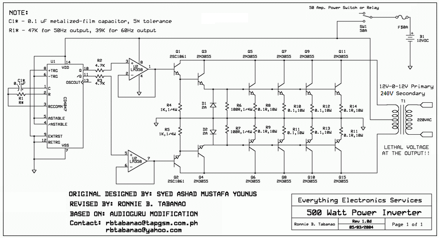 500Watts_Inverter-small.PNG
161.27 KB
Reply author: ovuriri
Replied on: Feb 13 2007 06:48:13 AM
Message:
Hello mr.audioguru,i am so happy!!!!!!i cant express my gratitude,but audioguru,what if i replace the 2n3055 bjt transistors with mosfet transistors,will it be okay?i love very much.have a lovely day...kenny
Reply author: audioguru
Replied on: Feb 13 2007 2:59:20 PM
Message:
This power inverter uses ordinary cheap transistors because Mosfets are not available everywhere. Mosfets are much better but the circuit for them must be completely different.
Reply author: ovuriri
Replied on: Feb 15 2007 12:37:56 PM
Message:
hello audioguru,i appreciate what u're saying,it making me understand why my circuit burns out.but audioguru,i prefer using mosfets transistors,i like to have the circuit using mosfets transistors.i love u,kenny.
Reply author: ovuriri
Replied on: Feb 16 2007 08:22:13 AM
Message:
hello audioguru,i also need to know why u cant simply use that circuit diaram,becos i found a mosfet that has same properties with the bjt transistor.ken
Reply author: audioguru
Replied on: Feb 16 2007 09:41:25 AM
Message:
A 2N3055 power transistor conducts 8A when its base-emitter voltage is typically 1.4V.
A power Mosfet is turned on when its gate-source voltage is 10V. A few "logic level" power Mosfets turn on when their gate-source voltage is 4V.
Mosfets switch much faster than transistors. Therefore a special circuit must be made so that one turns off first before the other one turns on. Or else both are turned on at the same time creating a dead short across the battery with hundreds of Amps of current.
Gary has many projects and one is a Mosfet square-wave inverter with a max power of 500w.
http://www3.telus.net/chemelec/Projects/Inverter/Mosfet-Inverter.htm
Reply author: ovuriri
Replied on: Feb 17 2007 10:22:37 AM
Message:
hello \,audioguru,are u very sure if that circuit works very well.i am using it for a project work and dont have enough money to play with.but do u still think the bjt transistors can work perfectly well without any problems.love u,ken.
Reply author: tim
Replied on: Feb 17 2007 11:17:20 AM
Message:
hi all, a resistor is 04.7ohm would 4.7 k ohm would this be the same.
Reply author: Binary 1011001101
Replied on: Feb 17 2007 11:41:52 AM
Message:
No, 4.7k ohm is 47000 ohms
0.47 ohm is less than 1 ohm
Reply author: tim
Replied on: Feb 17 2007 12:41:44 PM
Message:
can putting multiple resistors in paralelle to achive a value be done?
Reply author: audioguru
Replied on: Feb 17 2007 12:43:15 PM
Message:
The 500W inverter circuit that I posted has a square-wave output. Lots of things don't operate properly with a square-wave. The inverter is used in The Philippines to power fluorescent tube lights and multi-voltage TVs. it could also power heating appliances.
Reply author: cyclopsitis
Replied on: Feb 26 2007 08:27:58 AM
Message:
Tim, Yes you can put resistors in parallel to achive an uncomon value. The formula for parallel R is:
Rt = R1 X R2 / R1 + R2 = Rt
K
Reply author: tim
Replied on: Feb 27 2007 07:44:02 AM
Message:
does the same apply to putting resistors in series as well to get a value?
Reply author: cyclopsitis
Replied on: Feb 27 2007 10:19:04 AM
Message:
No, Resistors in series add their value for ex. one 10 ohm resistor in series with a 20 Ohm will equal 30ohms in the circuit. The same with inductors (coils). The Henry value adds together in series. Capacitors are the opposite. Caps in parallel add together the (uf rating) and in series they divide. You can probably find a write up on Google about it if you want to actually read it for yourself. I like studying this stuff I like knowing how things work so happy searching!
Ken
Reply author: omleje
Replied on: Mar 02 2007 08:52:13 AM
Message:
how long do the inverter works and can the circiut be made to produce 220v,5000w,50-60Hz?
Reply author: Aaron Cake
Replied on: Mar 02 2007 09:23:05 AM
Message:
quote:
Originally posted by omleje
how long do the inverter works and can the circiut be made to produce 220v,5000w,50-60Hz?
Please at least take a quick look over the topic before you post a question. This circuit does not work very well in most cases, and building an inverter of that size is completely impractical.
Reply author: CATWHISKER
Replied on: Mar 07 2007 12:12:24 AM
Message:
quote:
Originally posted by omleje
how long do the inverter works and can the circiut be made to produce 220v,5000w,50-60Hz?
JUST TAKE THIS AS A SUGGESTION.IF U HAVE TO BUILD AN INVETER, FIRST,BE SURE THAT IT IS PRACTICAL IN THE VERY SENSE!SECONDLY,CHOOSE A CIRUIT[DESIGN]THAT IS SURE TO BE 100% EFFICIENT.
THANKS, GOOD LUCK!
Reply author: audioguru
Replied on: Mar 07 2007 09:02:59 AM
Message:
It is impossible to make an inverter circuit that is 100% efficient. The transistors in an inverter pass many Amps of battery current and therefore get hot. The heat is wasted and reduces the efficiency.
If an inverter uses very good Mosfet transistors to switch the current then it would be about 90% efficient.
If it uses power transistors in a good design then it is about 80% efficient.
The inverter circuit on this site is about 40% efficient.
Reply author: cyclopsitis
Replied on: Mar 07 2007 5:51:07 PM
Message:
Not to mention that it takes a lot of engineers (elite, "smarter" then the normal person) a lot of thinking, prototyping, and research to get a circuit that is near 80% efficient! This is not something that the average electronics guru (not implying our audioguru on this site haha) can just put on paper and come up with it.
Why is this inverter thing so popular anyway? Even on other forum sites people always ask about inverters, wanting to build one!? WHY?
People, save your time and money. If you want a 1000W+ inverter buy one! Tripp-Lite makes really good ones for $300US.
K
Reply author: audioguru
Replied on: Mar 07 2007 7:03:29 PM
Message:
It is easy to make a fairly efficient square-wave inverter. The ouput transistors switch on and off so they hardly get a chance to get warm.
We are in Canada where electricity is nearly everywhere, is cheap and hardly ever fails. Some countries with billions of people don't have any electricity so they use inverters and car batteries to make their own.
In The Phillipines there are guys who pickup your dead battery and exchange it for a charged one, then they take the discharged one back to the big city for recharging.
In India there are rolling blackouts because they can't make enough electricity for everyone.
In Africa I don't know what they do.
Reply author: cyclopsitis
Replied on: Mar 09 2007 6:19:12 PM
Message:
Oh that makes sense, I'm a typical westerner (take things for granted).
Thanks for the info guru :D
K
Reply author: junkfunkydude
Replied on: Mar 22 2007 9:48:07 PM
Message:
Hi, this might have been mentioned earlier, but I'm too lazy to look it up.
I am attempting to use this inverter circuit to make a 120vdc to 12vdc converter. I was planning on inverting the 120vdc ,and converting it to 12vac by means of a transformer. This could then be rectified.
I ran into some trouble finding tantalum caps rated at 120V, any suggestions?
BTW, I don't care what frequency the inverter runs at. It could be 10hz or 10khz for all I care.
Reply author: audioguru
Replied on: Mar 23 2007 12:04:48 AM
Message:
This inverter circuit doesn't work.
Besides, its parts are rated for 12V, not 120V.
Where are you going to find 120VDC?
Reply author: junkfunkydude
Replied on: Mar 23 2007 4:36:39 PM
Message:
quote:
Originally posted by audioguru
Besides, its parts are rated for 12V, not 120V.
Where are you going to find 120VDC?
First of all, I know they are rated for 12v, not 120v, this is why I am searching for higher voltage rated components. I have been successful in locating replacements for all the components accept for the capacitors.
Second of all, if you really want to know the application for a 120VDC inverter circuit, here it is:
I recently purchased a 900MFD 125V electrolytic capacitor for the bargain price of $2.50 US. I did the math and found out that 900MFD at 120V is a capacity ruffly equal to 3aHr at 12V. This means that large capacitors at high voltages have higher capacity to weight ratio than any battery including Li-Ion cells. This astonishing capacity to weight ratio is only attainable at high voltages, so in order to make a virtual battery pack from a capacitor, voltage must be converted from the low voltage that would be used to charge the pack to high voltages before it goes into the capacitor, stored at high voltage, and then get converted back to a manageable voltage for use. If I can get this system to work with my 120V cap, I will attempt to build a virtual battery around a 400V capacitor.
This project is still on the drawing board, so if anyone has a suggestion on how to build an inverter based voltage converter, or any suggestions about how to do this efficiently without using inverters and a transformer, please let me know either in the forum, by e-mail, or by IM.
Reply author: audioguru
Replied on: Mar 23 2007 6:53:29 PM
Message:
A capacitor is not a battery. Its voltage begins to drop immediately when current is drawn and drops very quickly. 900uF at 125V is not a high capacity. Super capacitors are measured in FARADS. 10,000 times more capacity.
Charge your capacitor to 120VDC. Then it can supply 120mA for only 1 second. Then its voltage will be only 44V.
Invert the 120VDC down to 12V then it can supply 100mA for only 10 seconds when its voltage will drop to 4.4V.
Reply author: junkfunkydude
Replied on: Mar 24 2007 10:09:01 AM
Message:
You apparently misread the unit of measure of my capacitor, I is 900MF, not 900uf. This makes a huge difference. Also, this specif is project is just to "test the waters" if all works well, I'm thinking about getting a 2F 400v cap and doing the same thing.
Reply author: audioguru
Replied on: Mar 24 2007 11:55:34 AM
Message:
There is no such thing as a 900MF capacitor with a value of 900 million Farads.
Maybe it is "only" 900mF which is 900,000 uF.
Then it will supply 120mA for 1000 seconds which is 16.7 minutes and its voltage will drop from 120V to 44V.
Four AA size Ni-MH rechargable cells will provide the average power of 10W longer and their voltage won't drop as much.
Reply author: cyclopsitis
Replied on: Apr 05 2007 10:37:06 PM
Message:
Sometimes higher end caps like Mallory or ones made in the UK will say on them MFD I'm looking at one right now :D. Its the same as uF as far as I know just a differnet way of printing it.
K
Reply author: audioguru
Replied on: Apr 05 2007 11:21:00 PM
Message:
Capacitor manufacturers should learn the proper suffixes for their products:
1) M= million.
2) m= milli which is thousandths.
3) u= micro which is millionths.
Reply author: pebe
Replied on: Apr 06 2007 09:02:30 AM
Message:
As far back as I can remember, capacitor manufacturers in the UK like Plessey and Daly used MFD as an abbreviation for microfarad. Even a 100nF cap was refered to as 0.1MFD.
No doubt if they had still been in business they would have changed to the current convention, but unfortunately there are just about no UK owned electronics manufacturer left in the UK.
Reply author: sid_ric
Replied on: Apr 09 2007 10:51:01 AM
Message:
Hi
I live in africa and I am trying to build an inverter to make my nights bearable. I started with the schematic at
http://www.electronics-lab.com/projects/power/033/index.html but mid way through the project i found out from this thread that it is defective so I now building the one modified by the great audioguru (http://www.aaroncake.net/forum/uploaded/Audioguru/2007212205318_500Watts_Inverter-small.PNG.)
I have most of the components but the questions I have are
1- can I use ic LM324 in place of LM358 because the former are now lying idle on my bench and Iam finding it difficult to spend more.
2- CD4047 is hard to find here but i have a NE556 monostable multivibrator, is it possible to use this instead of the 4047. I would appreciate it if someone provided a schematic of how I could connect it to the setup
Reply author: audioguru
Replied on: Apr 09 2007 11:21:04 AM
Message:
quote:
Originally posted by sid_ric
I live in africa and I am trying to build an inverter to make my nights bearable.
No electricity in the jungle? How will you charge the big car battery that powers the inverter?
quote:
1- can I use ic LM324 in place of LM358 because the former are now lying idle on my bench and Iam finding it difficult to spend more.
An LM358 has the same opamps as in an LM324. An LM358 has two opamps and an LM324 has four opamps. Just change the pins numbers and disable the unused opamps.
[/quote]2- CD4047 is hard to find here but i have a NE556 monostable multivibrator, is it possible to use this instead of the 4047. I would appreciate it if someone provided a schematic of how I could connect it to the setup[/quote]
The CD4047 is perfect for making a square-wave inverter. It has a stable oscillator and a frequency divider that gives each side exactly the same time period. It has one output inverted from the other.
You can use many other oscillators in this simple inverter. A 556 could use one half as an oscillator and the other half as an inverter. The 556 doesn't need the dual opamp, use series 330 ohms output resistors to feed the transistors.
Reply author: sid_ric
Replied on: Apr 11 2007 12:11:46 PM
Message:
Hi
Thanx for the reply audio, we have electricity for a couple of hours during the day so I could use that time to charge.
Iam not an electronics guru and I don't really get what you mean by
"A 556 could use one half as an oscillator and the other half as an inverter. The 556 doesn't need the dual opamp, use series 330 ohms output resistors to feed the transistors."
I can atleast make the 556 as an oscillator but have no idea about the inverting part.
I was looking through some old equipment and I came across a part labeled HCF4027BE. I looked at its specs on the web and found out that it is a Dual JK flip-flop, is it possible to use this instead of CD4047
I would appreciate your response.
Reply author: audioguru
Replied on: Apr 11 2007 3:03:38 PM
Message:
2 hours per day is not long enough to charge a big car battery.
Half of a 556 is a 555. Make a 50Hz oscillator with one half of the 556. Then connect pin 2 to pin 6 together as an input(on a 555, look to see which pins on a 556) then it is an inverter.
A CD4027 is completely different to a CD4047.
Reply author: sid_ric
Replied on: Apr 13 2007 04:50:58 AM
Message:
Thanx alot for the advice, I have come up with a schematic, I have calculated it to oscillate at about 55hz
please have a look and correct me if anything is amiss.
http://www.geocities.com/sid_ric/556-oscillator-inverter.gif
Reply author: kivdenn
Replied on: Apr 13 2007 09:44:50 AM
Message:
Hi guys I would like to try some other FET power inverter circuit because Gary\s circuit kind of delays to turn on for the first 1/4 second.COuld we solve this or opt for other circuits
Reply author: audioguru
Replied on: Apr 13 2007 11:49:52 AM
Message:
Hi Sid,
Your 556 doesn't make a square-wave. It makes an assymetrical rectangular wave.
I modified it so its output charges and discharges the capacitor through the timing resistors equally.
I didn't check the frequency but maybe the pot I added will adjust to the correct frequency.
Hi Kivden,
You forgot to provide a link to Gary's inverter. I don't have time to search for it.
Download Attachment: 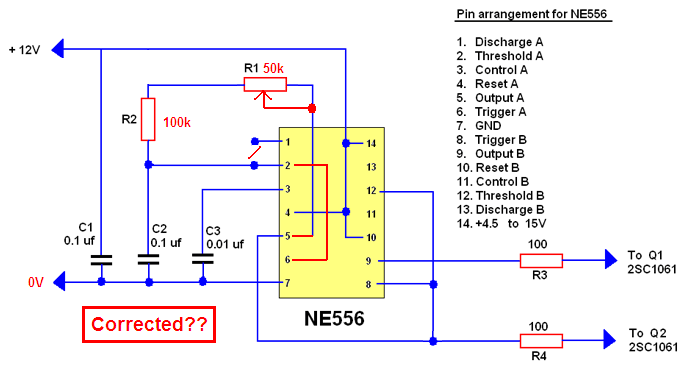 556 push-pull oscillator.PNG
35.72 KB
Reply author: Binary 1011001101
Replied on: Apr 13 2007 5:58:09 PM
Message:
Ive been trying to make this inverter on this page posted by audiougru, http://aaroncake.net/forum/topic.asp?TOPIC_ID=2996&whichpage=24 uses the CD4047 a/bisable mutivibrator IC, I also cannot find this so I used a 555 fed into a fip-flop driving transistors, The output is a low voltage of 18VAC, the input is 12.8V at 2 amps, transformer used was a 240v to 12-0-12. If I use the 0-12 windings it outputs a voltage so high it makes my multimeter spark and frazle inside!
Anyone know why? Also I have not used the op-amps and the small transistors to drive the 2N3055.
Thanks.
Reply author: audioguru
Replied on: Apr 13 2007 9:37:07 PM
Message:
Binary,
Yor oscillator/flip-flops have an input of 12.8VDC and the output is 18VAC? How?
If you feed 18VAC into the 12V winding of a 240V transformer then its output will be 18/12 x 240= 360VAC.
Please upload your schematic.
Reply author: Binary 1011001101
Replied on: Apr 14 2007 03:12:13 AM
Message:
I don't know why, its really weird.
Here is the schematitc http://i96.photobucket.com/albums/l178/binary10101/inverter.jpg
Ok screw what I said in my previous post, It gives out the HV when using the schematic above, I can even draw small sparks...
Reply author: audioguru
Replied on: Apr 14 2007 10:25:04 AM
Message:
Binary,
You saved your schematic as a fuzzy JPG file type instead of a very clear GIF or PNG file type. Why???
Then you uploaded it to PhotoBucket instead of here. Why???
I calculate the frequency of your 555 oscillator at 68Hz then the flip-flop divides it down to only 34Hz which is way too low. A capacitor marked "104" is 0.1uF.
The minimum input voltage for a 7812 regulator is 14.5V but you have only 12.8V. So it won't regulate and its output voltage is about only 10V.
You don't show which flip-flop IC you are using. It must be Cmos because TTL would fry with a 12V supply. The output current of Cmos with a 12V supply is only about 15mA which is way too low to drive 2N3055 transistors for power.
Your transformer is way too small for an inverter. Its max power is only 12V x 200mA= 2.4W. The output voltage would be very freaky without a load.
Reply author: Binary 1011001101
Replied on: Apr 14 2007 11:17:20 AM
Message:
I saved it as a JPG because express sch saves it as that and no other options, most of the time it is ok.
You can upload to here? I didn't know that, how do I do it
The flip flop I used was a SN74LS76AN. I also tried a darlington pair to drive the 3055, the low power BFY51 transistor hot VERY hot
Anyway, If I use your circuit without the op-amps and in place of the CD4047 there is a 555 and flip-flop giving the correct frequany would it work?
Reply author: fedfray
Replied on: Apr 23 2007 12:53:30 PM
Message:
hi audioguru.... u r an expert for electronic for me...can i ask something? for 500w inverter...can i paralel 6 trafo 10 A at 12 Vac for replacing 60 Ampere trafo 12/220 vac. i think it's more cheaper
Reply author: audioguru
Replied on: Apr 23 2007 4:01:16 PM
Message:
Hi Binary,
The flip-flop is TTL which needs a regulated 5V supply.Its output doesn't go to a high enough voltage for this circuit.
Hi Fedfray,
I don't think you sould connect transformers in parallel. They might not be exactly the same which would cause a high current to flow between them.
Reply author: Binary 1011001101
Replied on: Apr 23 2007 4:42:41 PM
Message:
Ok so would it work if I pass it through a high gain transistor to power to 3055s?
Reply author: audioguru
Replied on: Apr 23 2007 7:36:05 PM
Message:
Hi Binary,
Two 2N3055 transistors in an inverter would allow an output power of only about 80W.
The 2N3055 has a max 3V saturation voltage loss spec at 10A when its base current is 3.3A. The max base-emitter voltage is 1.5V at 4A and might be 2.5V at 8A. A TIP41 transistor to drive each 2N3055 has a max base-emitter voltage of about 1.5V at 3.3A and its base current would need to be at least 220mA. A 3rd driver transistor is needed to supply the 220mA and its base-emitter voltage is about 1V so the total voltage needed to drive the transistors is 2.5V + 1.5V + 1V= 5V. The max output voltage from a TTL flip-flop is only about 3.5V.
Reply author: Binary 1011001101
Replied on: Apr 24 2007 02:28:42 AM
Message:
Stupidly ive allready started making it wihtout knowing it will work.
So what if I put a opto-couple on it, not to isolate but to amplify the signal, a LED only needs about 3.5V and the other half I could make into a darlingtion pair...
Just more ideas,
Reply author: audioguru
Replied on: Apr 24 2007 08:04:22 AM
Message:
quote:
Originally posted by Binary 1011001101
So what if I put a opto-couple on it, not to isolate but to amplify the signal
No. Look at its datasheet. Many optical isolators don't amplify. 10mA in produces only 2mA out.
quote:
a LED only needs about 3.5V
No. Look at its datasheet. A white or blue LED is about 3.5V. The IR LED in an optical isolator is about only 1.2V.
In the 500W inverter that I fixed there are four 2N3055 transistors in parallel at the output on each side. They are driven by another 2N3055, which is driven by a medium power transistor, which is driven by an opamp, which is driven from a cmos oscillator operating with a 12V supply.
Reply author: snappyt
Replied on: Apr 25 2007 03:15:45 AM
Message:
Anyone help with this design for a load of 480 watts @ 240vac...what is the current draw on a 12 volt battery. Thanks.
Reply author: Aaron Cake
Replied on: Apr 25 2007 09:20:01 AM
Message:
quote:
Originally posted by snappyt
Anyone help with this design for a load of 480 watts @ 240vac...what is the current draw on a 12 volt battery. Thanks.
You will find several designs for suitable circuits in this thread already. Just read through it.
To make 480W @ 240VAC out of 12V, you need a minimum of 40A. But the inverter will not be 100% efficient so figure 20-50% on top of that.
Reply author: Sobat
Replied on: Apr 26 2007 01:24:29 AM
Message:
Hello Master Audioguru
I want to build inverter 12Vdc - 220Vac 500 watt, the circuit from
http://www.electro-tech-online.com/attachments/feedback-comments/11385-schematic-posting-problem-500watts_inverter-small.png?d=1170826950
modification by Audioguru, thanks to u'r idea
but i have problem to build it, i dont know what ampere i can use for the transformer. can i increase the wattage to 3000 watt, please show me how..
Thanks a lot
Reply author: cyclopsitis
Replied on: Apr 26 2007 01:56:12 AM
Message:
We can't see your link because we don't have a username and PW. If you read through some of this topic you'll find all the info you need for your prject.
Master cyclops haha
Reply author: audioguru
Replied on: Apr 26 2007 11:56:46 AM
Message:
3000W is way too much for an inverter. If you use only 12V then its battery current will be 300A!
You would need to have a large room full of batteries to power it for a short time. Then it will take 1 week the charge the batteries.
Its wiring must be huge and it would need 48 output transistors and many driver transistors.
Its transformer would cost a fortune.
Reply author: snappyt
Replied on: Apr 28 2007 5:58:40 PM
Message:
Thanks for the help....Aaron Cake
Reply author: Sobat
Replied on: May 02 2007 08:40:11 AM
Message:
Hello Master AudioGuru
It's me again, this time i want to build inverter 12 volt to 120 volt, but i can't find HEP 154 silicon dioda in my country, can i change with another diode, what tipe diode can i use for this circuit.
http://www.aaroncake.net/circuits/inverter.asp
Thank you Very much
Reply author: audioguru
Replied on: May 02 2007 09:32:00 AM
Message:
This inverter circuit is too simple to work properly. Its output might be only 25W. Its capacitors are backwards which causes them to explode. Its transistors don't have nearly enough base current and are constantly having reverse breakdown.
Read about it in this long thread.
Reply author: ogun4ever
Replied on: May 04 2007 09:54:05 AM
Message:
pls i need dc to ac inverter of 20w
Reply author: audioguru
Replied on: May 04 2007 12:15:35 PM
Message:
20W is almost nothing.
This circuit should work.
Download Attachment:  100W inverter.GIF
15.87 KB
Reply author: tmk3a014
Replied on: May 10 2007 08:33:40 AM
Message:
Hi I'm sugeng I have some question and i hope some of you can help me to solve my problem,
I want to make inverter that can change 12VDC to 220VAC, please send me the diagram and tge component list. I also want to make an automatic battery charger for 12V battrey but my source is from solar cell please send me the diagram and the component list.
Thank you, my email is mulyadi_sugeng@yahoo.co.id
I hope i can have the diagram and the component list soon.
Reply author: Aaron Cake
Replied on: May 10 2007 09:05:51 AM
Message:
quote:
Originally posted by tmk3a014
Hi I'm sugeng I have some question and i hope some of you can help me to solve my problem,
I want to make inverter that can change 12VDC to 220VAC, please send me the diagram and tge component list.
This has been answered several times before in this thread. Just use the appropriate transformer.
Reply author: mrenjan
Replied on: May 11 2007 09:11:19 AM
Message:
One Question to AudioGuru.. Is there any advantage of using 2N3055 instead of Mosfet's like IRF540 directly tied to CD 4047. We dont even need the OP-amps since Mosfet requires only less Drive current. Probably the only other change required is in the Transformer side (9-0-9 instead of 12-0-12). I thought the efficiancy of Mosfet is much higher than Transistor since leakage current is less. Not sure whether i am wrong.
Reply author: audioguru
Replied on: May 11 2007 10:08:38 AM
Message:
quote:
Originally posted by mrenjan
One Question to AudioGuru.. Is there any advantage of using 2N3055 instead of Mosfet's like IRF540 directly tied to CD 4047. We dont even need the OP-amps since Mosfet requires only less Drive current. Probably the only other change required is in the Transformer side (9-0-9 instead of 12-0-12). I thought the efficiancy of Mosfet is much higher than Transistor since leakage current is less. Not sure whether i am wrong.
2N3055 transistors were used in the 100W and 500W inverter because the circuit is very old and 2N3055 transistors atre available in countries that don't have Mosfets. Mosfets are much better.
The IRF540 Mosfet is also getting pretty old since much better Mosfets are available now.
The CD4047 can directly drive two Mosfets in an inverter and the output power depends on their current rating and the size of the heatsink. Cheap Chinese inverters use Mosfets.
Efficiency is determined by how much power is wasted as heat in the transistors when they conduct, not leakage current.
A 2N3055 transistor has a max saturation voltage of 3V at a collector current of 10A and a huge base current of 3.3A. That is 35W of heat for a 100W inverter.
An IRF540 Mosfet has a max saturation voltage of 0.44V at 10A so wastes only 4.4W in a 100W inverter. Better Mosfets would operate cooler and therefore the efficiency would be higher.
If you use a 9-0-9 transformer with Mosfets then with a fully charged battery at 13.8v the output voltage will be 170VAC instead of 115VAC or will be 341VAC instead of 230VAC.
If you use a 12-0-12 transformer with Mosfets and a fully charged battery then the output will be 128VAC instead of 115VAC and will be 256VAC instead of 230VAC.
Reply author: mrenjan
Replied on: May 14 2007 12:17:56 AM
Message:
Thank you Audioguru for your time.. This is lot of good information. Can you please tell me a better Mosfet for such application ?
I thought there was a 3 V (Drain source)drop when using Mosfet (IRF 540).. So the battery voltage for 13.8 should be taken as 10.8 when doing calculation using Mosfet. Also if we use a ordinary 12-0-12 or 9-0-9 mains transformer,the losses associated also will be high since Primary and secondary is now in the reverse order. Please clarify.
Reply author: audioguru
Replied on: May 14 2007 4:24:03 PM
Message:
The old IRF540 Mosfet has a drain to source max resistance of 0.044 ohms when it has at least 10V on its gatwe and it is cool.
Then its voltage drop is 0.44V at 10A and is 2.2V at 50A. 50A x 2.2V would make 110W of heat which would increase its resistance as shown on the graph in its datasheet.
There are hundreds of newer and better Mosfets. An IRF3711Z has an on-resistance of only 0.006 ohms. At 50A its voltage drop is only 0.3V.
Transformers have a max power rating. Do not allow the inverter and its load to exceed the max power rating then the loss is very low.
Reply author: mrenjan
Replied on: May 14 2007 11:17:22 PM
Message:
Thank you Audioguru..
Reply author: sunil_223
Replied on: May 17 2007 09:30:27 AM
Message:
hi audioguru i have tried to make the inverter but it didnt work.
i am using 12/220v transformer.
68uf 16v capictor{tantlum}.
4007 diodes.
2n 3055 transistors.
180ohms 1 watt and 10ohms 5 watt resistor
but it didnt work.
only the transistors r heating up and no output is there.
please help me out.
can u tell me were i am wrong.
plz send me the schematic diagram of inverter if u have made any changes in it.
thanx
Reply author: audioguru
Replied on: May 17 2007 11:32:31 AM
Message:
Hi Sunil,
The transistors in the simple inverter have avalanche breakdown if the supply voltage is more than 8V.
The capacitors are shown connected backwards.
The circuit doesn't provide enough base current for the transistors to make much power.
It has too many things wrong for me to make changes to it. It is too simple to work properly.
Reply author: sunil_223
Replied on: May 18 2007 05:49:56 AM
Message:
thanx for ur reply
so audioguru have u rectified the problem?what is it can u tell me ?is it possible to make such simple inverter by making some changes in it?
waiting for reply
Reply author: sunil_223
Replied on: May 18 2007 12:17:09 PM
Message:
hello audioguru
the schematic diagram for inverter on this page for 100watts is working properly?will this circuit function properly?
and what about that 500watts?shall i start making any one of them?
both r right or not?
plz reply
Reply author: audioguru
Replied on: May 18 2007 4:22:48 PM
Message:
The 100W and 500W inverters have a square-wave output if your load doesn't mind.
I don't know if anybody has made the 100W one, but the 500W one works fine. The 100W one is the same but is smaller so it should also work fine.
Their capacitors are not connected backwards.
Their transistors do not have avalanche breakdown.
Their transistors have plenty of base current for a high power output.
Reply author: sunil_223
Replied on: May 19 2007 01:58:49 AM
Message:
thanks audioguru
first i will try for 100w if it works then i will go for 500w
i want to know that what is the watts for R1,R2 and R3
and what is the volts for .1uF cap and power switch or relay?
i mean to say resistor R1 is 47k ohms but how many watts?
same for cap and relay.
relay is necessary for this circuit?
can u tell me what is 12-0-12v transformer?
i had purchased it.
Reply author: audioguru
Replied on: May 19 2007 1:32:35 PM
Message:
quote:
Originally posted by sunil_223
i want to know that what is the watts for R1,R2 and R3
Very, very low. Calculate it:
The max voltage across R1 is about 6.5V. Then its max power is only 0.9mW. The power in R2 and R3 is much lower. So any resistor power rating will be fine.
quote:
and what is the volts for .1uF cap
It gets only 6.5V across it. I would use a metalized poly 5% capacitor. Their minimum voltage rating is 50V or 63V which is fine.
quote:
and what is the volts for power switch?
It gets a max voltage of about 14V so any voltage rating will be fine.
quote:
relay is necessary for this circuit?
There is no relay in the circuit. A high current switch is shown.
quote:
can u tell me what is 12-0-12v transformer?
It is 24V with a center-tap and it is needed if a 12V car battery powers the inverter. A transformer with two 12V windings can also be used if the windings are connected together properly.
quote:
i had purchased it.
I hope it has a power rating that is high enough.
Reply author: sunil_223
Replied on: May 20 2007 02:40:59 AM
Message:
thanx audioguru
Reply author: sunil_223
Replied on: May 20 2007 03:30:55 AM
Message:
audioguru can u tell me that what is the effect if we use 12v but with different amps.I mean to say that if i am using 12v battery with 2.3amps/h and if i replace it with 1.2amps/h.
does it effect watts or volts or nothing will happen?
and what if i change the volt from 12v to 24v?what will be the effect?
Reply author: audioguru
Replied on: May 20 2007 9:56:34 PM
Message:
A 100W inverter need a battery current of 10A. A 500w inverter needs a battery current of 50A.
A car battery, not a tiny little battery like you have. A car battery is rated at 70Ah to 100Ah.
Reply author: sunil_223
Replied on: May 25 2007 07:42:57 AM
Message:
hi audioguru can u tell me approximately how many solar cells i will be required to get 12v 5amps.
Reply author: audioguru
Replied on: May 25 2007 11:30:00 AM
Message:
quote:
Originally posted by sunil_223
hi audioguru can u tell me approximately how many solar cells i will be required to get 12v 5amps.
I don't know the size and the ratings for your solar cells.
I bought a 12V/150mA solar panel. I don't live on the equator so its output current at noon when it points directly at the sun outside is only 120mA. Before or after noon its output current is much less. If it is not aimed directly at the sun then its output current is also much less. Indoors with it aimed directly at the sun at noon its current is only 50mA.
Your 12V/5A solar panel will have an average current of about 2A for 8 hours per day. Not enough power for an inverter at night.
Reply author: Aaron Cake
Replied on: May 27 2007 10:21:30 AM
Message:
quote:
Originally posted by sunil_223
hi audioguru can u tell me approximately how many solar cells i will be required to get 12v 5amps.
Please keep all other topics out of this thread. This thread is for inverter discussion only. Thanks.
Reply author: intelboard
Replied on: May 30 2007 12:02:04 PM
Message:
Is their any method to step-up AC voltage without a transformer ? (Please Reply soon)
Reply author: audioguru
Replied on: May 30 2007 7:49:27 PM
Message:
A 555 oscillator can drive a voltage doubler. tripler or quadrupler to increase the voltage but the current is reduced.
An ICL7660 IC doubles the voltage or makes a negative voltage but its output current is pretty low.
Reply author: intelboard
Replied on: May 31 2007 09:19:53 AM
Message:
Can any transistor do that thing without decreasing the current
Reply author: audioguru
Replied on: May 31 2007 10:34:38 AM
Message:
Make a transistor oscillator then add a voltage multiplier circuit to it.
Power out must equal power in so if the voltage is doubled then the current output is halved.
Reply author: intelboard
Replied on: May 31 2007 11:21:48 AM
Message:
Can you show me the schematic of both the circuit - with 555 osc and transistor.
Reply author: Aaron Cake
Replied on: Jun 01 2007 09:18:49 AM
Message:
quote:
Originally posted by intelboard
Can you show me the schematic of both the circuit - with 555 osc and transistor.
Please create another topic and discuss the circuit there. This topic is for discussion of the 12V to 120V inverter and related circuits only.
Reply author: intelboard
Replied on: Jun 01 2007 11:01:13 AM
Message:
This circuit is also related to 12v to 230v inverter only.
Reply author: tim
Replied on: Jul 04 2007 3:40:56 PM
Message:
is there some kind of formula as to putting mosfet transistors together to run either an inverter or a dc motor controller, i mean the control for the gates on the mosfets.
Reply author: audioguru
Replied on: Jul 04 2007 4:10:04 PM
Message:
Most Mosfets turn on when their gate is 10V or a little more higher than their source voltage. They turn off when their gate voltage is the same as their source voltage.
For a low frequency square-wave inverter two Mosfets can be driven by a CD4047 Cmos oscillator.
For high frequency pulse-width-modulation for motor speed control then a Mosfet driver IC should be used to quickly charge and discharge the high gate capacitance of the Mosfets, and to provide dead-time so that one Mosfet is off when the other turns on.
Reply author: mansoorkkl
Replied on: Jul 22 2007 09:08:17 AM
Message:
[quote]Originally posted by essien
pls i want a circuit diagram for a 2000 W inverter[12vdc to 230/240vac]
Reply author: mansoorkkl
Replied on: Jul 22 2007 09:21:37 AM
Message:
pls give me a simple low cost circuit diagram for a 2000 W inverter
[12vdc to 220/230/240vac]
Reply author: audioguru
Replied on: Jul 22 2007 09:22:34 AM
Message:
A 2000W square-wave inverter will dissipate about 400W of heat.
It will draw 200A continuously from a 12V battery at full load which will cause it to explode.
You will need many output transistors, a huge and expensive custom-made transformer and a bus full of car batteries that will take a week to charge.
Rediculous.
Some 2000W inverters operate from 48VDC then four car batteries in series last a few hours.
Reply author: mansoorkkl
Replied on: Jul 22 2007 09:28:19 AM
Message:
pls give me a simple low cost circuit diagram for a 1000 W inverter
[12vdc to 220/230/240vac]
Reply author: Aaron Cake
Replied on: Jul 22 2007 10:09:00 AM
Message:
quote:
Originally posted by mansoorkkl
pls give me a simple low cost circuit diagram for a 1000 W inverter
[12vdc to 220/230/240vac]
Please actually read the topic before you post. This has been covered several times.
There will be no low cost circuit. Designing a 1KW inverter is nontrivial. The drive silicone will be very expensive and the transformer very large.
Reply author: tim
Replied on: Jul 25 2007 2:57:27 PM
Message:
well there is 12,000 watt inverters on ebay for 600.00 all you got to do is get a few 8-D batterys and there you go.
Reply author: srimovva
Replied on: Jul 28 2007 09:05:55 AM
Message:
quote:
Originally posted by phoenix
HEY! Thanks 4 the advice...
T-boss
Reply author: newjazzy2005
Replied on: Jul 28 2007 12:36:15 PM
Message:
please i need an inverter circuit schmatic diagram that wiil give 220vac voitage and it input will be 12 or 24 vdc and wiil be able to last for 2 hour thanks
Reply author: audioguru
Replied on: Jul 28 2007 4:17:50 PM
Message:
Any inverter will last for 2 hours or more if its battery is big and its load current is low.
I can buy a amall 75W inverter for a low price. A car battery will last 10 hours powering it if it has a 75W load.
Reply author: mansoorkkl
Replied on: Jul 31 2007 12:15:41 PM
Message:
I need 12VDC To 220VAC 1000W To 1500W Invertor Pls Send Me Diagram And All Detail
Reply author: audioguru
Replied on: Jul 31 2007 1:47:07 PM
Message:
The current in the output transistors and from the battery will be 150A if the load on a 12V inverter is 1500W. A big car battery will explode. The transformer will be huge and will cost a fortune. Many transistirs will be needed.
Rediculous.
Reply author: Aaron Cake
Replied on: Aug 02 2007 09:56:11 AM
Message:
I think it may be time to close this topic? Every possible inverter question has been asked and answered multiple times.
Reply author: audioguru
Replied on: Aug 02 2007 09:59:37 AM
Message:
Most questions about high power inverters are coming from countries without electricity.
Where do they charge the battery?
Reply author: Aaron Cake
Replied on: Aug 04 2007 10:36:39 AM
Message:
My guess would be wind, solar, treadmill, etc. ![]()
But I wonder where they get the parts?
Reply author: tim
Replied on: Aug 04 2007 4:25:09 PM
Message:
well if they got a computer to ask what they ask then they can get parts mailed to them i would imagine, lol lol......
Reply author: audioguru
Replied on: Aug 04 2007 4:41:21 PM
Message:
They don't have any money or credit cards and they probably don't have a postal system.
Reply author: cisco229
Replied on: Aug 04 2007 6:38:02 PM
Message:
Hello, How are you, i wanted to build a inverter, but I am just a newbie, im tired of trying that aaroncake one, dont work, i want something simple & easy to build, even if its only 60 watts if you can help contact me At Cisco229@comcast.net, i just need to see how they work, in the most basic form then I can Do the math and make it better, thank you very much
Reply author: audioguru
Replied on: Aug 05 2007 1:10:49 PM
Message:
Make an oscillator from a CD4047 IC, a resistor and capacitor. The IC has two outputs which are out-of-phase and they are perfect to drive two power Mosfets that drive a center-tapped stepup transformer.
Then you will have a very simple square-wave inverter.
Reply author: mrgone
Replied on: Aug 11 2007 8:01:36 PM
Message:
How is the power (wattage) calculated? I was surprized that you need a 16 Amp Xformer to achieve only 300 watts. I know there is an efficiency consideration but the way I see it is 15 Amps X (120 volts X rms or .707) = 1272 watts. If we divide 300 by 1272 we get only 23 % efficiency of the xformer. Does this sound correct?
Reply author: audioguru
Replied on: Aug 11 2007 11:15:30 PM
Message:
The square-wave inverter circuit heats with about 20% of its max power output. So a 300W inverter uses 360W from the battery. The battery current flows through the low voltage winding of the transformer and through the output transistors and is 360W/12V= 30A.
Reply author: mrgone
Replied on: Aug 12 2007 1:31:48 PM
Message:
quote:
Originally posted by audioguru
The square-wave inverter circuit heats with about 20% of its max power output. So a 300W inverter uses 360W from the battery. The battery current flows through the low voltage winding of the transformer and through the output transistors and is 360W/12V= 30A.
OK, Would it be more efficient if you shape the wave first? You could get some reasonable facsimile of a sine wave using an RC filter arangement. Also what you were talking about above. I do the same thing with 74HC04s (inverters). Make an oscillator with it and feed the output to the remaining inverters to get the two phases.
Reply author: audioguru
Replied on: Aug 12 2007 2:05:23 PM
Message:
If you feed a sine-wave shaped waveform into power transistors or power Mosfets then they spend plenty of time with a high current and a voltage across them. Then their power dissipation (heating) is the current times the voltage. It will be a tremendous amount of heat to get rid of and it makes a tremendous waste of battery power.
An efficient sine-wave inverter switches the transistors on and off at a high frequency. Then pulse-width-modulation changes the width of the pulses so the average current in the transformer is a sine-wave.
The transistors remain fairly cool because when they have a high current then their voltage is nearly zero and when they have voltage then their current is zero.
Reply author: newjazzy2005
Replied on: Aug 20 2007 12:19:59 PM
Message:
can any one help me with i.c inverter cuicuit schmatic diagram
Reply author: audioguru
Replied on: Aug 20 2007 12:48:22 PM
Message:
What help do you need? Attach your schematic.
Reply author: mrgone
Replied on: Aug 20 2007 5:01:13 PM
Message:
quote:
Originally posted by newjazzy2005
can any one help me with i.c inverter cuicuit schmatic diagram
Do you mean this one? I posted this in another thread.
Download Attachment:
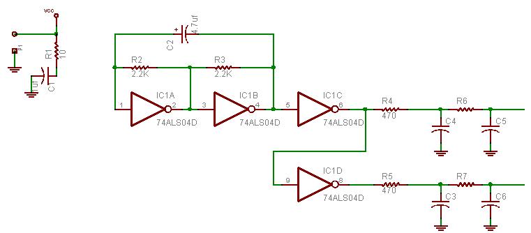 Inverter1.JPG
25.26 KB
Reply author: kivdenn
Replied on: Sep 27 2007 08:16:03 AM
Message:
What wave form does this one produce?, Does it have a low voltage shutdown? Which pin goes to Vcc and the ground and to which pins are the mosfet chanels connected? SOme capacitor valus are not shown like c3 to c6 Thanks
Dennis
Reply author: audioguru
Replied on: Sep 27 2007 10:35:00 AM
Message:
Its outputs are filtered into almost a sinewave.
It uses an old fashioned TTL logic inverter IC that needs a regulated 5V supply.
It doesn't have low voltage shutdown. Its output voltage isn't high enough to drive Mosfets.
If you try to make a sine-wave inverter using a sine-wave input into a Mosfet amplifier then they will get extremely hot and waste a lot of battery power.
A sine-wave inverter switches its Mosfets completely on and off so they don't get too hot and so they don't waste a lot of battery power. They are switched at a high frequency and pulse-width-modulation is used to make a stepped sine-wave that is filtered into a good sine-wave.
Reply author: Ruben
Replied on: Oct 01 2007 8:07:42 PM
Message:
quote:
Originally posted by ZETABOY
Any have a plan plans for build an Iverter of 5000 watts. i want build a inverter of 5000watts or more bigger
Reply author: audioguru
Replied on: Oct 01 2007 9:24:39 PM
Message:
Where are you going to get 6000W of power to power the 5000W inverter? 8 huge car batteries would last only 1 hour. 32 huge car batteries would last only 5 hours.
The transformer would cost a fortune.
Reply author: khaled125
Replied on: Oct 09 2007 3:42:55 PM
Message:
hello every body..im new 2 electronics.. am going 2 use the transformer with 220V as for primary(input) and 12V as for secondary(output). how much wattage it will produce and is it right to use 12v dc to the input with that transformer?
thanks alot 2 all of u
Reply author: khaled125
Replied on: Oct 09 2007 3:45:33 PM
Message:
i forgot to tell that my transformer is 10A.
Reply author: Binary 1011001101
Replied on: Oct 09 2007 3:48:42 PM
Message:
You are making an inverter, right? If so you will need to make the 12v as the input and 220V as output.
I need to know how many amps you are feeding in or better, how many amps it is giving out. Remember to work out the wattage is volts times amps
You can't use DC on a transformer, it will be a direct short...
Reply author: khaled125
Replied on: Oct 09 2007 4:00:24 PM
Message:
thank u 4 ur reply..i want 2 explain that the transformer is 0220/012 /10A/150VA/it weighs about 3kiloand 40 grams
Reply author: khaled125
Replied on: Oct 09 2007 4:05:47 PM
Message:
the transformer is center-tapless transformer.
Reply author: khaled125
Replied on: Oct 09 2007 4:19:03 PM
Message:
![]()
Reply author: Binary 1011001101
Replied on: Oct 09 2007 5:20:25 PM
Message:
Ok you will need a full bridge to make that into a inverter since it does not have a center-tap...
And for wattage I think it would be about 80-90 watts
Reply author: khaled125
Replied on: Oct 09 2007 6:31:05 PM
Message:
ok thank u ..but what will be the result if i use it with this circuit plz
Download Attachment:  ckt30_1.gif
8.77 KB
Reply author: audioguru
Replied on: Oct 09 2007 11:25:31 PM
Message:
You found the schematic of an inverter from a Japanese guy.
Then why don't you read the entire project including his test of it?
http://hobby_elec.piclist.com/e_ckt30.htm
Its output voltage is 10% high without a load and is 10% low with a load of only 140W.
Then your 220V will be 242V without a load and will be 198V with a 140W load. Pretty bad voltage regulation.
Download Attachment: 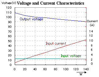 Japanese inverter.PNG
7.23 KB
Reply author: khaled125
Replied on: Oct 09 2007 11:41:38 PM
Message:
thanks a lot...but what should i do now change the transformer or what
thank u in advance
Reply author: audioguru
Replied on: Oct 10 2007 10:46:06 AM
Message:
Use a more powerful center-tapped transformer with only two more powerful Mosfets.
Reply author: khaled125
Replied on: Oct 10 2007 1:02:26 PM
Message:
thanks for ur advice
Reply author: khaled125
Replied on: Oct 10 2007 4:56:23 PM
Message:
Can we use a circuit before the battery in order 2 charge through the voltage 220V in other words inverting circuit from 220 to 12 V, and ofcourse with a suitable Amps??
Reply author: audioguru
Replied on: Oct 10 2007 5:33:42 PM
Message:
You can use the transformer from an inverter in a battery charger if you disconnect most of the inverter's circuit from the transformer.
Reply author: khaled125
Replied on: Oct 10 2007 6:01:38 PM
Message:
Thank u for answering me here in our country there is an inverter sold at about 200$ it is made locally the input is 12V and the output is 220V and 700 watt.can u guess the specifications of the transformer of it plz? thanks once more.
Reply author: khaled125
Replied on: Oct 10 2007 6:05:38 PM
Message:
sorry..I read the word "charger" on that inverter case what is meant by "charger" here.Sorry but as u may no that am new and this is my first try to make an inverter by my slef so tolrate me if asked u much.
Reply author: audioguru
Replied on: Oct 10 2007 8:48:40 PM
Message:
quote:
Originally posted by khaled125
here in our country there is an inverter sold at about 200$ it is made locally the input is 12V and the output is 220V and 700 watt.can u guess the specifications of the transformer of it plz?
The 700W inverter gets warm or hot because it has some losses. The wasted heat is probably about 100W so the 12V car battery, the Mosfets and the 12V winding on the transformer must be rated for 800W/12V= 66.7A.
Reply author: khaled125
Replied on: Oct 11 2007 4:50:18 PM
Message:
last question plz I am thinking of something but i dont no if it is right just thinking of it which it is that i want 2 make the circuit which converts the 6V dc into 12V dc and then connect it to the inverter since the inverter needs 12V. Will it work?if it will, can u tell me what is the specifications of the 6V battery should be(i dont no if am right or fool in such a thing)coz at the time being i cant get a battery of a car coz the cross-points are blocked and they dont allow any thing to pass these days.This is y am thinking of such a thing.and i would like to thank u much for not ignoring my question .
Reply author: audioguru
Replied on: Oct 11 2007 5:45:13 PM
Message:
The 6V to 12V circuit has an output of only 0.8A at 12V. The 700W inverter needs 66.7A at 12V.
Where is the missing 65.9A going to come from??
Why not make a 700W inverter with a 6VDC input and a 220VAC output?
Use a huge 6V battery that can supply 133.3A.
Use a 220V to 12V/134A center-tapped transformer (800W).
Use many logic-level Mosfets (they turn on with a gate voltage of only 5V) to switch the 133.3A from the battery to the transformer.
Reply author: khaled125
Replied on: Oct 11 2007 7:07:42 PM
Message:
Thanks a lot
Reply author: Aaron Cake
Replied on: Oct 14 2007 10:32:16 AM
Message:
Can we please keep this topic actually on topic? ![]() With over 100,000 reads it's probably the most popular and informative on this forum and I would hate to have to delete large chunks out of it to clean it up.
With over 100,000 reads it's probably the most popular and informative on this forum and I would hate to have to delete large chunks out of it to clean it up.
That said, maybe it is time to just lock it since all new questions seem to be a complete repeat of previous questions.
Reply author: khaled125
Replied on: Oct 14 2007 11:39:21 AM
Message:
http://www.sis.gov.eg/En/Default.htm
Reply author: audioguru
Replied on: Oct 14 2007 1:12:23 PM
Message:
The Gaza strip is the Middle-East jail.
Are you talking about using an inverter with a 700W load and powering it with a 100Ah car battery?
The battery current will be about 67A and the battery charge will last only about an hour.
The battery might boil dry before its charge runs out.
If the 700W inverter is very efficient then if it has a 100W load a 100Ah battery charge will last for 10 hours.
Where are you going to find the schematic and parts list for a 700W inverter that works?
Reply author: khaled125
Replied on: Oct 14 2007 2:47:15 PM
Message:
No am not talking about 700W inverter.talking about 120W inverter using a car battery 60A.
Reply author: audioguru
Replied on: Oct 14 2007 6:37:56 PM
Message:
Where is the schematic of the 120W inverter?
A 120W inverter will draw about 12A from a 12V battery when it has a 120W load.
The charge on a little 60Ah battery will last about 3 or 4 hours.
A little 60Ah battery is used on a little motor-bike. You should use a real powerful battery made for a big American car.
Reply author: steamingt
Replied on: Oct 15 2007 06:21:51 AM
Message:
Do you people think the stuffs will work if I try it?
I hate wasting time on what surppose to be ever ready circuit.
Reply author: audioguru
Replied on: Oct 15 2007 09:58:12 AM
Message:
What "stuffs" are you talking about?
Some circuits work because they are designed properly and other circuits don't work (guess why not).
Reply author: willhse
Replied on: Oct 28 2007 6:52:48 PM
Message:
its better use a 555. use 3 pin to 33 ohm to B, use 3 pin to 1000 ohm to pnp thans. C on pnp to 50 ohm to other trans. forget those 68's. If I can find how to put schematic up....
Reply author: pebe
Replied on: Oct 28 2007 7:16:05 PM
Message:
Willhse, can you re-phrase that to make sense?
Reply author: audioguru
Replied on: Oct 28 2007 9:28:04 PM
Message:
A simple inverter uses two Mosfets or power transistors in push-pull driving a center-tapped transformer.
The Mosfets have a low drive current so they can be driven from a Cmos oscillator IC that has opposite outputs.
The transistors have a high drive current so they need driver transistors to boost their input current then they can be driven from a Cmos IC that has opposite outputs.
The CD4047 Cmos IC is an oscillator with opposite outputs. A 555 is not.
Reply author: meerojak
Replied on: Oct 28 2007 11:09:58 PM
Message:
Before this thread comes to an end, i read all replies from page 1 to the last page. whew! At least i got ideas. But i need an answer to this querry.
I need to light up a 10W, 0.230A fluorescent tube with a small 12v, 7.0 Ah lead acid battery. Does the schematic circuit modified by audioguru works in this just use a suitable transformer? What would the spec of that transformer would be? I used a DC choke 12v for 20W fluorescent tube, and it overheat when my load is only 10W. When I use a DC choke for 8W, my 10W fluorescent tube lights dimly. Any suggestions? thank you very much.
anthony
Reply author: audioguru
Replied on: Oct 28 2007 11:57:37 PM
Message:
A 20W fluorescent tube needs a ballast for a 20W fluorecent tube. The ballast operates from the mains voltage and provides a high voltage to start the tube to light and limits the current.
Compact fluorescent light bulbs have an electronic ballast that steps up the voltage and provides a high voltage to start the tube to light and limits the current.
An inverter operating from 12V can supply mains voltage for either type of fluorescent light's ballast.
I have seen many inverters that use a center-tapped transformer.
I have never seen an inverter that uses a DC choke.
You said you tried a circuit with DC chokes that didn't work. Then please attach the schematic of the circuit so we can see what is wrong.
Reply author: Binary 1011001101
Replied on: Nov 01 2007 3:21:26 PM
Message:
I can't seem to find any CCFL inverter schematics on the net so I can only give you this advise:
CCFL dirvers are quite complex, the tubes require a quick spike to get the tube ionized, once it is ionized it is a low resistance so current limiting is needed and a constant high voltage to keep it ionized...
There may be a way of driving it "hard" that I don't know of...
Also, whats with the massive space below your message?
Reply author: sanctajoe
Replied on: Nov 02 2007 6:21:22 PM
Message:
h'llo Audioguru,can I uz another op-amp like PAO4(200w 20A) to boost the current feed-in to the driver transistor stage ?
Reply author: audioguru
Replied on: Nov 02 2007 8:05:58 PM
Message:
The PA-04 has many transistors and Mosfets and is not nedded for an inverter.
A 500W square-wave inverter just needs 2 power Mosfets driving a center-tapped transformer and driven from a CD4047 oscillator.
Reply author: lessthanchris1
Replied on: Dec 02 2007 01:15:30 AM
Message:
Ok, I've made it through 20 pages, and I give up. Do you have a working 12V to 120V inverter plan in the 500W-1000W range?
Thanks
Reply author: tim
Replied on: Dec 02 2007 10:51:03 AM
Message:
i think we all would agree by now that its much easier to just go out and buy a 12 volt 1000 watt inverter .
Reply author: audioguru
Replied on: Dec 02 2007 12:18:01 PM
Message:
A Chinese 12V 1000W inverter is probably rated in Whats. It is probably 1000Watts for less than 30 seconds or 500Watts all day long.
A simple 500W to 1000W inverter can be made with a CD4047 ocillator driving two Mosfets into a center-tapped transformer. The output will be square-waves but many electronic items won't work from it.
Reply author: furquan
Replied on: Dec 17 2007 11:35:27 AM
Message:
please explain the working of 9 volt dc to 120 volt ac inverter
Reply author: audioguru
Replied on: Dec 17 2007 11:43:22 AM
Message:
quote:
Originally posted by furquan
please explain the working of 9 volt dc to 120 volt ac inverter
A 50Hz or 60Hz oscillator drives power transistors or power Mosfets to obtain high current at 50Hz or 60Hz. They drive a stepup transformer.
The output of this very simple circuit is square waves which are different to the sine-waves in the mains.
Reply author: tich
Replied on: Jan 11 2008 10:43:57 AM
Message:
guys if i put a sine wave oscillator in place of the cd4047 i should be able to get a 500W sine wave oscillator right????
Reply author: audioguru
Replied on: Jan 11 2008 4:11:10 PM
Message:
quote:
Originally posted by tich
guys if i put a sine wave oscillator in place of the cd4047 i should be able to get a 500W sine wave oscillator right????
Nope.
You will get 500W of heat for a moment then the output transistors will melt.
You don't convert a linear power amplifier into an inverter. It wastes as much power as its output. The wasted power makes a lot of heat.
A sine-wave inverter switches its outputs on and off at a high frequency. Then when switched on there is no voltage across the power Mosfets but the current is high. No voltage then no waste as heat. They switch quickly and the voltage of the many steps of the sine-wave is made by controlling the duty-cycle of the switching waveform using pulse-width-modulation.
Class-D power amplifiers work the same way and are very powerful without a lot of wasted heat.
Reply author: tich
Replied on: Jan 12 2008 07:33:22 AM
Message:
ummm but i can use the obtained circuit as a 500W amplifier right?? i know this is off-topic and all i want is just a small reply. thx
Reply author: audioguru
Replied on: Jan 12 2008 12:58:33 PM
Message:
Very few 500W audio amplifiers have enough cooling so they can have a continuous output of 500W. If they barely clip audio at 500W then their average power with most music is 50W. A PWM amplifier is much more complicated than a PWM inverter circuit. You can't hear the distortion from an inverter.
Reply author: tich
Replied on: Jan 13 2008 05:51:50 AM
Message:
ok thank you for your support :D
Reply author: mira
Replied on: Jan 20 2008 10:48:57 AM
Message:
hello all,
i don't know whether my question fits within this topic and it is about inverters so i will ask it anyway. thanks for your reply!
i am looking for a way of boosting 100 volts dc to 250 volts dc able to supply 1 amp current.
this case resembles to the 6 volts to 12 volts inverter which is another topic, i decided to post it here nevertheless, since high voltages are involved.
thanks for your advice!
Reply author: audioguru
Replied on: Jan 20 2008 11:26:31 AM
Message:
An oscillator can drive a pair of high voltage switching Mosfets. The Mosfets drive a custom-made 200V center-tapped to 250V transformer. The output of the transformer can be rectified and filtered into DC.
The 100VDC must supply about 2.8A (280W).
Reply author: AliKhan
Replied on: Jan 20 2008 11:19:28 PM
Message:
Now after reading (most of) this forum... I decided to create & run this schematic in multisim.
I used 1N3600 diodes, and the simulation works.
I get a 117Vac, at around 35 watts (of course, that part doesn't quite fill the hole). But it does work.
Has there been anybody here that has reversed the polarity of the caps, substituded the diodes, and gotten this thing to work?
Reply author: audioguru
Replied on: Jan 21 2008 12:01:48 AM
Message:
Multisim doesn't know that the transistors experience avalanche breakdown of their emitter-base junctions when a capacitor tries to drive a base to about minus 23V. Its max allowed reverse voltage is only 7V and it acts like a high current zener diode at about minus 8V where a high current flows through the backwards capacitors with the current being forced by the other transistor. Even if the capacitors have their polarity corrected then the very high current pulses would blow them up.
The transistors need diodes added to stop the emitter-base junctions from avalanching.
Calculate the base current of the transistors. It is way too low for the transistors to conduct enough current to be an inverter. The output transistors need driver transistors. Then the output would be about 120W.
Modern high current Mosfets are used in inverters today.
This inverter is a very simple square-wave one. Many electronic products don't work with a square-wave because its peak voltage is too low. A modified sine-wave should be used. It has three voltage steps where the peak voltages are almost the same as a true sine-wave.
Reply author: mira
Replied on: Jan 21 2008 07:31:37 AM
Message:
thank you for your reply. your advice is very helpful.
i have another question:
i have one 24 volts battery, i have connected a 5.6 volts zener circuit and i measure 5.6 volts stable on the output of this circuit.
is it possible to connect the outputs of two such zeners circuits in series? in order to obtain 11.2 volts?
Reply author: audioguru
Replied on: Jan 21 2008 12:55:56 PM
Message:
Of course two 5.6V zener diodes can be connected in series to make an 11.2V reference voltage.
They will be better than an 11V zener diode because the 5.6V zener diode has a stable voltage when the temperature changes. An 11V zener diode's voltage increases when it gets hot and decreases when it gets cold.
Reply author: mira
Replied on: Jan 21 2008 11:01:28 PM
Message:
thanks again audioguru..
the custom made center tapped transformer you talked about, can it be done by winding twice 10 turns of 24 AWG wire on a toriod as the primary and 30 turns as a secondary?
thanks again
Reply author: audioguru
Replied on: Jan 22 2008 10:09:06 AM
Message:
I have never made a power transformer. I just buy one when I need one.
The voltage stepup of a transformer is determined by the ratio of the turns on the secondary divided by the number of turns on the primary. If it is center-tapped then the ratio is doubled. If there are not enough turns on the primary then the current will be high without a load.
Look at the max current rating of various sizes of wire. The wire's heat is concentrated in a transformer so thicker wire will be cooler.
Reply author: mira
Replied on: Jan 22 2008 10:11:54 AM
Message:
Thanks again. I will follow your advice.
Reply author: kako
Replied on: Jan 26 2008 10:29:38 PM
Message:
Hey guys!!!
i just bought a 1500watts power inverter with 3000watts peak to try and use my air conditioner from a car battery. I dont know if i calculated wrong but my air conditioner uses less than 1200 watts and is a 120v 10amps or less. I tried using a 750 amps car battery but when i turn the air conditioner's compressor on; the power inverter turns off and starts beeping.The powert inverter haves its own power metter and when the compressor turns on it doesnt even get to 1000watts. I bought this power inverter on ebay, does this means that the power inverter isnt truly whats it says it is or am i missing something???? Is there any way for me to remove this safety switch to force the inverter to work under this conditions without shuting itself down??? i really dont care how mush time can the battery move the compressor but i really need to turn it on.
Please if you guys think of something help me out here
Reply author: audioguru
Replied on: Jan 27 2008 02:59:50 AM
Message:
Maybe the inverter has a good specification but your car battery doesn't. 750A is "cold cranking Amps" when the battery is very overloaded which drops its voltage to 7.2V. It can supply only about 75A at 12V for maybe 3/4 of an hour. 75A at 12V is only 900W.
Your air conditioner might have a starting power surge much higher than its 1200W running power.
Reply author: kako
Replied on: Jan 27 2008 6:00:32 PM
Message:
what type of battery you think would be best to use for this type of work???
Reply author: audioguru
Replied on: Jan 27 2008 7:23:25 PM
Message:
I have never needed to use an inverter. I don't go camping and my electricity is very reliable.
To supply the high current to the inverter when it must supply a power surge to a starting air conditioner needs a pretty powerful battery.
Reply author: kako
Replied on: Jan 29 2008 12:38:00 AM
Message:
I am really confused why would someone make a power inverter that goes up to 5000watts if you need the input power to be same as the output power. Is it even possible to find a battery with such Power like 1500watts that is not cranking power like car batteries???
Reply author: audioguru
Replied on: Jan 29 2008 2:34:08 PM
Message:
A 5000W inverter gets hot. Extra input power is needed. Maybe it needs an input of 6000W from a battery.
An inverter with this much power probably uses a 48V battery to reduce its current.
There are some pretty big batteries that power electric fork-lift trucks.
Reply author: kako
Replied on: Feb 02 2008 6:19:58 PM
Message:
but its input voltage is 12V so that would mean i would need a battery with constant 150amps maybe?? Does that even exist cause i know car batteries have more amps but they are cranking not coinstant
Reply author: audioguru
Replied on: Feb 02 2008 6:55:54 PM
Message:
150A at 12V is 1800W. A good inverter circuit could have an output of 1500W plus 300W of heat.
A car battery is used for only a few seconds so it doesn't boil when starting a car. It is not designed for continuous high current nor for deep discharge like an inverter's battery needs to be.
Huge batteries used in electric fork lift trucks can continuously supply high current without overheating.
Reply author: troyboy76127
Replied on: Feb 06 2008 9:27:53 PM
Message:
does anyone know how to change the frequency output on the inverter? i am guessing caps of different frequency. i want to be able to adjust it like a variable freq drive from 0-300hz....thanks..........troy
Reply author: audioguru
Replied on: Feb 06 2008 11:39:14 PM
Message:
Every inverter has an oscillator. One or two resistors and/or capacitors could have their values changed to change the frequency.
But first you must select an inverter circuit that works. The inverter here does not work.
When you use a transformer designed for 50Hz or 60Hz and try to increase the frequency then the transformer might not work well.
When you decrease the frequency then the transformer will saturate which increases the current and blows up the transistors.
Reply author: Tolexp
Replied on: Feb 07 2008 03:30:52 AM
Message:
Good day sir,i got your inverter circuit diagram of 12v to 120v. i try to practicalise it, but am unable to get 68uf,25v tantalum capacitor in my environment.please sir help with a substitution for the 68uf,25v tantalum capacitor or any capacitor to reply, because i can't get it in my environment. thanks sir
Reply author: Rifat Ahmed Khan
Replied on: Feb 07 2008 05:10:56 AM
Message:
Hello to Mr. moderator, Mr. audioguru and everyone reading this.
i'm a new member and having some difficulties. i visiteded some pages on topic_id=2996 on inverters but couldn't find any specific location for the design and schematics of an inverter. i am an U.G. student and want to work out a project on a transformerless 12v dc-240v ac boost inverter. probably this could be done using IGBTs. this is an emergency because i have to submit a project proposal by next sun day, 10 Feb, so, i need a material with complete theoretical solution and schematics. reading you i found that you are the best. Please help me.
Reply author: pebe
Replied on: Feb 07 2008 08:41:41 AM
Message:
quote:
Originally posted by Rifat Ahmed Khan
.....i am an U.G. student and want to work out a project .... so, i need a material with complete theoretical solution and schematics.
Why do you expect someone else to give you a complete design for your classwork?
Reply author: audioguru
Replied on: Feb 07 2008 10:55:17 AM
Message:
quote:
Originally posted by Tolexp
Good day sir,i got your inverter circuit diagram of 12v to 120v. i try to practicalise it, but am unable to get 68uf,25v tantalum capacitor in my environment.please sir help with a substitution for the 68uf,25v tantalum capacitor or any capacitor to reply, because i can't get it in my environment. thanks sir
This inverter project does not work. Read about it in this thread.
Reply author: aydot96
Replied on: Feb 09 2008 12:12:57 PM
Message:
goodday sir,can you please send me another circuit of dc to ac inverter. i have the problem of getting 68uf,25v capacitor in my area.please what is the substitute the it. thanks
Reply author: audioguru
Replied on: Feb 09 2008 1:13:52 PM
Message:
quote:
Originally posted by aydot96
goodday sir,can you please send me another circuit of dc to ac inverter. i have the problem of getting 68uf,25v capacitor in my area.please what is the substitute the it. thanks
If you search for inverter Circuit in Google then you will find links to hundreds of them. Some work and some don't.
Reply author: kasamiko
Replied on: Feb 24 2008 04:44:44 AM
Message:
@audioguru...
I'm suffering from INVERTER paranoia....
rhonn
Reply author: tim
Replied on: Feb 24 2008 06:17:15 AM
Message:
yup hes right that the inverter here dont work . ive tried EVERYTHING to get it to work. LOL LOL.
Reply author: audioguru
Replied on: Feb 24 2008 11:18:31 AM
Message:
Rhonn's 500W inverter works perfectly and has for years.
Reply author: kasamiko
Replied on: Feb 24 2008 8:33:42 PM
Message:
quote:
Originally posted by audioguru
Rhonn's 500W inverter works perfectly and has for years.
In fact i've already produced dozen of it..powering 14" colored tv's and cheap China made dvd's...
the only problem I've encountered is when the inverter is working with loads and suddenly the alligator clips slip off the battery terminal...all output transistors are toasted..
Reply author: audioguru
Replied on: Feb 24 2008 9:56:05 PM
Message:
Hi Rhonn,
Powerful Zener diodes across the ouput transistors will arrest the high voltage spike and save the transistors. Maybe about 40V/10W.
Reply author: kasamiko
Replied on: Feb 25 2008 01:21:07 AM
Message:
I think i should be shifting to MOSFET now..
I'll start with IRFZ44...
cooler..more efficient..
Reply author: WilliamW1979
Replied on: Mar 09 2008 8:23:01 PM
Message:
Was is he math formula to compute how many Watts can be handled based on the changing of the components of T1, Q1, and Q2? This is obviously for a 300 Watt system so lets say I want to create a 5,000 Watt system, how would I go about doing that?
Reply author: audioguru
Replied on: Mar 09 2008 11:58:02 PM
Message:
Changing T1, Q1 and Q2 in this simple circuit has nothing to do with increasing its output power because the circuit doesn't work. Its output power is only about 25W with a low output voltage, not anywhere near 300W.
The polarity of the capacitors are backwards and the transistors have avalanche breakdown. The transistors don't have enough base current.
You want the math? It is difficult to determine how much power is wasted by heating the backwards capacitors with the very high current pulses caused by the transistors avalanching.
The transistors have base resistors that are 180 ohms so the base current is only (13.2V - 1.0V)/180= 68mA. The typical current gain is 50 so the collector current is 3.4A. The output power is 13.2V x 3.4A= 44.9W minus the wasted power. The transistors saturate poorly unless the base current is much higher. If your transistors have minimum gain then the output power and voltage will be much lower.
For an output power of 300W then the power from the battery must be about 360W. Then the current in each transistor must be 360W/13.2V= 27.3A. But the absolute max allowed current for the 2N3055 transistors is 15A and they work poorly at 10A to 15A. I don't know of a power transistor that has a good current gain with a current of 27.3A.
Kasamiko's inverter is 500W and uses 8 2N3055 output transistors, 2 2N3055 driver transistors plus pre-driver transistors. It has a separate oscillator so its transistors do not have avalanche breakdown and its capacitors use low power.
5000W is rediculous from a 12V battery. The current would be 500A!
Reply author: mrservn
Replied on: Apr 23 2008 03:47:43 AM
Message:
Dear Mr Audioguru.
The Chinese, Indian, Vietnamese,... will very thank you, if you were designed a inverter 12VDC to 220V Ac sine ware, with more effect than this http://www.aaroncake.net/forum/topic.asp?TOPIC_ID=2996&whichpage=24. Because it very heavy, expensive (the transformer) .
Did you know they living in very hot environment (34oC to 39oC)but electric company cut electric two or three times a week (6AM to 22PA). So that a 350W to 500W inverter is very important for a small family, to Fans, TV, lights,..
PS. I am sorry about my English skill.
Reply author: audioguru
Replied on: Apr 23 2008 12:03:42 PM
Message:
I don't know why 3rd world countries are full of poverty, have no education and have unreliable electricity.
I can buy a modern inverter that is made in a 3rd world country much cheaper than I can make one. But I don't need one because my electricity is reliable and is cheap.
Why can't people over there buy a cheap inverter that is made over there?
I didn't design the very old inverter circuit that uses a heavy expensive transformer. I just fixed the circuit so it could be used in The Philippines where many people have no electricity. 2N3055 transistors are available there but not Mosfets.
Reply author: kivdenn
Replied on: Apr 24 2008 07:26:47 AM
Message:
Audioguru why dont you give them this circuit, you helped build it and I have used it to make 15 DC-AC inverters and now they are working very well with no side effects. The problem is that its abit hard to get the 0.1uf electrolite capacitor but the rest of the parts are readily available on any market.
Just feed the 12VDC into the centre tap of a 12-0-12 5Amp transformer and connect each of the other two transformer wires to the drain of a mosfet transistor and connect their sources to the ground. The gates of the two mosfet transistors should be connected to pin 10 and 11 of the oscilator respectively.(Do this after ensuring that the oscilator realy produces oscilations r you will fry the fets). You should now be having a DC to AC inverter with a low current power on switch and a simple but practical low battery disconnect option that shuts down at 10VDC. The circuit shown was desined to run on 24V but iot can very well be adopted for the 12 configurations. Just change the 18v Zenner to 10V and omit the two 10K and the 100 Ohm resistors and connect the emiter of the TIP31C to a 100 Ohm resitor and then connect it to 13V zener in paralel with a 1uf,25 capacitor and then to pin 14 of the cd4047
Download Attachment: 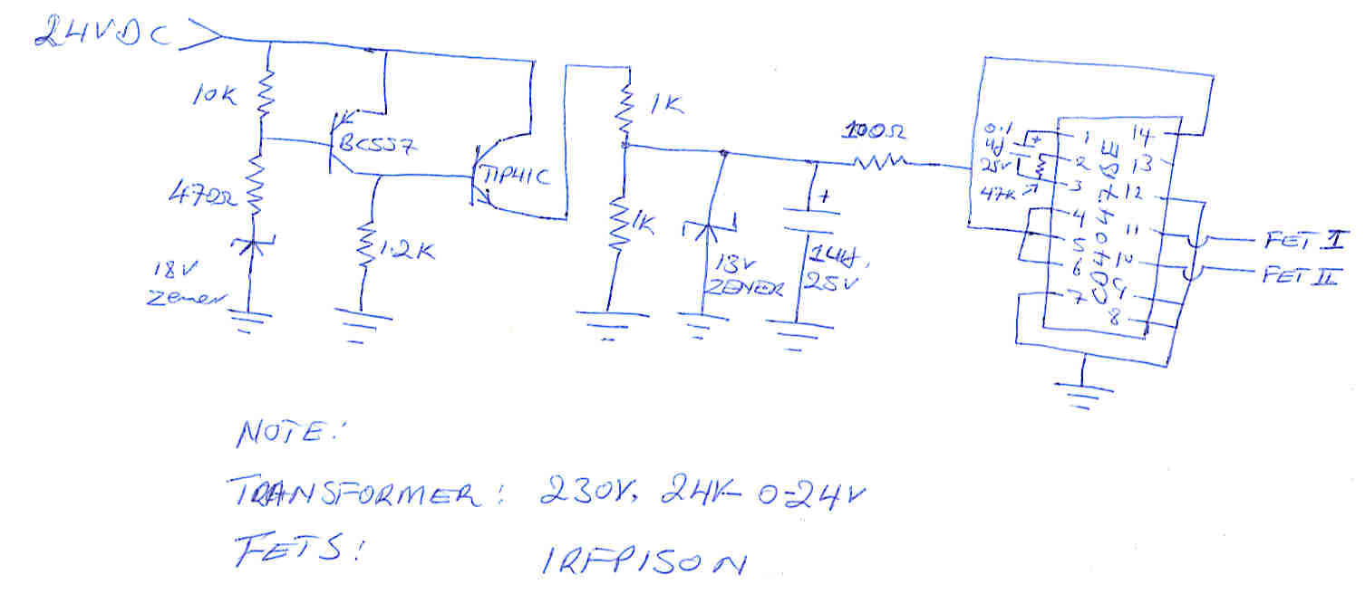 OSCil.jpg
55.59�KB
Reply author: audioguru
Replied on: Apr 24 2008 10:22:59 AM
Message:
The 0.1uF capacitor in the oscillator must not be an electrolytic type. Electrolytic capacitors are polarized for DC but in the CD4047 it has AC. An electrolytic capacitor has a horrible tolerance of -20% to +50%.
Use a metalized plastic film type of capacitor with a tight tolerance of 5%.
Why do you use a TIP41C power transistor in the circuit that has very low power. An ordinary little transistor will be fine.
Reply author: kivdenn
Replied on: Apr 24 2008 10:35:11 AM
Message:
Actualy I drew the diagram above some time back but now I use BC546 instead of the TIP41C. Talking about that, Is it posible to convert the low battery disconnect part of the circuit into a battery over voltage disconnect circuit.
Reply author: audioguru
Replied on: Apr 24 2008 12:18:48 PM
Message:
I think a window comparator using both comparators in an LM393 will be a good overvoltage cutoff and an undervoltage cutoff circuit.
Reply author: kivdenn
Replied on: Apr 25 2008 07:57:33 AM
Message:
I have always pleaded to you Audioguru to help me with that kind of circuit but all in vein so I think talking about it here is useless because at the end we shall never have it. Lets go with the cheap one that we have, rermnber a bird in hand is better than two in the bush.
Reply author: audioguru
Replied on: Apr 25 2008 09:03:31 AM
Message:
Please look at Window Comparator Circuit in Google. You will find some good circuits with explanations about how to set the threshold voltages.
Reply author: kivdenn
Replied on: Apr 25 2008 09:53:57 AM
Message:
I have to done all that but all in vein. All I find are fan speed control circuits and the rest but not low battery disconnect circuits
Reply author: audioguru
Replied on: Apr 25 2008 11:16:51 AM
Message:
I entered Window Comparator Circuit into Google. The very first link has this good circuit.
The output is low when the input voltage is higher than reference #2 and the output is also low when the input is less than reference #1.
The output is high (but with low current as determined by the LM393 dual comparator IC) when the input voltage is in the designed window.
Download Attachment: 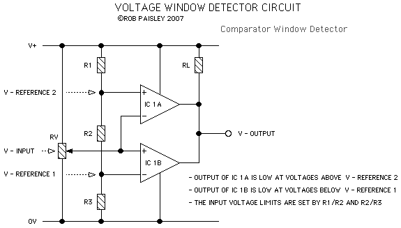 window comparator circuit.PNG
6.47 KB
Reply author: kivdenn
Replied on: Apr 26 2008 05:45:36 AM
Message:
quote:
Originally posted by audioguru
I entered Window Comparator Circuit into Google. The very first link has this good circuit.
The output is low when the input voltage is higher than reference #2 and the output is also low when the input is less than reference #1.
The output is high (but with low current as determined by the LM393 dual comparator IC) when the input voltage is in the designed window.
Download Attachment:window comparator circuit.PNG
6.47�KB
I have also seen the same circuit before but it is incoplete. The resistor values are not shown and also I dont believe it can drive a relay directly, it needs a current amplifier circuit which is not added it also doesnt indicate the exact voltages it was built for either 12v or 24V. Lets trey to solve those problems then it can serve its purpose. Otherwise thanks forall your effort.
Dennis
Reply author: audioguru
Replied on: Apr 26 2008 09:18:46 AM
Message:
quote:
Originally posted by kivdenn
I have also seen the same circuit before but it is incomplete. The resistor values are not shown
The datasheet for the comparator shows that its input current is extremely low so just about any resistor voltage dividers or zener diodes can be used.
quote:
I dont believe it can drive a relay directly, it needs a current amplifier circuit which is not added
Its datasheet shows that its minimum output current is only 4mA so a darlington transistor or Mosfet must be used to drive your big high current relay.
quote:
it also doesnt indicate the exact voltages it was built for either 12v or 24V
The voltage dividers or zener diodes are simple to calculate for any threshold voltages from 0V to 34.5V.
Reply author: audioguru
Replied on: Apr 27 2008 09:00:24 AM
Message:
Hi Juan,
All those old-fashioned transistors can be replaced by two modern Mosfets.
You have the power supply connected backwards on the CD4001. Pin 14 is supposed to be positive and pin 7 is supposed to be 0V.
The CD4047 and CD4001 both should be powered from a 100 ohm resistor in series from the 12V switch then a 16V zener diode to 0V at the ICs.
The ICs do not have enough output current to drive the transistors. Opamps were used in the original circuit because they have higher output current.
The transformer should be 9V-0V-9V for this modified sine-wave circuit so that the average output voltage is high enough.
The output needs to have a high voltage capacitor in series with a power resistor to reduce voltage spikes. They must match the transformer so use an oscilloscope to see what works best.
The power output from this circuit must be limited to 350W because the "modified sine-wave" creates peak currents in the transistors that are much higher than in a square-wave inverter circuit.
Reply author: audioguru
Replied on: Apr 28 2008 1:33:30 PM
Message:
I explained what needs to be fixed on your schematic.
I have very complicated circuits for Modified-Sine-Wave inverters that use Mosfets and other parts that are not available in the Philippines.
Reply author: audioguru
Replied on: Apr 28 2008 11:32:25 PM
Message:
quote:
Originally posted by JUAN DELA CRUZ
Meaning to say that both IC must have a regulated supply??? The 100 ohm is a BLEEDER Resistor that limit the current across the 16V Zener???
The ICs are very low current and operate from the 13.8V from the battery. The 16V zener diode limits voltage spikes.
quote:
Want OP_AMP did you used in the your circuit?? CD4001 is a OP-Amp right???
Didn't you see the 500W square-wave inverter that I helped fix with Rhonn from The Philippines?
Look in Google or in www.datasheetarchive.com at the CD4001 Cmos low current quad 2-input NOR logic gate. It is not an opamp.
quote:
You mean I need to use a BYPASS Capacitor across the Emitter Resistor??? What type & value must be the BYPASS Capacitor???
No. I did not say a bypass capacitor across the emitter resistor. I said, "The output needs to have a high voltage capacitor in series with a power resistor to reduce voltage spikes." They are in series and are directly across the output of the transformer. Every transformer needs different values. Use an oscilloscope to see which values work best.
Reply author: audioguru
Replied on: Apr 29 2008 12:19:31 AM
Message:
Ronnie made a square-wave inverter. It doesn't use the CD4001 logic gate. His inverter uses an LM358 dual opamp to boost the low current from the CD4047 Cmos IC.
You want to make an inverter that produces a modified sine-wave. The CD4001 Cmos makes the modified sine-wave. Its outputs also must have the current boosted with an LM358 dual opamp.
The modified sine-wave inverter has less output power and must use a 9V-0V-9V transformer.
I have never seen a transformer made in The Philippines. So I don't know the value of the resistor and capacitor voltage spike filter parts to match it. Maybe they are not needed.
Reply author: audioguru
Replied on: Apr 29 2008 11:16:35 AM
Message:
Use Ohm's Law to calculate the power dissipation in the 100 ohm resistor and in the zener diode.
The voltage spike might be 24V and occur for 1/100th the total time. So the 100 ohm resistor will have 24V - 16V= 8V across it for 100th the total time. Then its current is 8/100= 80mA for 100th of the time and it dissipates an average power of 0.006W. Use a 1/4W resistor. Or use 1/2W.
The power in the zener diode is about 4 times the power in the resistor so it dissipates an average power of only 0.024W. use a 400mW or 500mW zener diode.
The 4.7k resistors have the input current of the opamps in them. The datasheet for the opamps says that the max input current is only 0.24uA which is almost nothing. Use 1/4W resistors. Or use 1/2W.
You cannot calculate the resistor and capacitor across the output of the transformer unless you measure its leakage inductance and internal capacitance. Just connect an oscilloscope to the output and adjust the values for the best results. The voltage spikes are the highest without a load.
I think you should add a circuit that turns off the inverter when the battery voltage gets low so the low voltage doesn't destroy the battery or blow the fuse.
Reply author: audioguru
Replied on: Apr 29 2008 11:20:45 AM
Message:
Power the LM358 from the 12V feeding the 100 ohm resistor, not at the zener diode.
Reply author: audioguru
Replied on: Apr 30 2008 12:34:00 AM
Message:
Please look at the datasheets for the ICs.
1)The max allowed supply voltage for the CD4xxx is omly 18V. The max allowed supply voltage for the LM358 is 36V.
2) The operating current of a CD4xxx is almost nothing. The operating current of an LM358 when it drives 20mA into a transistor is 22mA which causes a voltage loss of 2.2V in the 100 ohms resistor.
Reply author: audioguru
Replied on: Apr 30 2008 10:23:52 AM
Message:
The "snubber" is a capacitor in series with a resistor and is connected at the output of the inverter to reduce voltage spikes. The capacitor must have a voltage rating that is higher than the peak output voltage.
Two back-to-back zener diodes in series with a resistor can also be used at the output to clamp voltage spikes.
We have talked about Low Voltage Cutoff circuits in this forum. It should have a flip-flop latch to make it stay turned off when the battery voltage rises when its load is disconnected.
Reply author: audioguru
Replied on: Apr 30 2008 11:44:19 PM
Message:
The Low Battery Cutoff thread was in September/07 and went on for many weeks.
You find it, I don't like doing things twice.
Here is my schematic:
Download Attachment: 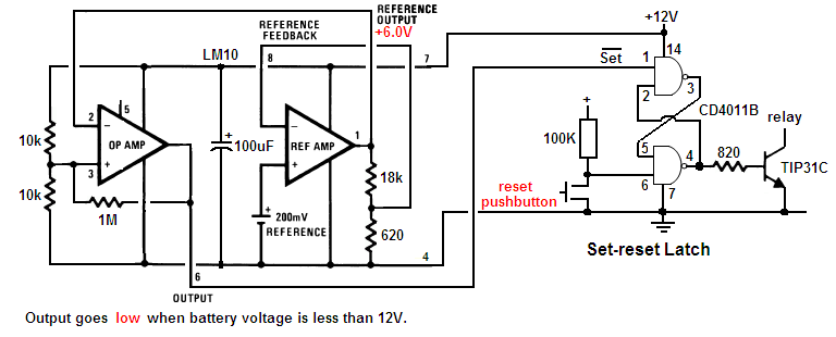 low battery detector.PNG
29.46 KB
Reply author: audioguru
Replied on: May 01 2008 09:14:07 AM
Message:
The LM10 has a low current opamp and a low current voltage reference inside. The other circuit uses much more current with a lousy old 741 opamp and a zener diode to do the voltage detection.
The first circuit has a flip-flop latch to keep the battery disconnected when its voltage rises when its load is disconnected.
The second circuit will detect a low battery and disconnect it or turn off the inverter's oscillator. Then it will detect the battery voltage rising without a load and connect it. It will turn on then turn off over and over.
The TIP31C is a power transistor that can activate then disconnect a high current relay that applies power to the inverter.
The second circuit has a small low current transistor that stops the CD4047 to stop the inverter.
The high current of the 741 opamp and zener diode in the second circuit needs re-design of the 100 ohm resistor and 16V zener diode to power them and protect them from voltage spikes.
The low current of the first circuit allows it to be powered from the 100 ohm resistor and 16V zener diode with the CD4047.
Two gates of the CD4001 are used for the modified sine-wave logic and the remaining two gates are used for the flip-flop latch.
Reply author: pebe
Replied on: May 02 2008 07:09:05 AM
Message:
Change the 330K resistor to 47K
Reply author: pebe
Replied on: May 02 2008 10:54:27 AM
Message:
The circuit should work as it is. Once the battery is cut off its voltage will have to rise to about 18V before the circuit will cut in again.
BTW. Your posts would be much easier to read if you did not write in COLORS.
Reply author: audioguru
Replied on: May 02 2008 1:32:09 PM
Message:
quote:
Originally posted by pebe
The circuit should work as it is. Once the battery is cut off its voltage will have to rise to about 18V before the circuit will cut in again.
Then the circuit will work only one time and never work again.
The circuit needs to have a reset pushbutton like my flip-flop circuit has.
The pushbutton in my circuit has a low current so a switch with gold contacts should be used. The gold plated contacts cost the same or pennies more than high current silver that corrodes and doesn't work with low currents.
I realize that one of my circuits uses a CD4001 quad NOR IC and the other circuit uses a CD4011 quad NAND IC. It wouldn't be difficult to change one to the other so a single logic IC can be used.
The LM10 in my circuit performs exactly the same function as the circuit with the lousy old 741 opamp. The LM10 doesn't have a 200mV battery. It has a 200mV adjustable voltage reference circuit plus an opamp inside.
The MJ11032 is a darlington that has a much higher voltage drop than a 2N3055 power transistor. The circuit should be re-designed for it.
Power Mosfets should be used instead.
You are talking about a lot of power. A 12V car battery will boil or explode when it tries to drive such a powerful load. Where will you get the huge custom-made transformer? Rediculous.
Download Attachment:
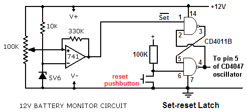 low battery cutoff again.PNG
10.26 KB
Reply author: senahia
Replied on: May 02 2008 1:35:53 PM
Message:
sir i will be very happy if you can send me schmatic diagram of 12vdc to 240vac inverter with solar and lead acide battery supplying the inverter for my project work please help me
Reply author: audioguru
Replied on: May 02 2008 3:22:54 PM
Message:
Hi Senahia,
We have many schematics for inverters in this foum. Some use old transistors and others use new efficient Mosfets. Some are 100W and others are almost 1000W.
Some have a square-wave outputs that don't power many electronic products. Some are modified sine-wave that is like most inverters in stores. Pure sine-wave inverters are too complicated for a forum.
You don't say what you want.
Solar power is a separate topic. Battery chargers are also a separate topic.
Reply author: audioguru
Replied on: May 03 2008 11:22:50 AM
Message:
Juan,
If you use a single CD4001 or CD4011 then the logic circuit must be re-designed for it.
Please look at the datasheet for the MJ11032.
With an output current of 25A its input current is only 250mA for it to have a max saturation voltage loss of 2.5V and it will dissipate a max average power of 31.3W. The 0.1 ohm emitter resistor will have a voltage loss of 2.5V and also dissipate an average power of 31.3W.
Four MJ11032 darlingtons on each side will have a max total input current of 1A and can be driven with a TIP31 or TIP41. They will add to the saturation voltage loss.
So nearly half the power from the battery is wasted.
Reply author: audioguru
Replied on: May 04 2008 12:07:37 AM
Message:
quote:
Originally posted by JUAN DELA CRUZ
If I will use only one MJ11032 (each side) to simulate the use of "8" 2N3055
And drive with TIP41.
Four 2N3055 transistors are good for about 50A. One MJ11032 darlington is good for about 50A. The TIP41 will have a max base current of about 50ma so another transistor is needed.
The total max saturation voltage loss will be about 5.7V which is too high. The max output power will be only about 340W if a lower voltage transformer is used. a lot of battery power is wasted if the transistors have low gain.
quote]The remaining components will be the same excluding the EMITTER Resistor?[/quote]
Yes, the emitter resistors are used to match the conduction of different transistors and are not needed with only a single transistor on each side.
Reply author: audioguru
Replied on: May 05 2008 11:50:28 AM
Message:
Welcome to 1978. Transistors are a poor choice for a high current switching circuit compared to modern Mosfets.
The BUT100 is the most powerful transistor I have ever seen. The two major electronics parts distributors in America have never seen it either. Maybe it is no longer made.
The transistors are not saturated switches, they are in a darlington configuration where their base-emitter voltages add to create a total voltage loss:
The max VBE for a BUT100 is 1.4V at 50A.
The max VBE for an NTE43 is about 1.2V at 2.5A.
The max VBE for a 2N2222 at 250mA is about 1.4V.
The total max voltage loss is 4.0V.
All transistors are different. You might be lucky and get some with high gain. Then the voltage loss is about 3.0V.
A "12V" battery is 12.8V to 13.8V when fully charged. So the pulses to the transformer will be 8.8V to 10.8V.
When the battery voltage drops to about 12.0V when it is nearly dead then the pulses to the transformer will be from 8.0V to 9.0V.
The transformer might be good and not have much loss, or it might be cheap and have a high loss.
In order for it to produce a modified sine-wave the low voltage winding must be rated for 0.707 times its ordinary voltage rating.
Use an 8V-0V-8V transformer.
The BUT100 transistors do not need an emitter resistor because there is only one transistor on each side.
The other two resistors and diode are needed on each side.
Reply author: audioguru
Replied on: May 06 2008 12:52:21 AM
Message:
You need to re-design the set-reset latch so it can use the unused gates of the CD4001. It is designed for a CD4011 now.
Reply author: audioguru
Replied on: May 06 2008 08:54:57 AM
Message:
The NTE180 is PNP not NPN so won't work in this circuit. The NTE181 is an NPN but its spec's stop at only 7.5A.
NTE transistors do not have full spec's because they are "replacements" for standard transistors that have full spec's.
The Japanese transistor will be fine as a pre-driver transistor.
The low battery cutoff circuit doesn't need the TIP31 and relay. Its output can stop the oscillator in the CD4047.
I don't think the set-reset latch should connect to pin 5 of the CD4047 because then one output will keep the transistors turned on and blow the fuse. I remember in January we discussed using a CD4025 three input NOR in the modified sine-wave circuit and the 3rd inputs are used to turn off all the transistors.
The transformer needs only one resistor in series with a capacitor at the output. The values depend on the transformer since every transformer is different. You attach an oscilloscope to the output and adjust the values so that the voltage spikes are reduced without a load.
Reply author: osama madni
Replied on: May 07 2008 09:44:53 AM
Message:
how i change transformer plz help me and capacitor
Reply author: osama madni
Replied on: May 07 2008 09:59:25 AM
Message:
sir i have a problem with transformer and capacitor in my envirement there is not found such capacitor
Reply author: audioguru
Replied on: May 07 2008 12:21:36 PM
Message:
Hi Osama,
Which circuit has a transformer you want to change? Why do you want to change it?
Which capacitor in what circuit are you talking about?
Reply author: audioguru
Replied on: May 08 2008 12:16:53 AM
Message:
The NTE line of ICs are replacements for real ICs. So their spec's are not detailed like real ICs. The datasheet lists spec's only at 7.5A. How much base current is needed at 20A and what is its max VBE??
I am not going to guess how well or how poorly it will perform.
i think there will be a high voltage loss.
The CD4025 is a NOR gate like a CD4001 except it has a 3rd input on each gate. When the 3rd input goes high from the low battery circuit then its Mosfet is turned off.
There are millions of opamps. Some have low current outputs and some have high current outputs. I have never looked for nor used one with high current outputs. Have fun looking for one.
Reply author: audioguru
Replied on: May 08 2008 09:03:57 AM
Message:
I was wrong when I talked about pin 5 of the CD4047. It will stop the oscillator then one side of transistors will be continuously conducting and then the fuse will blow. Use a CD4025 instead of a CD4001 to turn off both sides.
The peak current in the transistors of a modified sine-wave inverter is 1.414 times higher than the peak current in a square-wave inverter with the same power output. So if you want 500W output then the peak current in the transistors must be 50A x 1.414= 70.7A. A perfect job for Mosfets.
You don't have detailed spec's for the NTE181 transistors so you are just guessing about how much base current they need and how much voltage loss they will have.
Reply author: audioguru
Replied on: May 09 2008 10:37:35 AM
Message:
How would I know anything about which parts are available in The Philippines?
Here in Canada, any electronic part is available. There are thousands of Mosfets available to do the job.
I would not re-design the circuit so it can use many 2N3055 transistors.
Reply author: JUAN DELA CRUZ
Replied on: May 09 2008 11:31:19 PM
Message:
quote:
Originally posted by audioguru
How would I know anything about which parts are available in The Philippines?
Here in Canada, any electronic part is available. There are thousands of Mosfets available to do the job.quote:
THANK YOU MR.AUDIOGURU FOR YOUR REPLY....
......I think just name Commonly used MOSFET..or the one you've used maybe..Please just to have an IDEA
I would not re-design the circuit so it can use many 2N3055 transistors.
quote:
How is "4" 2N3055( in each side) used in the modified inverter capable of supplying "350W" output power even the Total output current in that "4" 2N3055 is just "20A"............
( 20A x 9V = 180W) because the output current from the 2N3055 driver is "2A" only that driving the four.For the reason that the output current from 2SC1061 is merely "200mA" (since the output current from the OP-AMP was "20mA").???
P.S.
What is the output Voltage & Current of CD4001(driving the dual OP-amp LM358)?????
Reply author: audioguru
Replied on: May 10 2008 05:57:31 AM
Message:
I have the datasheet for the IRFZ44 Mosfet on my hard drive. When it is turned on and is not too hot, its resistance is 0.028 ohms max. So with a current of 30A its voltage drop is only 0.84V and it heats with only 25.2W. There are better Mosfets.
The max output current of the opamp is 20mA. The max output current of the pre-driver transistor is 400mA. The max output current of the 2N3055 driver transistor is 8A. The max output current of the four 2N3055 transistors on each side is 60A if they have enough gain and if they don't get too hot.
A 2N3055 transistor has a max voltage drop of 3V when it has a collector current of 10A and a base current of 3.3A. Four of them in parallel will have a max voltage drop of 3V when the collector currents total 40A and the base currents total 13.2A.
The output is 350W so the input is about 420W. The peak current is 420W/9V= 46.7a which is 11.7A in each output transistor. So some 2N3055 transistors with low gain won't work in a 350W modified sine-wave inverter.
The CD4xxx series of ICs are Cmos. Their supply current is zero at low frequencies when they are not working hard charging and discharging stray capacitance.
Opamps have a very hin input resistance and a very low input current so the Cmos oscillator has nearly no load. The supply current of the LM358 opamp is low but has the input current of the first transistors.
It doesn't matter what the ouput voltage of the opamp is because it limits the current into the base of the first transistor. The total of the base-emitter voltages of half of the transistors limits the output voltage of the opamp.
Reply author: audioguru
Replied on: May 10 2008 11:42:58 AM
Message:
The max Vbe of the 2SD880 is about 1.0V, the two 2N3055 transistors is about 1.4V and the BUT100 is 2.0V. Then the voltage loss is 4.4V. Nearly half the power from the battery is wasted.
Reply author: audioguru
Replied on: May 11 2008 11:49:42 AM
Message:
Juan,
Do a couple of simple calculations:
1) Each 2N3055 transistor needs a max base current of 3.3A when its collector current is 10A. The max allowed current for the 2SD880 is too low.
2) The input current of whatever higher current transistor replacing the 2SD880 transistors is too high.
3) 100A through the 0.1 ohm resistors is a 10V loss!
4) Where are you going to find a 12V battery that can supply 200A without blowing up?
5) Your transformer is missing its center-tap. Where are you going to find such a huge transformer?
The voltage loss of the transistors depends on their gain. Each one has a different gain. So the output voltage will be too high with some transistors and too low with other transistors.
Reply author: audioguru
Replied on: May 12 2008 10:42:29 AM
Message:
Here we go again:
1) The max current from the opamps is only 20mA so the max input to each 2SD880 transistor is only 20mA and its max output current might be 300mA.
2) The max input to the 2N3055 transistor is 300mA and its max output might be 4.5A.
3) The max input to the BUT100 is 4.5A and its output might be 45A.
The peak output current is 49.8A so the RMS output current is 35.2A.
The peak output voltage is 8.2V so the RMS voltage is 5.8V. The transformer should be 6V-0V-6V for the output voltage to be correct.
The power into the transformer is 35.2A x 5.8V= 204W RMS. If the transistors have low gain then the output power and output voltage is less.
The transistors have a power loss which makes 95W of heat.
The average current from the battery is 24.9A.
If you use a pair of modern Mosfets then the power to the transformer will be about 400W and the voltage will be correct. 2 pairs of Mosfets make 800W.
The LM10 circuit has a low logic output when the battery voltage is low. It is designed to give a low logic input to a NAND gate. It must be re-designed to give a high logic input to a NOR gate. Or you can use the spare 3rd gate in the CD4025 to invert the output from the LM10.
The input current of CD4xxx Cmos gates is ZERO.
Reply author: audioguru
Replied on: May 13 2008 12:20:33 AM
Message:
quote:
Originally posted by JUAN DELA CRUZ
Can I use "2 Pair of IRFZ44 Mosfet" to obtain "800W" output..????
..........so if I'll use "3 pair of IRFZ44 Mosfet the output power will be "1200W"..?????
I think so but I have never tried to blow up a car battery with that much current.
How about this circuit( w/ LM741)???
It will do the same as the LM10 circuit.quote:
Can this circuit can supply "High" current to turn-off ......"TWO NOR GATE of CD4025"????
Its output voltage is low not high. It needs to use the 3rd unused gate in the CD4025 as an inverter to feed a logic high voltage to the CD4025 gates so they can turn off the Mosfets.quote:
Can I connect it directly to series resistor & Zener voltage spike filter???
I think so.
[quote]What is the purpose of "100K Pot."????.....What type???
...like the Pot. used in a Audio Amp.?????
.... How many Wattage is needed???
It adjusts the voltage for the low voltage cutoff to work. It is not a logarithmic volume control, it is a linear pot. Calculate the tiny amount of power it dissipates.
Reply author: audioguru
Replied on: May 13 2008 10:22:56 AM
Message:
A zener diode limits a voltage spike. A 15V regulator does not work when its input is less than 18V and a voltage spike goes through it because it reacts too slowly.
You found a very old circuit. I think the 1k resistors in series with the gates of the Mosfets should be 47 ohms. The resistors have an extremely low current in them so 1/4W is fine.
I think a transformer from a microwave oven is cheap. It is designed for full power for a short time so it wastes a lot of power if it is not at full power. It might overheat and its output voltage might have poor voltage regulation.
The transformer should be 8V-0-8V. With an 800W load the average current from the battery is about 75A. A huge car battery will last for about half an hour if it doesn't boil dry sooner.
Reply author: audioguru
Replied on: May 13 2008 10:03:11 PM
Message:
The capacitor in the snubber is certainly not 220uF. It is 220nF which is 1000 times smaller.
The values of the snubber and where they are placed depends on how the transformer makes voltage spikes. Each make of transformer is different.
Reply author: audioguru
Replied on: May 14 2008 3:03:53 PM
Message:
Most of your schematics have disappeared so I don't know what you are doing amymore.
Now you have inverted the input to the flip-plop latch so it won't work. You need to invert its output instead.
I always inhibit unused inputs by connecting them to the positive supplu or to ground like this:
Download Attachment: 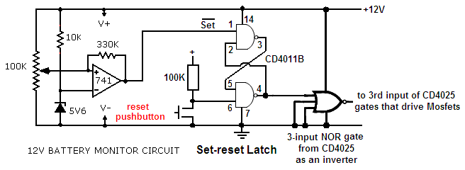 low battery cutoff again and again.PNG
14.48 KB
Reply author: audioguru
Replied on: May 15 2008 10:01:58 AM
Message:
I have never seen a transformer for a microwave oven that is made in your country.
The LM10 circuit works the same as the 741 circuit.
The reset pushbutton is normally open.
Reply author: senahia
Replied on: May 16 2008 08:54:41 AM
Message:
sir i will be happy if you can send me schmatic diagram of 12vdc to 240vac, and it will supplyed by solar panel of 12vdc and lead acid battery of 12vdc please i need immediate diagram for my projrct work(i need sine wave inverter diagram)
Reply author: audioguru
Replied on: May 16 2008 1:05:52 PM
Message:
quote:
Originally posted by JUAN DELA CRUZ
Regarding about the Xformer....If I'll make a 8v -0v- 8v primary winding(w/ 220V secondary) I'll turn the magnetic wire "8 times" in the iron core????
The turns ratio of the primary to the secondary determines the voltage. It probably will not be 8 times.
quote:
Do you have an short & overvoltage protection circuit that I can use w/ my Modified Sine Inverter to protect the Load...cause I'll using it to power a modified sine compatible COMPUTER.????
We talked about an over-voltage circuit in these forums recently. It was a window caomparator to turn off the Mosfets if the battery voltage is too high or too low.
You need to design a simple over-current detector circuit yourself.
quote:
What will be the value of ZENER diode to Protect the Power mosfet from "Voltage Spike" when the Battery clip is suddenly disconnected????[/b]
I don't know. Maybe a 16V/1W zener diode will work.
Reply author: audioguru
Replied on: May 17 2008 11:13:39 AM
Message:
You found a very old under-voltage and over-voltage circuit. A simpler modern circuit is made with two opamps or comparators performing as a window comparator. Dennis recently posted the schematic for his window comparator.
What will cause the 12V input voltage of your inverter to be too high?
Reply author: kivdenn
Replied on: May 17 2008 11:39:00 AM
Message:
Please can any one help me change this charger circuit http://www.aaroncake.net/circuits/charger2.asp to a 24V and also 48V charger circuit. Show me how to change the necessary parts especialy resistor values. Thanks
Dennis
Reply author: JUAN DELA CRUZ
Replied on: May 18 2008 12:25:48 AM
Message:
quote:
Originally posted by audioguru
You found a very old under-voltage and over-voltage circuit. A simpler modern circuit is made with two opamps or comparators performing as a window comparator. Dennis recently posted the schematic for his window comparator.
What will cause the 12V input voltage of your inverter to be too high?
Thank you again Mr. audioguru,
The 12V input voltage of my modified sine inverter is O.K.
........but my problem lies at the output of the Xformer(secondary side).The voltage in the output of my inverter varies.
(due to battery voltage variation, i.e. approx. 13.8V when full & 9V
when nearly discharge).
....do you think a Zener diode can regulate the output before coming to the primary side of the Xformer????
...the down side will be less power output because less RMS voltage will go to the primary winding right...???
.......but the output will be more stable.
OR....do think an "automatic voltage control" w/ SCR will be the answer????
quote:
P.S...........Do you think this charger(Aaron designed) can lenghten the charge of the battery of my Modified sine inverter if I'll power it in the output of my inverter & then automatically charge the battery (i.e. disconnect when fully charge & then charge it again when the charge is low)??????
Download Attachment:
 charger2-1.gif
4.32 KB
Thank you.....
Reply author: audioguru
Replied on: May 18 2008 10:56:57 AM
Message:
You should not regulate the output voltage of your simple inverter by using a huge zener diode to short its input with about 700W of wasted power. The inverter circuit is too simple for voltage regulation.
The inverter cannot charge itself because that is impossible perpetual motion. The input power to a charger is more than its output power so power is wasted and the battery will run down instead of charging.
The charger must be powered from the mains.
Reply author: JUAN DELA CRUZ
Replied on: May 19 2008 12:15:31 AM
Message:
quote:
Originally posted by audioguru
You should not regulate the output voltage of your simple inverter by using a huge zener diode to short its input with about 700W of wasted power. The inverter circuit is too simple for voltage regulation. [quote]
Thank you Mr. Audioguru....
What should I do so that the output voltage of my modified sine inverter will be more stable.
...you said that using a Zener to regulate the output will wasted a lot of power.
...what if the output of the individual power mosfet is regulated so that the voltage coming to the primary winding of the xformer is stable likewise the output will be stable right???
Thank you.
Reply author: audioguru
Replied on: May 19 2008 12:45:15 AM
Message:
If you adjust the input to the Mosfets so that they regulate the voltage to the transformer then the Mosfets will melt.
If the Mosfets must reduce the voltage by 2V then at 80A their power wasted is 160W in addition to their power loss.
Modern inverters use Pulse-Width-Modulation to have a regulated average current in the load. The Mosfets turn on completely and turn off completely to stay fairly cool.
Your simple inverter is not designed for Pulse-Width-Modulation. It is old and CHEAP!
Reply author: kivdenn
Replied on: May 19 2008 02:46:59 AM
Message:
quote:
Originally posted by JUAN DELA CRUZquote:
Originally posted by audioguru
You found a very old under-voltage and over-voltage circuit. A simpler modern circuit is made with two opamps or comparators performing as a window comparator. Dennis recently posted the schematic for his window comparator.
What will cause the 12V input voltage of your inverter to be too high?
Thank you again Mr. audioguru,
The 12V input voltage of my modified sine inverter is O.K.
........but my problem lies at the output of the Xformer(secondary side).The voltage in the output of my inverter varies.
(due to battery voltage variation, i.e. approx. 13.8V when full & 9V
when nearly discharge).
....do you think a Zener diode can regulate the output before coming to the primary side of the Xformer????
...the down side will be less power output because less RMS voltage will go to the primary winding right...???
.......but the output will be more stable.
OR....do think an "automatic voltage control" w/ SCR will be the answer????
quote:
P.S...........Do you think this charger(Aaron designed) can lenghten the charge of the battery of my Modified sine inverter if I'll power it in the output of my inverter & then automatically charge the battery (i.e. disconnect when fully charge & then charge it again when the charge is low)??????
Download Attachment:
4.32�KB
Thank you.....
Hey all,
I would like to modify this circuit to a 24V battery charger circuit. How do i do that I mean what parts should I change to what?.Thanks
Dennis
Reply author: audioguru
Replied on: May 19 2008 1:50:01 PM
Message:
I have never made a PWM circuit for an inverter. I made one to control the speed of a DC electric motor.
The LM393 and LM339 are not opamps. They are comparators. Their outputs are the collector of an NPN transistor not the complete output circuit that opamps have. The low battery cut-off circuit will need to be changed a little to use them.
Reply author: audioguru
Replied on: May 20 2008 12:00:48 PM
Message:
The comparator has only the collector of a single NPN transistor at its output. It needs a resistor connected to the positive supply to pull the output high. Opamps have multiple transistors and PNP pullup transistors at their outputs.
But the LM393 and LM339 comparators are low power so their minimum output current is low, only 6ma. Opamps have a minimum output current of 20mA.
Why use a low power dual comparator or quad comparator to replace a single more powerful opamp? What will you do with the extra comparators?
Reply author: audioguru
Replied on: May 21 2008 12:26:02 AM
Message:
Look at the datasheet for an LM1458 dual opamp. The MC1458 is the same. Their spec's are the same as a 741 opamp.
Why will the battery voltage be too high??
Reply author: audioguru
Replied on: May 21 2008 11:41:41 AM
Message:
The high and low cutoff circuit STOPS the inverter when the battery voltage is too high or is too low. I think Dennis uses it to stop the inverter from working when somebody connects a 24V battery to it.
The circuit with the two opamps as a window comparator does not regulate and does not sense the output voltage so it does not regulate the output voltage.
Reply author: rauf
Replied on: May 21 2008 12:44:09 PM
Message:
quote:
Originally posted by audioguruquote:
Originally posted by mrenjan
One Question to AudioGuru.. Is there any advantage of using 2N3055 instead of Mosfet's like IRF540 directly tied to CD 4047. We dont even need the OP-amps since Mosfet requires only less Drive current. Probably the only other change required is in the Transformer side (9-0-9 instead of 12-0-12). I thought the efficiancy of Mosfet is much higher than Transistor since leakage current is less. Not sure whether i am wrong.
2N3055 transistors were used in the 100W and 500W inverter because the circuit is very old and 2N3055 transistors atre available in countries that don't have Mosfets. Mosfets are much better.
The IRF540 Mosfet is also getting pretty old since much better Mosfets are available now.
The CD4047 can directly drive two Mosfets in an inverter and the output power depends on their current rating and the size of the heatsink. Cheap Chinese inverters use Mosfets.
Efficiency is determined by how much power is wasted as heat in the transistors when they conduct, not leakage current.
A 2N3055 transistor has a max saturation voltage of 3V at a collector current of 10A and a huge base current of 3.3A. That is 35W of heat for a 100W inverter.
An IRF540 Mosfet has a max saturation voltage of 0.44V at 10A so wastes only 4.4W in a 100W inverter. Better Mosfets would operate cooler and therefore the efficiency would be higher.
If you use a 9-0-9 transformer with Mosfets then with a fully charged battery at 13.8v the output voltage will be 170VAC instead of 115VAC or will be 341VAC instead of 230VAC.
If you use a 12-0-12 transformer with Mosfets and a fully charged battery then the output will be 128VAC instead of 115VAC and will be 256VAC instead of 230VAC.
Reply author: rauf
Replied on: May 21 2008 12:45:04 PM
Message:
quote:
Originally posted by audioguruquote:
Originally posted by mrenjan
One Question to AudioGuru.. Is there any advantage of using 2N3055 instead of Mosfet's like IRF540 directly tied to CD 4047. We dont even need the OP-amps since Mosfet requires only less Drive current. Probably the only other change required is in the Transformer side (9-0-9 instead of 12-0-12). I thought the efficiancy of Mosfet is much higher than Transistor since leakage current is less. Not sure whether i am wrong.
2N3055 transistors were used in the 100W and 500W inverter because the circuit is very old and 2N3055 transistors atre available in countries that don't have Mosfets. Mosfets are much better.
The IRF540 Mosfet is also getting pretty old since much better Mosfets are available now.
The CD4047 can directly drive two Mosfets in an inverter and the output power depends on their current rating and the size of the heatsink. Cheap Chinese inverters use Mosfets.
Efficiency is determined by how much power is wasted as heat in the transistors when they conduct, not leakage current.
A 2N3055 transistor has a max saturation voltage of 3V at a collector current of 10A and a huge base current of 3.3A. That is 35W of heat for a 100W inverter.
An IRF540 Mosfet has a max saturation voltage of 0.44V at 10A so wastes only 4.4W in a 100W inverter. Better Mosfets would operate cooler and therefore the efficiency would be higher.
If you use a 9-0-9 transformer with Mosfets then with a fully charged battery at 13.8v the output voltage will be 170VAC instead of 115VAC or will be 341VAC instead of 230VAC.
If you use a 12-0-12 transformer with Mosfets and a fully charged battery then the output will be 128VAC instead of 115VAC and will be 256VAC instead of 230VAC.
Reply author: audioguru
Replied on: May 22 2008 12:29:13 AM
Message:
A lead-acid battery is not fully charged when its voltage reaches a certain voltage. It is fully charged when its current drops to a certain low amount.
Go to the Battery University and read about it. http://www.batteryuniversity.com/partone-13.htm
Download Attachment: 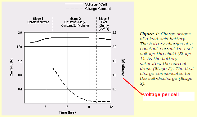 lead-acid battery charging.PNG
19.96 KB
Reply author: ElectroEgg
Replied on: May 22 2008 9:25:23 PM
Message:
Hi audioguru, as you can see I am new here. But not particularly new to electronics. I am a EEET level 1 student who likes to do practicals whenever I have free time. I am currently working on an inverter project. I've tried Aaron's schematic twice and ended up with 4 fried transistors and 3 fried capacitors. After that I decided to read the forums from pages 1-45 ![]() . Since you are the expert hear can you help me design an inverter circuit? All I have to start is a 10A Transformer with 12v-0-12v IN and 110/220v 60/50Hz OUT. This would be able to deliver 120W right? Please feel free to correct me if I am wrong, I am eager to learn. Oh! I would like to run a 110W Television or a 100W radio on it. Would these be able to work on a square wave?
. Since you are the expert hear can you help me design an inverter circuit? All I have to start is a 10A Transformer with 12v-0-12v IN and 110/220v 60/50Hz OUT. This would be able to deliver 120W right? Please feel free to correct me if I am wrong, I am eager to learn. Oh! I would like to run a 110W Television or a 100W radio on it. Would these be able to work on a square wave?
Reply author: audioguru
Replied on: May 23 2008 10:50:08 AM
Message:
Hi ElecroEgg,
I have already helped enough people make a very simple inverter on this website.
A radio and TV might not work from a square-wave inverter because their power supply usually runs on the peak voltage of a sine-wave which is 1.414 times higher than a square-wave. In The Philippines they have TVs that run from any voltage from 80V to 150V and they work fine from a simple square-wave inverter.
Your little transformer is designed to have an output of 12V-0V-12V when it has a load of 10A and the primary has 110V or 220V. Its output is probably 13.5V-0V-13.5V without a load. So when you turn it around and put a 12V square-wave into it, its output voltage will be 12V/13.5V= 0.89 times what you expect and lower when loaded.
A transformer with a higher power rating will not have such a high loss.
The circuit will not give a 12V square-wave because the transistors or Mosfets have a voltage loss (that heats them). So the output of an inverter using your transformer will be about 100W at 90V or 180V.
Reply author: ElectroEgg
Replied on: May 23 2008 9:53:02 PM
Message:
Hmmm...That's bad news Audioguru. Because that was the largest Transformer I got after checking various electronic shops. I payed a wopping $160TT ($20ca) for it and at that same store I saw a 400w inverter for $400. I will be at a great loss if I will have to buy another larger one (which obviously will cost more than the first). Oh well I got to forget my losses and see if I get a 15 or 20A Transformer. It's just that I get such a great feeling when I build something myself. Thanks a lot for your help.
Reply author: audioguru
Replied on: May 23 2008 11:01:42 PM
Message:
Hi ElectroEgg,
$20ca is nothing in Canada. I can buy a pretty good 100W inverter for $20ca. I think it has a modified sine-wave output but it mighr have a true sine-wave output so it can power anything up to 100W. It doesn't use a huge heavy transformer. It uses a voltage stepup circuit that operates at a high frequency so a small transformer is used and it uses high voltage Moafets instead of transistors.
Reply author: ElectroEgg
Replied on: May 24 2008 07:26:27 AM
Message:
Ok. Well I'm off for components searching. I hope I get the required ones for your 100w inverter. Since it's a square wave I will basically be able to operate only the lights at my home then. Hmmm....I'm just wondering. Do you know how to make a sine wave inveter also?
Reply author: kivdenn
Replied on: May 24 2008 09:54:51 AM
Message:
Hey am working on 48V DC-AC inverter circuit bellow.Please look at it and tell me if it can work.
Download Attachment: 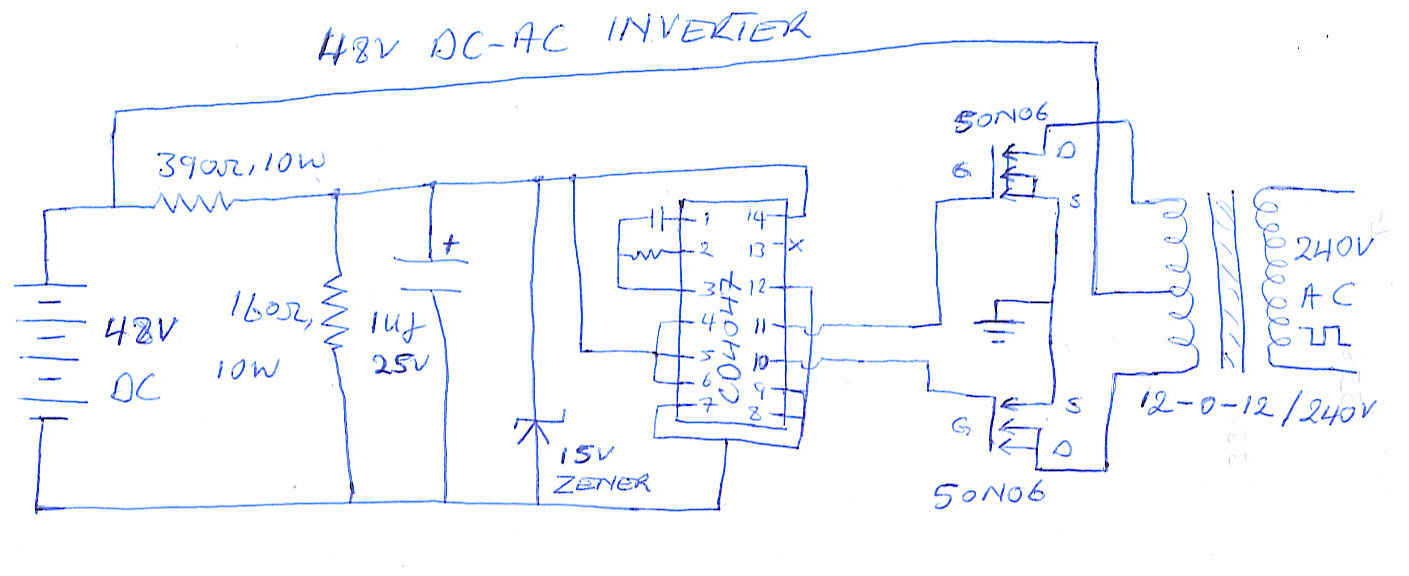 48v inverter.jpg
70.37 KB
I have also tried to make a 48V low battery disconnect circuit for it. please also have a look at it and tell me if it can work. Thanks
Dennis
Download Attachment: 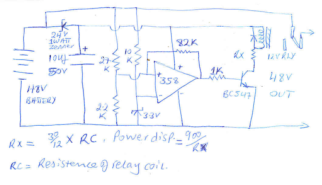 48v sensor.jpg
58.2 KB
Reply author: audioguru
Replied on: May 24 2008 6:59:18 PM
Message:
I am tired of checking your millions of circuits. Maybe somebody else can.
Reply author: ElectroEgg
Replied on: May 24 2008 9:43:48 PM
Message:
Hi Audioguru,
If you don't mind can you tell me what formulas you used and what calculations you did to determine that a 47k resistor will give 50Hz output and a 39K will give 60Hz output.
Reply author: kivdenn
Replied on: May 25 2008 02:56:06 AM
Message:
quote:
Originally posted by audioguru
I am tired of checking your millions of circuits. Maybe somebody else can.
Reply author: audioguru
Replied on: May 25 2008 12:48:26 PM
Message:
quote:
Originally posted by ElectroEgg
Hi Audioguru,
If you don't mind can you tell me what formulas you used and what calculations you did to determine that a 47k resistor will give 50Hz output and a 39K will give 60Hz output.
The formula is for The Classic Cmos Oscillator and is also shown on the datasheet for the CD4047 IC.
Download Attachment:
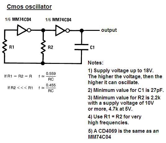 Cmos oscillator.PNG
24.34 KB
Reply author: ElectroEgg
Replied on: May 25 2008 6:10:21 PM
Message:
Oh I see. Thanks Audioguru
Reply author: kivdenn
Replied on: May 26 2008 02:40:37 AM
Message:
quote:
Originally posted by audioguru
I am tired of checking your millions of circuits. Maybe somebody else can.
Why, am I being so demanding or so bothering ?
Reply author: JUAN DELA CRUZ
Replied on: May 26 2008 04:09:51 AM
Message:
quote:
Originally posted by kivdennquote:
Originally posted by audioguru
I am tired of checking your millions of circuits. Maybe somebody else can.
Why, am I being so demanding or so bothering ?If so please tell me so that I un subscribe. Mr. Moderator I need your word on this because this is a very uncivilised way of talking to a person like me.
If you cant reply me and fed of my millions of circuits as you say just keep it to your self, no body needs to know your ill feelings.And that question was not specificaly directed at you Mr.Audioguru so I dont see why you atack me with such rague. Am so disapointed at MR. Villageguru.
Hi kivdenn....
Calm down my friend
Being a hobbyist like you in this forum, I know for a fact that Mr. Audioguru was a nice & cooperative person like Mr. Pebe.. They assist me in my modified sine inverter even though there is an obstacle between our language (not fluent in ENGLISH). In spite of everything they help me
So I think you should be nice also instead of being rude.
MR. AUDIOGURU ANSWERED OUR QUESTIONS AT NO COST....FOR FREE!!!
"ANSWERING NUMEROUS QUESTION POSTED IN THIS FORUM
..............IS NOT AN EASY TASK"
ESPECIALLY WHEN THERE IS A HINDRANCE BETWEEN LANGUAGES
DENNIS DON'T BE MAD. MR. AUDIOGURU IS TIRED NOT BY HELPING YOU OR ME.
HE IS A PERSON LIKE YOU. EVERYONE CAN FEEL WEARINESS.
NOBODY IS PERFECT.
Reply author: audioguru
Replied on: May 26 2008 09:26:12 AM
Message:
If you need an inverter (I don't need one) then buy an inexpensive Chinese one that is modified sine-wave and has modern parts inside using a small high frequency transformer. It even has a digital display showing how much power is being used and the remaining battery life.
Maybe somebody can take apart a modern Chinese inverter and post its schematic and parts list here.
Reply author: wasssup1990
Replied on: May 27 2008 07:59:18 AM
Message:
-
A PWM sine wave inverter can't be too expensive to make. I really think that. When I can, I'll make a parts list for a simple & straight forward PWM sine wave inverter. No more than 300W.
-
Reply author: audioguru
Replied on: May 27 2008 08:22:37 AM
Message:
The ferrite core for the high frequency transformer might be difficult to find or impossible to buy.
Maybe you must buy a cheap Chinese pure sine-wave inverter and use its transformer.
Reply author: JUAN DELA CRUZ
Replied on: May 27 2008 08:26:56 AM
Message:
Wasssup.........Johnny![]()
Do you have the schematic diagram of the sine wave inverter that you are talking about????
Reply author: wasssup1990
Replied on: May 27 2008 09:32:58 AM
Message:
quote:
From Audioguru:
The ferrite core for the high frequency transformer might be difficult to find or impossible to buy.
Yeah I think that might be the highest hurdle to jump over, but I have a few ideas. Keeping them to myself for now.
quote:
From Juan:
Do you have the schematic diagram of the sine wave inverter that you are talking about?
No, I haven't designed it yet. I better not get sidetracked too much, I have two projects underway. The sinewave inverter will be a switch from the kind of projects that I am currently doing and it'll be fun and very usefull.
Reply author: JUAN DELA CRUZ
Replied on: May 29 2008 04:13:14 AM
Message:
Wasssup...johnny![]()
Are you done with your sine wave inverter's schematic diagram?????
Reply author: wasssup1990
Replied on: May 29 2008 06:00:36 AM
Message:
No Juan. I said I have two projects underway and I shouldn't get sidetracked. It'll be a long time before I can put pen to paper for a sinewave inverter. See you! ![]()
Reply author: JUAN DELA CRUZ
Replied on: May 29 2008 06:58:27 AM
Message:
quote:
Originally posted by wasssup1990
No Juan. I said I have two projects underway and I shouldn't get sidetracked. It'll be a long time before I can put pen to paper for a sinewave inverter. See you!
Sorry for disturbing you Johnny
.........Do you know where can I find a schematic diagram of a TELEVISION aerial Signal Amplifier or VHF/ UHF amp. w/ a boost gain of Approx. 50dB?????
I've search in google and I found ckts w/ low gain(i.e. 10dB-20dB)
Thanks pal
Reply author: wasssup1990
Replied on: May 29 2008 10:00:29 AM
Message:
I could only find 20dB.
http://www.electronics-lab.com/projects/rf/003/index.html
http://www.newcircuits.com/project.php?id=prjsub003
http://www.elecfree.com/electronic/tv-signal-amplifier-by-bfr90-bfr91-bfw92/
Reply author: pebe
Replied on: May 29 2008 12:53:24 PM
Message:
quote:
Originally posted by JUAN DELA CRUZ
.........Do you know where can I find a schematic diagram of a TELEVISION aerial Signal Amplifier or VHF/ UHF amp. w/ a boost gain of Approx. 50dB?????
That's a voltage gain of around 300 times. You would have a job keeping such a beast tame in a single unit!
Where would you use such an amplifier?
Reply author: audioguru
Replied on: May 29 2008 6:45:11 PM
Message:
A TV that works properly is extremely sensitive. If it doesn't pick up a clear signal with a good antenna then the transmitter is too far away. An amplifier will just amplify its own noise.
Reply author: pebe
Replied on: May 30 2008 2:35:26 PM
Message:
quote:Its stated output of 90uV is in error - and means nothing. But it�s an ultra broadband amplifier that's wide open to interference and will give a poor signal/noise ratio over any narrow band of frequencies for which it will be used.
I've already searched those ckts. & as a matter of fact I'm already using this ckt.(below) for a long time. The downside of this ckt is that it has less selectivity(i.e.less channel/station). http://www.elecfree.com/electronic/tv-signal-amplifier-by-bfr90-bfr91-bfw92/
quote:Under those circumstances, TV reception would be the least of my worries.
I live in a country where typhoon visits regularly that knock-out power lines, cable system including TV aerial antenna. That's the reason why I need to boost the aerial signal for my TV.
quote:Absolutely correct.
I've ask this question already in another electronics forum website and they said building an aerial amp w/ such huge gain(50dB) will result for noise to be amplified also that won't benefit apprently right????
quote:A TV antenna is essentially a resonant half wave dipole matched to a 75ohm coaxial cable. It should feed into a matching 75 ohm load at the receiver or amplifier. I doubt the circuit you referred to will give a match anything like good enough.
I think I'll need to make a shorter aerial antenna*(PASSIVE) instead....but its gain will be lesser than the longer one. How about a home-made CABLE system????...Do you think its possible??????
Cable TV is an art in itself. It requires amplifier design and output distortion levels low enough to limit intermodulation and cross modulation to acceptable levels. It is not a practical task for a DIY enthusiast.
Reply author: ElectroEgg
Replied on: May 31 2008 12:55:06 AM
Message:
Helloooo. The topic here is about inverters. Is there anyone who can make adjustments to this square wave inverter circuit to produce a modified sinewave?
Download Attachment:  100w square-wave inverter.gif
15.86 KB
Reply author: pebe
Replied on: May 31 2008 01:20:57 AM
Message:
You might find help in this thread.
http://www.aaroncake.net/forum/topic.asp?TOPIC_ID=7123&whichpage=2
Reply author: ElectroEgg
Replied on: Jun 01 2008 6:44:40 PM
Message:
Hi Jaun. Thanks for the schematic. I would update you on my progress.
Reply author: Saso
Replied on: Jun 03 2008 3:48:41 PM
Message:
I have built 500W inverter with CD4047 and 2N3055 transistors. If I connect it to my desktop power supply it works relatively OK but if I connect it to car battery it does not work � there is no output, CD4047 dies and transistors and 10W resistors heat up.
When it is connected to desktop supply and it works the measurements are (for instance):
- Power supply 13V, 4A
- AC output 110 V
- DC output (after diode bridge and capacitors) 95V, 0,48A
It works fine with heavier load also. Highest reading was almost 10A input and 1A output. That is as high I can go with this power supply.
My transformer is 13,8-0-13,8/110V.
I have tried everything I could think of according to my limited knowledge of electronics.
Would you be so kind and help me to solve this problem - why it does not work with the battery.
Saso
Reply author: audioguru
Replied on: Jun 03 2008 7:15:59 PM
Message:
Hi Saso,
You forgot to post the schematic of your 500W inverter.
Its CD4047 needs to be fed through a 100 ohm resistor then a 15V zener diode to ground to protect it from spikes.
Your power supply has an output of only 13V x 4A= 52W. A 500w inverter needs an input of 600W. A huge difference.
The voltage rating of your transformer is wrong. The RMS voltage at the output of yje inverter is probably a lot lower than an ordinary meter measures its square-wave.
Post the schematic and we will fix it for you.
Reply author: Saso
Replied on: Jun 03 2008 7:36:39 PM
Message:
Thank you Audioguru. I have used the schematic that you have modified http://www.aaroncake.net/forum/uploaded/Audioguru/2007212205318_500Watts_Inverter-small.PNG
I'll add 100 ohm resistor and the zener.
Reply author: audioguru
Replied on: Jun 03 2008 10:31:58 PM
Message:
The 500W inverter circuit is simple and produces a square-wave. Many electronic products won't operate properly from a square-wave inverter.
The CD4047 IC also needs a bypass capacitor like this:
Download Attachment: 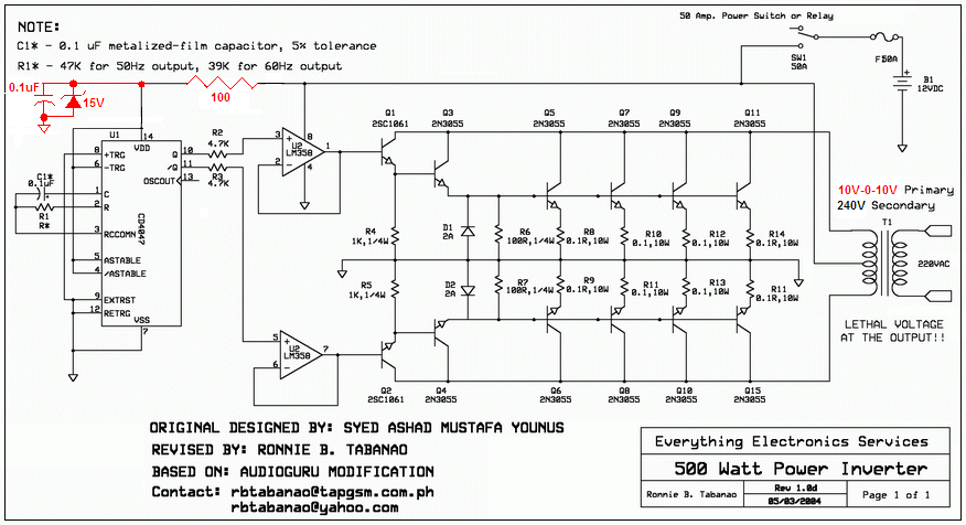 500W inverter smalll pic.PNG
160.81 KB
Reply author: Saso
Replied on: Jun 04 2008 04:02:28 AM
Message:
Audioguru, thanks. It works.
I have one more question. If there is no load at output the voltage is 150V. If I connect the load, the voltage drops. If the load draws 0,07A the voltage is 100V and if the load draws 1A the voltage drops to 75V. Is that normal? Can I prevent that?
Saso
Reply author: audioguru
Replied on: Jun 04 2008 12:01:56 PM
Message:
The output is a square-wave that must be measured with an oscilloscope or a "True-RMS" meter.
The battery must be a huge lead-acid one from a big car or a "deep discharge" one from a motor home.
Then when the battery is fully charged at 13.2V the square-wave output will be about 130VAC RMS without a load and about 106VAC RMS with a 500W load. The transformer should be 10V-0V-10V to 120V.
Reply author: kivdenn
Replied on: Jun 09 2008 03:37:03 AM
Message:
Hey Juan why did you opt for this and left the one that used the CD4047 and CD4025 ICs that produced a modified sine wave output?
Thanks
Reply author: pebe
Replied on: Jun 09 2008 08:15:34 AM
Message:
Juan,
There is a mistake on your wiring diagram!
The cathodes of D3 and D4 should go to CE (pin13) NOT to ground. Wiring the way you have them will cause them, or the 4017, to pop! Your earlier circuit showed them wired correctly.
Reply author: JUAN DELA CRUZ
Replied on: Jun 10 2008 04:14:14 AM
Message:
To Kivdenn:
> This modified-sine inverter is
better than MSW inverter w/ CD4047 and CD4025 ICs. For the reason that this MSW inverter has a 'stable voltage output'.
To Mr. Pebe:
> Ooops! Sorry about that. I'll fix it.
HERE IS THE EDITED DIAGRAM:
D3 & D4 IS CONNECTED TO PIN 13 & R9 & C7
(CIRCUIT WHERE REMOVED DUE TO TECHNICAL REASON)
Reply author: audioguru
Replied on: Jun 10 2008 11:39:28 AM
Message:
Now the schematic is confusing.
D3 and D4 connect to pin 5-and-a-half on the CD4017.
EDIT:
Thanks again Juan for fixing the schematic.
Reply author: kivdenn
Replied on: Jun 11 2008 10:23:19 AM
Message:
So what do you mean? is the circuit OK or NOT? Thanks
Dennis
Reply author: audioguru
Replied on: Jun 11 2008 12:03:54 PM
Message:
quote:
Originally posted by kivdenn
So what do you mean? is the circuit OK or NOT? Thanks
Dennis
Juan corrected the errors on his schematic so it should be fine.
Reply author: kivdenn
Replied on: Jun 14 2008 03:04:13 AM
Message:
How can I modify this for 24V and 48V battery outputs
Reply author: audioguru
Replied on: Jun 14 2008 3:36:41 PM
Message:
Juan's circuit can be completely re-designed to work from 24V or 48V.
Reply author: JUAN DELA CRUZ
Replied on: Jun 15 2008 01:46:47 AM
Message:
quote:
Originally posted by kivdenn
How can I modify this for 24V and 48V battery outputs
Hi Dennis...
Why will you need to modify the MS-wave inverter for 24V/48V???
.......to increase the output of the MS-wave inverter???
I think you just 'arrange your battery bank in parallel' (add a Power mosfets or just use better mosfet likewise change your Xformer to handle huge current) to increase the output of the MS-wave inverter.
Hope it helps you....
Reply author: kivdenn
Replied on: Jun 16 2008 07:02:37 AM
Message:
quote:
Originally posted by audioguru
Juan's circuit can be completely re-designed to work from 24V or 48V.
Please help me and show me how to do it because I have always tried to do it but the fets blow on each power on. thanks
Reply author: steven
Replied on: Jun 17 2008 11:46:22 AM
Message:
hi,i have a question wanna to ask upstairs,what's the friquency(it seems only 0.5Hz)?what do you wanna to use for? your input fuse is 5A,but your switching transistor is 3055*2? How many Watt do u wanna to output? i am engineer for power supply, i think i can help u to complet this case.
Reply author: pebe
Replied on: Jun 17 2008 12:47:50 PM
Message:
quote:Which circuit are you asking about?
Originally posted by steven
hi,i have a question wanna to ask upstairs,what's the friquency(it seems only 0.5Hz)?what do you wanna to use for? your input fuse is 5A,but your switching transistor is 3055*2? How many Watt do u wanna to output? i am engineer for power supply, i think i can help u to complet this case.
Reply author: kivdenn
Replied on: Jun 18 2008 04:45:00 AM
Message:
I think he means my 24V/48V inverter circuit. The frequency is 50Hz and the output is determined by the transformer size.Dennis
Reply author: kivdenn
Replied on: Jun 19 2008 04:05:22 AM
Message:
Hullo Juan this modified sine wave inverter has failed to run my fridge yet the fridge is rated 83Watts and the inverter is producing over 1000VA because it it using a 30Amp transformer and 8 mosfets of 50amps each paraleled on each chanel of the oscilator. Why?
Dennis
Reply author: JUAN DELA CRUZ
Replied on: Jun 21 2008 03:50:28 AM
Message:
[quote]Originally posted by kivdenn
Hullo Juan this modified sine wave inverter has failed to run my fridge yet the fridge is rated 83Watts
Hi Dennis...![]()
What M.S-wave inverter are you refering with????.....
........my M.S.-wave Inverter???
and the inverter is producing over 1000VA because it it using a 30Amp transformer and 8 mosfets of 50amps each paraleled on each chanel of the oscilator. Why?
My M.S-wave INVERTER was rated '500W OUTPUT' only not 1000W. It uses '1000W' transformer from old microwave oven. I remove the secondary winding (rated 2000V) & rewound it for my primary winding w/ centapped (rated 12V-0V-12V/ 105Amperes using #3 AWG magnetic wire).
I used 'two pairs' of IRFZ44 Mosfet to obtain 500W output.
You can increase its output power by using better Power mosfets, but,
........ be sure to use batteries (paralled) & transformer(high rated power in WATTs) that can handle your desires 'Huge output'.
..Your Fridge has a motor that needs 'high current' to start.
That's why it didn't run it 'coz its output is limited for only 500W.
Reply author: j12
Replied on: Jul 02 2008 1:37:37 PM
Message:
can any 1 tell me if we r not conecting the t1 step up transformer what was the reading of the reading of circuit and what was rga right conection of 2n3055 i am confuced to conecting, or what was the right way to use the microwave transformer in this circuit
plzz help me ![]()
Reply author: j12
Replied on: Jul 02 2008 1:38:59 PM
Message:
can any 1 tell me if we r not conecting the t1 step up transformer what was the reading of the reading of circuit and what was rga right conection of 2n3055 i am confuced to conecting, or what was the right way to use the microwave transformer in this circuit
plzz help me ![]()
Reply author: audioguru
Replied on: Jul 02 2008 6:23:10 PM
Message:
Hi John J12,
Which inverter circuit are you making?
The original project on this site with only two 2N3055 transistors does not work. A rewound microwave oven transformer won't make it work better.
Reply author: j12
Replied on: Jul 03 2008 06:46:37 AM
Message:
hi 2
i am talking about
12V to 120V Inverter
Reply author: audioguru
Replied on: Jul 04 2008 7:31:41 PM
Message:
Hi John J12,
The 12V to 120V Inverter project has many things wrong with it so it does not work.
Reply author: j12
Replied on: Jul 06 2008 3:45:43 PM
Message:
ohh man !!!![]()
did u have any dc to ac converter diagram , i want to convert 12vdc to ac current ,i have a step up trams former i give her 12vac they convert 215vac, so i want a dc to ac converter diagram.
Reply author: audioguru
Replied on: Jul 06 2008 6:07:21 PM
Message:
A simple square-wave inverter will not power many electronic products properly and speed controllers for power tools will not work.
How much power do you need?
Do you have a huge battery to power it?
Reply author: j12
Replied on: Jul 07 2008 3:24:06 PM
Message:
thankx for replying ![]()
"audioguru"
i wanat to run only 1 tv and 1 music system
now i have only a 12v 60A car battery
Reply author: audioguru
Replied on: Jul 08 2008 01:45:33 AM
Message:
Your TV and music system is made to run from a sine-wave and probably will not work properly from the square-wave of a simple inverter. They will probably work from a modified sine-wave inverter circuit.
There are some good modified sine-wave and pure sine-wave inverters sold at a low price. They are made in China and cost much less than you can make one.
Your battery is only 720Wh. It will run a medium TV and medium music system for about 3.5 hours.
Reply author: j12
Replied on: Jul 08 2008 03:23:37 AM
Message:
thankx dear
Reply author: almaleky
Replied on: Sep 12 2008 11:52:19 AM
Message:
HELLO YS..
I WANT TO UNDERSTAND HOW TH BOTH BIAS IS CONNECTED TO BOTH COLLECTOR>
PLEASE EXPLAIN THIS CIRCUIT IN POINTS...VERY THANKS
Reply author: audioguru
Replied on: Sep 12 2008 1:33:54 PM
Message:
The circuit is a transistor multivibrator. Look in Google but there are a few circuits shown with backwards capacitors (like this one).
Please keep Muhammed out of here.
Please turn off the CAPITALS.
Reply author: almaleky
Replied on: Sep 12 2008 4:01:41 PM
Message:
ok,i willnot write capital..
sorry,prophet muhammad is my leader and prophet .he is in my heart.this is freedom!!!
very thanks the circuit start to be unterstanded
Reply author: audioguru
Replied on: Sep 12 2008 8:27:40 PM
Message:
Please keep Muhammad away from here.
We talk about electronic circuits, not about your religion.
Reply author: julep
Replied on: Sep 21 2008 11:02:34 PM
Message:
Hi,moderator,hi audioguru, im julep from Philippines, i want to ask for your help, i have read a lot in this forum about inverter, and it seems that you have i broad knowledge about this, i would like to ask if there is a working circuit of inverter here,12vdc-230ac atleast 500watts, it doesn't matter to me what output waveform it produce. i planned it also to have it a low battery cut-off device. i have search the entire net, and i'm afraid to gamble in making it,it will waste my budget. Please help me to have a working circuit. thankyou in advance.. and Godspeed...
Reply author: julep
Replied on: Sep 21 2008 11:05:08 PM
Message:
Hi moderator, hi audioguru.. you can email me at julep_roxas@yahoo.com regarding with my above request. i really need your help.. wish u all luck and good health.. thankyou in advance and morepower to your site.. Godspeed...
Reply author: dragan
Replied on: Sep 30 2008 08:30:48 AM
Message:
i need convertors 12v=/220v~
Reply author: gim
Replied on: Oct 01 2008 06:55:56 AM
Message:
Hi. I am by no means an expert on these things but...
I love the simplicity of this circuit, also its symmetry. It has some imperfections though. As someone else said, the thing is a multivibrator. That is, two oscillators that are interdependent.
One of the problems with this circuit is that there is no way to control the frequency. The impedance of a capacitor decreases as the frequency increases. If the thing oscillates at high frequencies, very high currents will flow through the capacitors. That probably explains the propensity of the capacitors to explode.
It probably also explains why some people have reported low voltages on the output. Iron cored transformers are not designed to work at high frequencies.
I think that someone, with more knowledge than myself, could make a fairly simple modification to this circuit, to make it run at about 60 Hz. That should (I think) solve the other problems.
Reply author: pebe
Replied on: Oct 01 2008 07:21:32 AM
Message:
quote:Don't bother. The circuit is CRAP!
Originally posted by gim
I think that someone, with more knowledge than myself, could make a fairly simple modification to this circuit, to make it run at about 60 Hz. That should (I think) solve the other problems.
It should have been removed from the board a long time ago!
Reply author: audioguru
Replied on: Oct 01 2008 11:24:25 AM
Message:
There is only one oscillator, not two. Tt is a multivibrator. Look at it in Google. It probably operates at exactly 60Hz.
The polarity of the capacitors is backwards.
The transistors have avalanche breakdown of their emitter-base junctions (max allowed voltage is 7V) because the capacitors are charged to about 23V then they try to drive the base of the transistor to negative 22V. Therefore the capacitors have a very high discharge current which overheats them even if their polarity is correct.
The transistors do not have enough base current for a powerful inverter so the output power is very low.
Reply author: gim
Replied on: Oct 02 2008 10:24:25 AM
Message:
Thanks for the detailed analysis.
According to Wikipedia, for a multivibrator, "The period will also depend on any current drawn from the output..."
So maybe it won't run at exactly 60 Hz?
The circuit of this inverter is slightly different from the basic multivibrator, because the +V feed to the collectors of the transistors passes through the load, which is variable.
Reply author: gim
Replied on: Oct 09 2008 09:01:45 AM
Message:
quote: Now the schematic is confusing.
D3 and D4 connect to pin 5-and-a-half on the CD4017.
EDIT:
Thanks again Juan for fixing the schematic.
Can someone please direct me to the schematic referred to here? I can't find it. Thanks.
Reply author: gim
Replied on: Oct 09 2008 09:12:34 AM
Message:
I have built a modified square wave inverter according to the schematic I found at http://www.discovercircuits.com/C/co-dctoac.htm (Third circuit in the list).
This inverter works fine, at low power. I have not tried it at high power yet. It does not require a centre tapped transformer. I have used 12amp MTP3055E MOSFETs rather than the 0.5amp BS170s.
Audioguru, if I may ask you a question. In a previous post you stated that the gates of MOSFETs should be fed through a (47 ohm) resistor, to prevent high frequency oscillation. The schematic I have used does not have any such resistors. How necessary are they?
Reply author: audioguru
Replied on: Oct 09 2008 10:45:34 AM
Message:
quote:
Originally posted by gim
I have built a modified square wave inverter according to the schematic I found at http://www.discovercircuits.com/C/co-dctoac.htm (Third circuit in the list).
This inverter works fine, at low power. I have not tried it at high power yet. It does not require a centre tapped transformer. I have used 12amp MTP3055E MOSFETs rather than the 0.5amp BS170s.
Audioguru, if I may ask you a question. In a previous post you stated that the gates of MOSFETs should be fed through a (47 ohm) resistor, to prevent high frequency oscillation. The schematic I have used does not have any such resistors. How necessary are they?
The BS170 is a tiny low power Mosfet. Its input capacitance is only 60pF max so it probably doesn't oscillate without a resistor in series with its gate.
Real power Mosfets have an input capacitance almost 200 times higher so they oscillate at a high frequency if the gate doesn't have a series resistor mounted closeby.
Reply author: 4396459saad
Replied on: Oct 11 2008 11:22:02 AM
Message:
hi i am making a ups for my project
i need a ckt diag of a ups that could drive a load of 100w for 10min
Reply author: yunusu
Replied on: Oct 12 2008 11:17:39 AM
Message:
It's possible to adjast the output fo an inverter
by using a simple variable resustor in it's
oscilator ? how
Reply author: audioguru
Replied on: Oct 12 2008 3:08:18 PM
Message:
quote:
Originally posted by yunusu
It's possible to adjast the output fo an inverter
by using a simple variable resustor in it's
oscilator ? how
Adjust what? A variable resistor can adjust the frequency.
Reply author: forlan12
Replied on: Oct 13 2008 03:45:41 AM
Message:
can u guys help me.
in my project, i have to replace the inverter IC into PIC microcontroller.
1)i want to find the replacement component for 2sj471- pnp mosfet.
2)what specification should i look in the datasheet?
3)is it irf9450 suitable for replace 2sj471? 
Reply author: audioguru
Replied on: Oct 13 2008 12:06:51 PM
Message:
You found a low power Japanese inverter circuit. Of course it uses Japanese parts.
Its output is a simple square-wave that will not drive many electronic products properly.
It uses 4 Mosfets because it doesn't use a center-tapped transformer when it needs only 2 N-channel Mosfets.
Its performance is horrible because it does not have voltage regulation. With no load then its output voltage is 10% high. With a 40W load then the output voltage is correct. With a 140W load then the output voltage is 10% low.
If you use a center-tapped transformer then the output power would be double with only 2 of those Mosfets.
http://hobby_elec.piclist.com/e_ckt30.htm
what will a PIC do? If it produces a high frequency PWM signal to make a stepped sine-wave then the transformer must be different and the transistors must switch quicker.
Download Attachment: 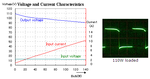 110W inverter.PNG
50.02 KB
Reply author: forlan12
Replied on: Oct 13 2008 2:44:23 PM
Message:
quote:
If you use a center-tapped transformer then the output power would be double with only 2 of those Mosfets.
what will a PIC do? If it produces a high frequency PWM signal to make a stepped sine-wave then the transformer must be different and the transistors must switch quicker.
PIC produce PWM signal. i plan to make sine-wave inverter 12/240V.
plz corect me if i wrong.
the transformer should be 12V-0V-12V and its center-tap connects to the positive supply. The sources of the N-channel Mosfets (2sk2956)connect to ground.
btw what mosfet should i use? is it IRF9540 suitable for replacement 2sj471?
Download Attachment:
 power invert edit.GIF
9.5 KB
Reply author: audioguru
Replied on: Oct 13 2008 6:40:28 PM
Message:
The IRF9540 is a weak low power P-channel Mosfet. It is not needed with the center-tapped transformer.
Your new circuit shows a low frequency square-wave inverter, not a high frequency PWM sine-wave one.
The peak voltage of a square-wave is the same as its RMS voltage. But the peak voltage of a sine-wave is 1.414 times higher so the transformer must be about 9V-0V-9V to make the higher peak voltage for a sine-wave. The PWM transformer must be a small high frequency ferrite one.
Reply author: forlan12
Replied on: Oct 14 2008 12:30:15 AM
Message:
is it ok, if i change the circuit by changing the placement of mosfet into full-bridge.
all the mosfet are 2sk2956 npn.
any recommend , what mosfet should i use other than 2sk2965?
i prefer mosfet IRF brand 
Download Attachment:  power invert2.GIF
10.35 KB
Reply author: audioguru
Replied on: Oct 14 2008 10:58:30 AM
Message:
quote:
Originally posted by forlan12
is it ok, if i change the circuit by changing the placement of mosfet into full-bridge.
It won't work because the upper N-channel Mosfets need a gate voltage that is 10V higher than the source voltage. Then the gate voltage must be +22V to +24V.
Usually a full-bridge Mosfet driver IC is used that has a voltage doubler circuit inside for driving the upper (high side) Mosfets.
The Mosfets are selected for the amount of output power you want from the inverter.
Reply author: mleiss
Replied on: Oct 18 2008 01:02:18 AM
Message:
This is in regards to simply multivibrators like the original schematics shown. With switchers and inverters it is wise to know if there is a "dead band" between the switching pulses, especially if there is more than one transistor in the switching circuit. When one transistor switches off, the other one is turning on and there is a moment in time where both are on, though very brief. This has a detrimental effect on your efficiency of the circuit. Also, since both transistors are on for that brief moment, guess what this does to the current... All of the current in the circuit goes to ground, essentially removing the stored energy that is in the system and effecting efficiency because now your supply has to provide additional energy to make up for the losses. So to make this work, and I haven't tried this circuit out myself either, I believe that a more sophisticated clocking source would be required to allow about 200ns to 400ns of a dead zone between each triggering pulse of the transistors.
Reply author: gim
Replied on: Nov 07 2008 04:27:12 AM
Message:
Audioguru, if I may ask you a question.
I have built an inverter, which works, as I have mentioned before. I have added to it a light sensitive switch, so that it turns on in daylight, and turns off in darkness. The switch consists of an LDR connected to a 555 timer IC, which does the switching, and in turn drives a MTP3055E MOSFET through a 47 ohm resistor.
The trouble is, sometimes, the circuit (I guess that is the MOSFET) oscillates at radio frequencies. It makes quite loud intereference on the audio of my TV.
Can you suggest a way to stop this HF oscillation? Would increasing the gate resistor of the MOSFET do it, and if so, what value should I use?
Reply author: audioguru
Replied on: Nov 07 2008 12:25:30 PM
Message:
A resistor in series with the gate of a Mosfet stops it from oscillating at VHF frequencies. It should be mounted directly at the gate pin, not connected by a wire. 4.7 ohms to 100 ohms should work fine.
Reply author: mleiss
Replied on: Nov 11 2008 9:57:17 PM
Message:
If this doesn't work for you, try a RC snubber network between the drain to source of your MOSFET. You may have incurred a resonance or ringing between the leakage inductance of the transformer and the output capacitance of the MOSFET. Adding the RC snubber will help to reduce the ringing.
First, figure out what the frequency of the oscillation is, if you have a way. You can use this frequency to calculate the leakage inductance of your transformer with the following equation: L = 1/((2*pi*frequency)^2*Capacitance).
Select a capacitor that is about 3 to 4 times larger than the output capacitance of your chosen MOSFET. This should reduce the frequency of the resonance by a factor of 2. Then calculate your resistance based on the equation for characteristic impedance of a parallel resonant circuit as in the following equation: R = sqrt(L/C).
After the R-C circuit has been calculated, again place the resistor and capacitor in series between the drain and source of your MOSFET. Ensure you have a very good ground and minimize the lead length between the capacitor and ground. If the connections between all of these elements are not short, parasitic elements of a long wire can change this circuit and you will not dampen out the oscillations as you thought you would.
Hope this helps and good luck!
Reply author: fallo
Replied on: Nov 19 2008 12:52:37 PM
Message:
Hi, I�m currently working in building a photovoltaic system to power a complete room and at the end a complete house, do you have any idea of how much power would it need to generate. I�m asking this cause obviously I need an inverter DC-AC, and I want to try building it my own, or would it be better if I buy it custom made? I appreciate your suggestions, thanks.
Fallo
Reply author: audioguru
Replied on: Nov 19 2008 2:25:53 PM
Message:
Simply add the amount of power you need for everything in the room. Then figure that not everything will be turned on at the same time. The result is the amount of power the inverter must supply.
Good inverters work well and are inexpensive. Solar panels are expensive. Windmills are less expensive.
Reply author: paul_ma7
Replied on: Nov 22 2008 11:17:32 PM
Message:
i build the inverter but for some reason the current
is very low it will only handle about 2 amperes,
i'm thinking it might have something with the battery?
my batt is 12.7v and 7 amp, do i need to use a car battery?
also i'm not using the hep diodes, i'm using a regular silicon diode,
Reply author: paul_ma7
Replied on: Nov 22 2008 11:29:30 PM
Message:
also i forgot to mention that i'm using a 150w transformer not the 300w transformer
Reply author: audioguru
Replied on: Nov 23 2008 11:08:03 AM
Message:
The inverter project DOES NOT WORK!
Read all about it in this thread.
Reply author: pebe
Replied on: Nov 23 2008 3:37:11 PM
Message:
I'm surprised Aaron has not removed this faulty circuit from the site.
Quite apart from the damaged components people have had to put up with, there's a potential personal accident from a blown up electroytic just waiting to happen!
Reply author: raaahuul
Replied on: Nov 30 2008 1:06:48 PM
Message:
i want backup of inverter for 4 hours with 2 CFL(20 watt)& single fan what will b the battery's current rating?
Reply author: audioguru
Replied on: Nov 30 2008 2:58:48 PM
Message:
quote:
Originally posted by raaahuul
i want backup of inverter for 4 hours with 2 CFL(20 watt)& single fan what will b the battery's current rating?
The current rating of the battery is not its capacity. Its capacity is how long it can deliver a certain current and is measured in mAh (milli-amp hours).
Calculate the total output power required then add about 20% for running an inverter. then calculate how much current from the battery and compare it to the mAh of batteries.
Instead of wasting power with an inverter, use 12V CFL bulbs and a 12V fan.
Reply author: mansoorkkl
Replied on: Mar 12 2009 12:58:02 PM
Message:
4000w inverter plz
Reply author: Amaar
Replied on: Apr 05 2009 05:44:13 AM
Message:
[quote]Originally posted by audioguru
SupraGuy,
Sorry to hear your experience with this bad circuit.
For your applications, why not keep it supra-simple:
1) A CD4047 oscillator/divider/opposing-outputs chip as the oscillator-driver. It needs only 1 resistor and 1 capacitor. Its outputs are perfectly symmetrical, and are direct and inverting.
2) A pair of power MOSFETS with built-in zener protection diodes as the output transistors.
3) A regular 50Hz or 60Hz center-tapped transformer, or a smaller high-frequency one.
300W would be easy.
I would post a circuit but I don't need another power supply. Why don't you?
Hi sir, I tried to build a simple inverter using CD4047BE IC and two IRFZ44 MOSFETs but its not working on a proto board and the problem is that CD4047 is giving out continuous voltage
rather than pulses. I used DC link to provide 12V to the circuit.
Reply author: audioguru
Replied on: Apr 05 2009 09:40:41 AM
Message:
Hi Amaar,
Post your schematic so we can see what is wrong with it.
Reply author: sympsyd
Replied on: Apr 10 2009 10:10:47 PM
Message:
till now i have been using inverter circuit built up of thyristors. but upon seeing this particular inverter circuit, i found it very much interesting. so, can anyone here explain me the working mechanism of this particular invertor? i would be very much grateful.
Reply author: audioguru
Replied on: Apr 11 2009 10:32:46 AM
Message:
This inverter circuit does not work.
Its capacitors have backwards polarity so they blow up.
The transistors have avalanche breakdown of their emitter-base junctions so they waste most of the current by blowing up the capacitors even if their polarity is corrected.
The transistors do not have enough base current for an inverter.
Look up Transistor Multivibrator Circuit in Google. The Wikipedia article mentions protection diodes to avoid emitter-base breakdown of the transistors.
Some articles have the polarity of the capacitors backwards.
Reply author: mrgraph003@yahoo.com
Replied on: Apr 22 2009 5:30:23 PM
Message:
quote:
Originally posted by audioguru
Changing T1, Q1 and Q2 in this simple circuit has nothing to do with increasing its output power because the circuit doesn't work. Its output power is only about 25W with a low output voltage, not anywhere near 300W.
The polarity of the capacitors are backwards and the transistors have avalanche breakdown. The transistors don't have enough base current.
You want the math? It is difficult to determine how much power is wasted by heating the backwards capacitors with the very high current pulses caused by the transistors avalanching.
The transistors have base resistors that are 180 ohms so the base current is only (13.2V - 1.0V)/180= 68mA. The typical current gain is 50 so the collector current is 3.4A. The output power is 13.2V x 3.4A= 44.9W minus the wasted power. The transistors saturate poorly unless the base current is much higher. If your transistors have minimum gain then the output power and voltage will be much lower.
For an output power of 300W then the power from the battery must be about 360W. Then the current in each transistor must be 360W/13.2V= 27.3A. But the absolute max allowed current for the 2N3055 transistors is 15A and they work poorly at 10A to 15A. I don't know of a power transistor that has a good current gain with a current of 27.3A.
Kasamiko's inverter is 500W and uses 8 2N3055 output transistors, 2 2N3055 driver transistors plus pre-driver transistors. It has a separate oscillator so its transistors do not have avalanche breakdown and its capacitors use low power.
5000W is rediculous from a 12V battery. The current would be 500A!
Reply author: dimestone
Replied on: Apr 24 2009 9:35:46 PM
Message:
I got familiar with this forum yesterday, I read the 52 pages in this forum and followed many of the links to their destination. It took a while to read it all, hours. Feel like I've known you all for years!
My first interest lay there with Aaron's schematic, this is how I found this place.
I also saw that Aaron had made some comment about his inverter, but after going back through the forum later I could not find it. Anyway that post had to do with his schematic being properly configured and how he had taken 1000 volts.
I added this myself to discover that he did not take 1000.
68uF
25v
68uF
25v
10ohm
5watt
10ohm
5watt
180ohm
1watt
180ohm
1watt
154 silicon diode, that's why they mark them like this, no volts, no nothing, just nothing but a number
154 silicon diode
60v 2N3055 transistor
+ 60v 2N3055 transistor
-------------------------------------
= 1006
-24v for the transformer. You must deduct for transformers, these are all volts, no impedance.Its O.K. if you don't deduct it for your circuit but be sure you remember yourself what it is going to do to the final.
I've edited this post several times, but want to recant this -24. I don't really think a transformer this small is needing 24 volts to power up since there isn't anything impeding it, so I'll go -2v on this, so.
= 1006
-2
---------
= 1004 volts that Aaron took, and with his caps rated at 60v this is a meteor shower.
---------------------old post below---------------------------------
___________
= 982 I get 982, This could be good reason why it doesn't work. Even if it had been 1006 this is not 1000 and those 6 volts could be the difference. In reality 1 volt over just a few seconds can be like driving a locomotive through your living room and over the top of your circuit, leaving it totally fried.
-------------------------old post above-----------------------------
O.K. thanks for the legend of Aaron's schematic. I really had a great time reading through all of this.
I am going to begin drawing my own inverter circuit in a day or so when my new volt meter arrives. Maybe I too can get some help from audioguru.
Reply author: dimestone
Replied on: Apr 24 2009 10:09:30 PM
Message:
If ever you find yourself making to many volts at or near MOSFETS you can make the circuits wider and you will correspondingly lower the resistance and lower the voltage. Fatter circuits will do this. You may also raise the voltage and the resistance by making the circuits narrower. If the circuit is designed perfectly to begin with, these things won't matter, but doing so takes some math and more time to figure the correct corresponding size. See this link to read all about it, http://en.wikipedia.org/wiki/MOSFET . The equations to do this are within this link, I think we would all need to study that a bit, but mainly using components in the sizes that we can work with ourselves, just remember you can add a little circuit wire in between the MOSFETS or take a little out to get it just right.
For the real deal that we are all trying to get at Absolutely positively go here now and read this , you will need to copy and past this entire link into your browser because this message board cannot inlcude the entire link http://en.wikipedia.org/wiki/Inverter_(electrical)
Reply author: dimestone
Replied on: Apr 25 2009 12:42:24 AM
Message:
Hope you don't mind Aaron, I just want to see if this is a fix for this.
Do be considering an option like this http://www.crutchfield.com/p_220ADC120/Audiovox-ADC120.html?search=power+inverter if it is going to cost you less, this one is $19.99 US. I can tell you right off that the 4 capacitors that are selected for you to use already puts the total at $19. Use an alteranative that you think is best if it comes down to that for you.
Try this revision of Aaron's schematic instead, with better results I hope. I am not going to make this, not anytime soon, but if some of you have most of the stuff all we are talking about is 4 more capacitors and 4 more resistors. All in all, this circuit has 2 more capacitors and 2 more resistors thrown into the circuit, should be a breeze for those that already have the stuff. The new parts list is below the image of this new circuit.
Download Attachment:  inverter3.GIF
12.42�KB
Part Total Qty. Description Substitutions
C1, C2 , C3 , C4 4 33 uf, 16 V Tantalum Capacitor , the other capacitor selection was 68uf , 25v , but we shouldn't use capacitors rated higher than the circuit we are making. Here is a manufacturers part number for the new capacitors Available Alternate Packaging T520V336M016ATE045. http://www.digi-key.com this is the digi-key part number 399-4738-2-ND if you want a 1000 of them, but this is the one you can buy individually 399-4738-1-ND.
R1, R2 2 10 Ohm, 5 Watt Resistor
R3, R4 2 150 Ohm, .5 Watt Resistor Available at http://www.radioshack.com Catalog #: 271-1109 . Note these are 1/2 watt rated
R5, R6 2 22 Ohm, .5 Watt Resistor Available at http://www.radioshack.com Catalog #: 271-1103. Note these are 1/2 watt rated
D1, D2 2 HEP 154 Silicon Diode
Q1, Q2 2 2N3055 NPN Transistor (see "Notes")
T1 1 24V, Center Tapped Transformer (see "Notes") I don't know try it without the transformer and see what happens
MISC 1 Wire, Case, Receptical (For Output)
Thank you Aaron and all for all the inspirations to do this, I hope it works! Don't forget to tell me what you think?
Reply author: pebe
Replied on: Apr 25 2009 05:14:34 AM
Message:
That still won't work.
The original circuit is crap and Aaaron should have withdrawn it ages ago. Timkering with it won't help.
Reply author: dimestone
Replied on: Apr 25 2009 06:28:38 AM
Message:
quote:
Originally posted by pebe
That still won't work.
The original circuit is crap and Aaaron should have withdrawn it ages ago. Timkering with it won't help.
Care to explain why you won't work and just came across an extra $25. When in ancient rome I can let you starve to death, but you don't work so you're in the throst. This is a working circuit, post your youtube video of it doing its job well, or otherwise figure on 5 more years of you never getting with it. Don't Timker with anything just do it. Anyone else here that wants to make oppositions to something should express themselves with actions of kind heart. :b hehe
Reply author: audioguru
Replied on: Apr 25 2009 10:02:40 AM
Message:
Hi Dimestone,
Your circuit will not work:
1) The collectors of the transistors do not have a a DC connection to the transformer so they will not do anything.
2) Capacitors C1 and C2 still have backwards polarity.
3) R3 and R4 still do not provide the transistors with enough base current.
4) D1 and D2 will short-circuit the transformer when the voltage at each end tries to rise to +23V.
5) R5 and R6 make no sense and would just reduce the current from Q2.
6) The voltage rating of your capacitors is too low. In the original project capacitors C1 and C2 charge to about 23V. Use 50V capacitors.
5)
Reply author: dimestone
Replied on: Apr 26 2009 02:20:46 AM
Message:
Reply to Admin audioguru
Hi Dimestone,
Your circuit will not work:
1) The collectors of the transistors do not have a a DC connection to the transformer so they will not do anything.
Reply
This is a complete circuit doing work, maybe no useful work until it is put to its intended use of AC power production.
2) Capacitors C1 and C2 still have backwards polarity.
Oddly enough, in a Greinacher multiplier, Crofton/Walton, or cascade multiplier, here is a Marx Generator which is same http://www.instructables.com/id/High_Voltage_Power_Supply_For_Marx_Generator/ AC to DC, DC multiplier the polarity is such that the hot wire of the AC input power passes from the positive side of the Capacitor down the cascade and the reverse flow of the AC current is hindered by the diode arrangement, the neutral side of the AC power input acts as the dc negative or ground. All my head can rap around after building one of these and using it is that in making a dc to ac inverter is that it doesn't matter so long as it is 60 cycles/sec to and fro here in North America.
This is an excerpt from the Wiki on inverters electrical from my previous post, Aaron's attempt to make a more sinusoidal wave form is mentioned in the article falling under the section 'Advanced Designs', the section is just below.
Multilevel inverters provide another approach to harmonic cancellation. Multilevel inverters provide an output waveform that exhibits multiple steps at several voltage levels. For example, it is possible to produce a more sinusoidal wave by having split-rail direct current inputs at two voltages, or positive and negative inputs with a central ground. By connecting the inverter output terminals in sequence between the positive rail and ground, the positive rail and the negative rail, the ground rail and the negative rail, then both to the ground rail, a stepped waveform is generated at the inverter output. This is an example of a three level inverter: the two voltages and ground. [3]
It is also mention in the the article that, "after current passes a capacitor all previous waveforms are canceled."
Beyond this here a few more to look at?
Below :Positive flow resistance variance electron flow resistor diodes
This one I named after audioguru, Are we there yet? hot potato cold potato. Are we ready for a new component list, do we need one, do you have some nice software? I have free nationwide calling including Canada and Mexico?
Here's what I'm after?
Here are some pictures of the circuit above, but in its real built state, with a few discrepancies, I'll try it all before it's over. It didn't work, it didn't do anything, more importantly it did not blow up anything. As of yet I did not try to take a voltage reading after the two power related diodes, it was raining last night and didn't want to push my luck more than yet. Yes though, last night I did have a diode in place after the collectors on the ground side at the copper strips I'm using for circuit material.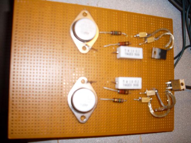
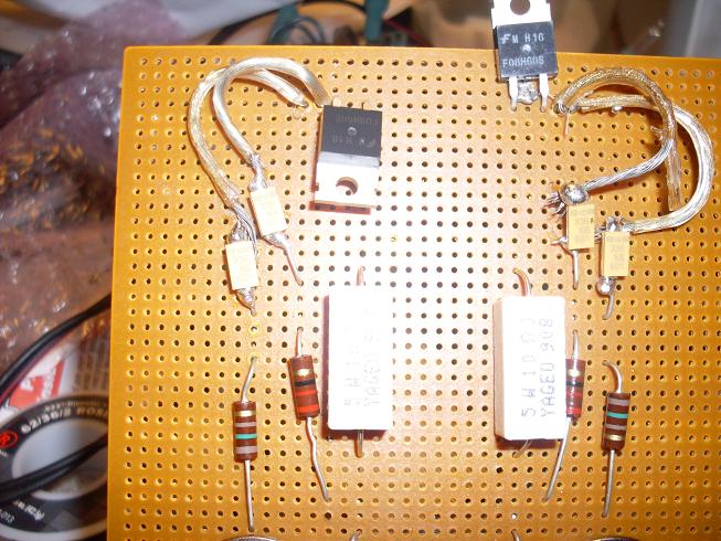
If I do the schematic at bottom of this thread but use these 220uF 400v photo capacitors, where do you think we will be? but but wait there's more audioguru check this http://www.electro-tech-online.com/alternative-energy/86777-grid-tie-inverter-schematic-3.html this guy is offering up free info at this other board on how to build grid tie inverters, he said he is putting together some DIY cd's showing how to do his grid tie inverters. The info he offered up is later on in that grid tie inverter forum. IDK, maybe you've see it already, but still cool none the less.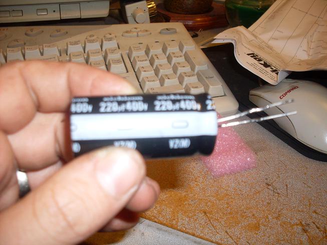
$19.95, it's no wonder, a capacitor and toothpic!
3) R3 and R4 still do not provide the transistors with enough base current.
I don't know about your battery, my batter has 7800 Watts stored. 12v and 650 amps on demand.
We are starting out with 650 cranking amps in a lot of batteries, I have read manuals for several dc to ac power inverters and have discovered that they start out with a draw of only 380 miliamps.
Starting with 12v and taking a path through these resistors I get using I=E/R I=12v/10ohm I=1.2 amps, I'm not saying that this is the only path that positive electron flow will occur.
4) D1 and D2 will short-circuit the transformer when the voltage at each end tries to rise to +23V.
What voltage would that be? This is a DC circuit, would you be making a reference to AC electricity that will have almost zero potential when dealing with a silicon diode.
5) R5 and R6 make no sense and would just reduce the current from Q2.
This circuit won't wait for these little guys, but somehow man does make the universe try to conform as to be of some use. If you want to, you can try and find another similarly rated component to do the job, if there is a such an animal. I took a 1000, what will you take, I suggest 1200, 1400, 1700, 2000, maybe 4700, 7000, 10000, 11000, none of that is proven though till we try.
6) The voltage rating of your capacitors is too low. In the original project capacitors C1 and C2 charge to about 23V. Use 50V capacitors.
Yes, there were two capacitors in Aaron's shematic, they were both rated at 60v. Let's see 60+60=120, I have provided 4 capacitors rated at 33v, so 33+33+33+33=132, I have more volts.
Using Ohm's law given half the resistance across the circuit and the circuit joined with every component of this circuit, this model shows above 50 volts.
Voltage 12 volts
Current 1.2 amps
Resistance 1 10 ohms
Power 14.4 watts
Voltage 46.475800154489 volts
Current 0.30983866769659335 amps
Resistance 2 150 ohms
Power 14.4 watts
Voltage 48 volts
Current 0.3 amps
Resistance 1+2 160 ohms
Power 14.4 watts
Voltage 51.1937496184837 volts
Current 0.28128433856309726 amps
Resistance1+2+3 182 ohms
Power 14.4 watts
5)
Besides jumping from an airplane, is there anything else? If it wasn't addressed you shouldn't mention it cause I'm on a tight budget here.
Go to Top of Page
Reply author: audioguru
Replied on: Apr 26 2009 09:57:53 AM
Message:
I copied a transistor multivibrator circuit that blinks LEDs. Its supply voltage is limited to 5V to avoid avalanche breakdown of the emitter-base junctions of its transistors . Thier emitter-base junctions have a max allowed voltage of 5V.
The 2N3055 power transistors in this inverter project have a max allowed emitter-base voltage of 7V so in my second schematic I added diodes in series with the emitters.
In my third schematic I have this inverter with diodes added in series with the emitters and protection diodes added differently to the collectors of the transistors.
The base current is only (12V - 0.8V)/180 ohms= 62mA. A 2N3055 transistor saturates pretty well if its collector current is 2A when its base current is only 62mA. Then the power from the battery is 12V x 2A= 24W and the output power from the inverter is a little less.
The 2N3055 transistors need driver transistors.
Download Attachment: 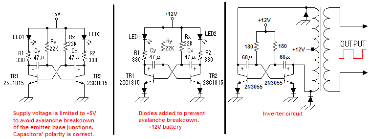 inverter circuit.PNG
18.66 KB
Reply author: audioguru
Replied on: Apr 26 2009 4:41:59 PM
Message:
Hi Dimestone,
Nobody sees anything good about your modifications that won't work.
This project was probably started about 50 years ago but used PNP germanium transistors which explains the backwards capacitors. Germanium transistors did not have a low voltage emitter-base avalanche breakdown.
Reply author: audioguru
Replied on: Apr 26 2009 6:03:14 PM
Message:
Hi Dimestone,
Never mind changing this hopeless inverter circuit around. If it is fixed then its output power is very low.
This is how it will work if it is fixed:
Download Attachment: 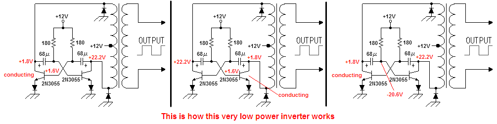 inverter circuit again and again.PNG
19.41 KB
Reply author: dimestone
Replied on: Apr 27 2009 04:41:34 AM
Message:
quote:
Originally posted by audioguru
Hi Dimestone,
Never mind changing this hopeless inverter circuit around. If it is fixed then its output power is very low.
This is how it will work if it is fixed:
Download Attachment:
19.41�KB
My momma told me since I can remember that I was the "Icing on the cake." I'm building a prototype at the moment, I have to let the iron warm up.
Reply author: Justinjustin
Replied on: May 18 2009 05:13:45 AM
Message:
quote:
Originally posted by audioguru
Hi Kennedy,
That 500W inverter had many mistakes. I fixed it two years ago but a moderator there recently changed it so it doesn't work any more. Here is my fixed one. For 1000W it needs many more transistors and 100A from the 12V battery. Its output is a square-wave.
Download Attachment:
161.27�KB
Hi, audio Guru,
this is the one I am using, I want to know the VArating of the transformer. and Can transformer use reverse?
Reply author: audioguru
Replied on: May 18 2009 6:38:27 PM
Message:
That is a very old inverter that was originally designed in China.
It uses many old 2N3055 transistors because modern Mosfets were not available there.
I fixed it so that it could be used in The Philippines where poor people do not have any electricity.
It has a square-wave output. Many electronic products do not work properly with a square-wave.
Sometimes a transformer can be used in reverse if it has enough inductance.
The output power is 500W so the transformer should be 600VA.
It was recently improved with a zener diode and a change in the transformer voltage.
Download Attachment: 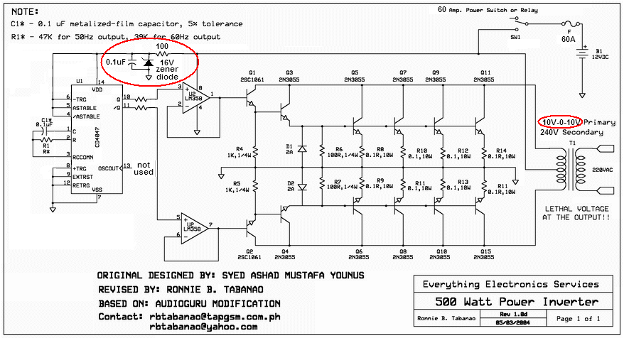 500w inverter final again.PNG
151.1 KB
Reply author: Dino_25
Replied on: May 20 2009 03:47:20 AM
Message:
I normally tinker around with simple RF receivers, low power TX, and audio-- inverters are fairly new to me. I thought I'd throw this piece of crap together to see what would happen. Well... It DID work... for about 30 seconds with a 75W bulb, then I found myself cleaning up electroylitic acid. I tried once more, but made various changes. I paralleled 2 more 3055's, added diodes in series with the transistor's bases with a couple of resistors to ground to turn the transistors off, and added some zener diodes in place of the 10 ohm resistors and diodes on the xfrmr. It helped a little. I ran a 75 watt bulb for a whole 1 min, 30 secs before it died. So I scrapped it.
Later, I read about an even simpler inverter circuit by Harry Lythall. Here's the link to the article http://web.telia.com/~u85920178/. I was skepticle, so I threw the thing together, powered it up, and heard the old familiar buzz. I conneted two 20watt flourescent bulbs and the thing worked. I left it on for about 30 minutes with no problems. The transistors actually didn't get that hot with no heatsink at all, but I connected a small fan to blow cool air on them just to be sure. I wouldn't dare try and connect my laptop to it though.
I CAN say, however, that the circuit on aaron's site works... for a few seconds, followed by explosions. Maybe there are ways to improve it (like audioguru suggested), but it would just be too much of a headache. For anyone who is looking for a permanent power back-up, just buy a cheap inverter off ebay or find a better designed circuit to work with. Or if you have a couple of uninteruptable power supplies (UPS), like I do, they work just fine. I have 2 small APC BK400 250W UPS's. I found them at a thrift store for $2.00 a piece![]() !!! I use one to power a small 55 watt tv and playstation during outages.
!!! I use one to power a small 55 watt tv and playstation during outages.
I would go for audioguru's redesigned 500W inverter. It looks like a great circuit. And if anyone has difficulty find the CD4047 IC, jameco.com has them for about $0.29 a piece.
Reply author: Dino_25
Replied on: May 20 2009 03:50:47 AM
Message:
Sorry about the Jameco link... I must've screwed up. It should be easy enough to just enter www.jameco.com into your browser.
Reply author: Alberto
Replied on: Jun 29 2009 8:27:14 PM
Message:
I guess I joined too late. I�ve been reading this topic and replies from the start and the more I read the more I get confused. That�s just because Me ( and anybody who joins late ) doesn�t know WHICH schematic ALL of you are rfering to. So, why can�t everybody attach their schematic when you post, either a questio or an answer. Thanks.
Reply author: Alberto
Replied on: Jun 29 2009 9:07:59 PM
Message:
Sorry, everybody. I guess I posted when I shouldn�t. I started reading this thread from the BEGINNING.
Although I did SMILE and LAUGH sometimes, I�m getting more confused. I try to solve my problems by myself before, read all threads and posts and then ask my SPECIFIC questions. But it seems that a lot of us could go crazy if we�re not sure about WHICH schematic we are discussing: The original, rvised, corrected, functional, etc.
I strongly advise that whenever you post refer to THE schematic you�re talking about. I hoe this helps EVERYBODY!
Reply author: audioguru
Replied on: Jun 30 2009 8:31:49 PM
Message:
This thread is about the inverter circuit that has the polarity of its capacitors backwards so they blow up.
It also has the max allowed emitter-base voltage of the transistors exceeded so they also blow up the capacitors even if their polarity is correct.
The base current of the transistors is much too low so that they need driver transistors.
The circuit is a joke.
Reply author: Alberto
Replied on: Jul 01 2009 5:36:59 PM
Message:
Excuse me audioguru. I�m going through this thread from the beginning ( 2004 ) and the forum mentions too many schematics. Anyway, have you ever discussed this one. If so could you direct to where it began. If not, how about your opinion and any suggestions. Thanks.
Download Attachment: 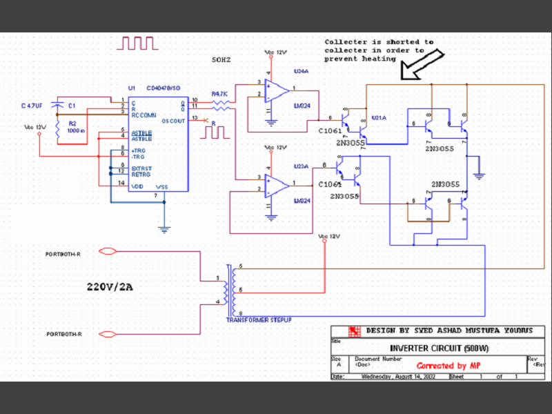 New Drawing.PNG
147.62 KB
Reply author: audioguru
Replied on: Jul 02 2009 09:24:58 AM
Message:
Hi Alberto,
The circuit you found was "corrected by MP" but he made many errors:
1)It doesn't have enough output transistors for 500W output. Each 2N3055 output transistor has an absolute max allowed current of 15A but performs poorly above 10A. But with a 500W load each output transistor must pass 25A.
2) Its 2n3055 transistors must be matched.
3) There are no protection diodes to arrest voltage spikes.
4) The resistor R2 in the CD4047 oscillator is only 1k ohms but Texas Instruments says it should be a minimum of 10k.
5) The timing capacitor in the CD4047 oscillator is way too high at 4.7uF and a low tolerance capacitor cannot be found with such a high value.
6) It doesn't have a fuse to stop a fire.
7) It uses two LM324 quad opamps instead of just a single LM358 dual opamp.
8) Its output is a square-wave without voltage regulation.
9) It does not shut down when the battery voltage gets low.
I fixed it and it is used in 3rd-world countries. It would be much better if a Mosfet circuit replaced the 2N3055 transistors but Mosfets are rare in 3rd-world countries. It would also be better if gates were added to make it have a "modified sine-wave" output waveform. We discussed the gates, shutdown when the battery gets low and even discussed voltage regulation in this and other threads.
Here is my fixed version of the 500W inverter:
Download Attachment:  500W inverter final.PNG
86.17 KB
Reply author: albertok
Replied on: Jul 07 2009 11:05:14 AM
Message:
quote:
Originally posted by audioguru
3000W is way too much for an inverter. If you use only 12V then its battery current will be 300A!
You would need to have a large room full of batteries to power it for a short time. Then it will take 1 week the charge the batteries.
Its wiring must be huge and it would need 48 output transistors and many driver transistors.
Its transformer would cost a fortune.
Why do you keep saying that it's not possible to make an 12V 3000W inverter? And that you would need a room full of batteries?? It simply is not true and you know it.
A well built 12V 300W inverter consumes about 300A at full load give or take. Well, that said I think you would agree with me that it's not impossible nor dangerous to take 55 Amps out of a small vehicle 55Ah battery, right? Neither is it any more danger involved in taking off 300Amps from a 300Ah battery, (given you know what you're dealing with), it CAN KILL YOU, but not because the battery is programmed to explode like you try to scare people with. So you probably should stack up with a couple of heavy duty 230Ah batteries.
3000W inverters have been around for a long time running on 12V, but given the high amperage you're dealing with it's more than twice as dangerous as a 3000W 24V inverter.
Reply author: albertok
Replied on: Jul 07 2009 11:11:34 AM
Message:
Furtermore it's worth to say about heavy cables and large inverters that for any 12V invertes from a few hundred watts and up, it is absolutely nessesary to keep cable lenghts to a minimum. Unless you have a wery deep wallet :)
Reply author: audioguru
Replied on: Jul 07 2009 3:09:10 PM
Message:
A battery rated at 300Ah is tested with a 30A current, not 300A.
Cold Cranking Amps are tested for a very short duration.
Reply author: albertok
Replied on: Jul 07 2009 4:14:22 PM
Message:
I'm not talking about CCA, I'm talking bout if there is a chance for a battery to blow up when you draw from it Amps in the range of its rated Ah capacity. It will not. I have never had any of my approx. 55Ah car batteries that's been fitted to my car blow up even when I draw up to 200 Amps. 30 Amps run just by turning the key, another 75 - 150 when I crank it. Comes close to 200. When that's said I'm also aware of it's intended purpose, and the fact that you'd drain it extremely fast. But for testing purposes it's close to ideal because you get quick response from the battery when you test your low voltage cut-off, and voltage regulator. You just turn off your charger and voltages drop fairly quick.
Also something I forgot to mention earlier is the main reason many people buy 3000W inverters in the first place. Some just want to be able to run 1000W power-tools for a few seconds at a time now and then, some want the convenience of haveing a microwave owen in their trailer, boat or cabin. Most do not intend using its full rated power for an extended period of time.
Reply author: antish
Replied on: Aug 20 2009 2:48:23 PM
Message:
i have a problem in 12/24vdc input to 220/230vac output with 4000w and above.please help me to do that
Reply author: superchad
Replied on: Oct 30 2009 4:32:06 PM
Message:
hi i saw this simple inverter when googling schematics for and inverter, i saw that it might have problems, well i need to know what would best for me, i need to make an inverter that is about 75 Watts to 100 Watts (for using a laptop in a car) i want it to be as simple and cheap as possible. thanks in advance.
Reply author: audioguru
Replied on: Oct 31 2009 12:16:01 PM
Message:
This week, Canadian Tire store is selling a Name-brand 150W inverter for $19.99.
It would cost about $60.00 to make one.
They also have an 800W one on sale for $59.99.
Reply author: superchad
Replied on: Oct 31 2009 5:19:14 PM
Message:
i estimated the originaly circuit aaron posted at around $20 to $30 to make (for the parts) i want to make one someday so id like to have the link to schematic for one.
Reply author: audioguru
Replied on: Oct 31 2009 8:36:31 PM
Message:
The inverter here does not work.
You can make a simple square-wave inverter that does work (but poorly) for the same low cost.
Reply author: 00milind
Replied on: Nov 01 2009 01:31:41 AM
Message:
Looking for a pure sine wave inverter design, 48V to 240V, 50Hz, if anyone can help I would appreciate it.
Reply author: Darkthero
Replied on: Nov 04 2009 03:48:38 AM
Message:
i didnt take time to read all the above posts but i have posted a pic of the circuit . i have made changes, and it dose work this way. i got it sitting next to me running as i type this. notice the caps. and yes Tantalum caps do have a polarity. http://img522.imageshack.us/img522/952/inverter.gif
Reply author: Darkthero
Replied on: Nov 04 2009 03:50:30 AM
Message:
dont ask why im not entirely sure why. but i accidentally placed them like this and it functions
Reply author: Darkthero
Replied on: Nov 04 2009 05:37:48 AM
Message:
http://img522.imageshack.us/img522/952/inverter.gif
Reply author: audioguru
Replied on: Nov 04 2009 3:33:23 PM
Message:
quote:
Originally posted by Darkthero
dont ask why im not entirely sure why. but i accidentally placed them like this and it functions
You corrected the error of the backwards polarity of the capacitors.
But you did not correct the error where the transistors have avalanche breakdown when the capacitors try to drive the bases to -23V (the max allowed voltage is only 7V). The avalanche breakdown causes extremely high currents in the capacitors that causes them to explode even when their polarity is corrected.
You also did not correct the error where the base current for the transistors is much too small.
Reply author: Darkthero
Replied on: Nov 04 2009 4:04:52 PM
Message:
quote:
Originally posted by Darkthero
i didn't notice those. but the way i have it now its putting out 130v and low amps and my caps havent exploded yet
Reply author: audioguru
Replied on: Nov 04 2009 9:25:30 PM
Message:
An inverter that puts out low amps is useless.
I think it wastes most of its battery power.
It is easy to modofy the circuit so that the transistors do not have avalanche breakdown. But then the base current for the transistors will still be too low.
Reply author: Cokaric
Replied on: Dec 25 2009 06:39:21 AM
Message:
I am building ur Inverter base on this...
http://electronics-diy.com/electronic_schematic.php?id=605
I have Googled for last hour or two and finally found ur original schematic... My English lng is poor so I mostly cant understand English electronic terminology.
What I want >>
I want to build ur Inverter, I need to power my computer with it when there is no power, my professor says, with 100 Amph Accumulator it will power my computer for about 8 h, in theory 40 h, but then after I can trow battery.
What battery should I use, what transformer should I use. My grid is ~230V/50Hz. How to modify this schematic to build a 1 kW Inverter. I have 500 W power supply in my computer, what would happen if I connect my computer on 1kW Inverter...
Please can u give me ur email or some way I can contact u... What lng except English do u speak ?
Best regards,
Cokaric
Reply author: audioguru
Replied on: Dec 25 2009 10:36:21 AM
Message:
My inverter circuit was originally designed in the Orient for 3rd world countries. It didn't work so I fixed it. It is very simple so it produces a square-wave output that many electronic products do not use, and it does not have voltage regulation so its output voltage is too high with a light load or fresh battery charge and its output voltage is too low with a full load and when the battery has run down.
My 500W computer does not draw 500W all the time, only when it is crunching many numbers. Usually its power is about only 50W.
I speak only English.
Reply author: weqwedas
Replied on: Dec 26 2009 01:27:32 AM
Message:
Well seeing as how you're still answering questions, I might as well ask a few of mine. I have been attempting to build an inverter to understand the concept for quite awhile now. I attempted to use both a dual-transistor flip-flop as well as the CD4047 circuit (looks almost exactly like the new light duty inverter circuit you have listed here, but with no amplifiers and a 5.1 volt Zener diode across the CD4047). Both times, however resulted in the flip-flop freezing up and dumping as much current as the 9 volt battery could through one transformer as well as the transistor that was in series with it. It was only after using two 9 volt batteries (one to power the CD4047, one to power the transformers) that I was finally able to get it to work. I noticed that because all of the current was going through the transformer, the CD4047 wasn't able to function correctly (at least that is what I can observe). Finally to the questions:
1. Could this possibly be due to the fact that I am using a 9 volt battery which cannot provide nearly enough current as a car battery?
2. Would adding the two amplifiers make the circuit more efficient or solve the previous problem? What are they there for exactly in your circuit?
3. Is it possible to run it off of a single voltage source without having the CD4047 deprived of amperage?
That should be all for now. If you need clarification on anything, I'll read it later on today.
Reply author: audioguru
Replied on: Dec 26 2009 11:18:38 AM
Message:
quote:
Originally posted by weqwedas
I attempted to use both a dual-transistor flip-flop as well as the CD4047 circuit (looks almost exactly like the new light duty inverter circuit you have listed here, but with no amplifiers and a 5.1 volt Zener diode across the CD4047).
Both times, however resulted in the flip-flop freezing up and dumping as much current as the 9 volt battery could through one transformer as well as the transistor that was in series with it.
Post your schematic here so I don't need to guess about it.
An inverter output is hundreds of Watts. A little 9V battery can supply only 2.2W for about 10 minutes.
Download Attachment:
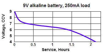 9V alkaline, 250mA load.PNG
8.28 KB
Reply author: weqwedas
Replied on: Dec 26 2009 3:23:20 PM
Message:

This one was the original which constantly locked up.
This one is the one that works. The concept was not really meant to power anything, just charge a capacitor. The 45 ohm resistors could probably be moved to the transformer battery side without any complications. It was modeled after the disposable camera circuits in an attempt to charge the capacitor faster.
(Edit) Hmm I just noticed that the zener there is not actually doing anything in that circuit. There used to be a 100 ohm resistor in between B2 and D1. I'll have to add that back in.
Reply author: audioguru
Replied on: Dec 26 2009 8:08:28 PM
Message:
It is not a mains inverter. It makes a high voltage for a zapper or something. the transistors are not flip-flops. The first little ones are emitter-followers driving the larger ones that are common-emitter switches.
The circuit with only one battery has the battery being killed by the high current in the TIP31 transistors that stops the CD4047 oscillator.
The circuit does not need the zener diode since the max allowed supply for the CD4047 is 18V. The CD4047 has a typical output current of only 4ma when its supply is 5.1V. Its output current is 22mA when its supply is 12V.
Since a little 9V battery is very weak then the supply should have a parallel supply bypass capacitor of about 100uF.
Reply author: Cokaric
Replied on: Dec 26 2009 8:21:51 PM
Message:
@audioguru
I was reading from page 1 so I dint saw schematic on page 54, http://www.aaroncake.net/forum/uploaded/Audioguru/20097292438_500W%20inverter%20final.PNG
Can u tell me what is F and what is SW1, I really don't know, I suppose that SW1 is switch and F relay but I am not sure. SW1 is switch does it need to be 60 A. Or maybe is SW1 relay and F fuse? What should be cross section of conductors. What should be cross section on PCB? What battery would u advise me to use?
Did u applied any other changes in ur inverter, did u improved anything and can u post here, please, if u did?
What do u think about this inverter, is MOS-Fet better or urs?
http://electronics-diy.com/electronic_schematic.php?id=609
My professor is sure that urs will work but for this one he said that no1 in our school build it before so he doesn't know if it would work.
I will continue posting in this thread thoug next few weeks, hope I wont disturb u much... Thank u for ur support =)
Best Regards,
Cokaric
Reply author: weqwedas
Replied on: Dec 26 2009 8:42:26 PM
Message:
quote:
Originally posted by audioguru
It is not a mains inverter. It makes a high voltage for a zapper or something. the transistors are not flip-flops. The first little ones are emitter-followers driving the larger ones that are common-emitter switches.
The circuit with only one battery has the battery being killed by the high current in the TIP31 transistors that stops the CD4047 oscillator.
The circuit does not need the zener diode since the max allowed supply for the CD4047 is 18V. The CD4047 has a typical output current of only 4ma when its supply is 5.1V. Its output current is 22mA when its supply is 12V.
Since a little 9V battery is very weak then the supply should have a parallel supply bypass capacitor of about 100uF.
The flip-flop circuit I was talking about was superseded by the CD4047 chip. What I'm asking is what makes your circuit work where as my circuit freezes? Does the amount of current a car battery can provide mean the difference between oscillating and locking up?
Reply author: audioguru
Replied on: Dec 27 2009 12:59:25 AM
Message:
I have never played with the transformers from a camera's flash so I don't know how much current the transistors will use driving them.
I do know that the current from a little 9V battery is low so that each time the transistors conduct the battery voltage will drop maybe low enough to stop the CD4047 oscillator.
Maybe the frequency of the CD4047 is too low for the little transformers.
A camera's flash unit doesn't use a weak little 9V battery but uses two powerful AA cells instead. Also, the flash unit's transformer is designed for a 3V power supply, not 9V that will increase the current that is used.
In my 500W inverter, SW1 is the on-off switch and F is a 60A fuse to stop a fire if something shorts.
The car battery can supply 500A before its voltage drops and look at the difference in its size and weight compared to a little 9V battery.
Gary's inverter also has a simple square-wave output but it is too complicated. I would use a CD4047 to drive the Mosfets.
Reply author: wasssup1990
Replied on: Dec 27 2009 02:08:45 AM
Message:
I remember playing with High Voltage siren flashes and camera flashes when I was just a few years old. Going by the sounds they made to charge up those capacitors I would have to say that the camera flash transformer spent most of its time above 2KHz and the siren flasher about 10KHz. I can understand why the siren flasher operated at a higher frequency. The flash interval was short and the transformer was small meaning that the energizing period would have to be shorter since the small transformer coil couldn't store too much energy in a single cycle from its drive circuitry. If the transformer coil was larger (could store more energy) then the drive circuitry could operate at a lower frequency. If the frequency is to low it will be audibly annoying, if it is too high you will need more expensive transistors that have shorter rise and fall times to be efficient but you would be able to flash the Xenon gas tube more frequently.
I hope this becomes useful to someone.
Reply author: weqwedas
Replied on: Dec 28 2009 10:29:58 PM
Message:

(Borrowed from http://www.repairfaq.org/sam)
This inverter, based off of the disposable flash camera, worked incredibly well, charging the capacitor to 300 volts in only a few seconds. It used the same transformer as my last circuit and only one 9 volt battery with the only different component being the 2sd2504 transistor used for its high gain. Only problem with this circuit in particular is it's DC only, which means you'd have to have a DC-AC circuit in order to use it for AC purposes.
Reply author: wasssup1990
Replied on: Dec 28 2009 11:55:02 PM
Message:
Yep I did a very similar experiment many years ago. I was able to use a camera flash circuit to power some small home appliances off a rechargeable cell phone battery. I enclosed it all in a self made wooden box and used it for experimentation. It has the potential to stop your heart and cause severe burns if you are caught between the capacitor terminals which is what you should be aware of. You should keep it away from people who are ignorant in this field. They could pick up your circuit and wonder "oh what is this" and then BANG. I have been shocked many times by all kinds of power supplies and I'm still here, but just be carefull. ![]()
Reply author: Ibrahim
Replied on: Jan 04 2010 03:55:23 AM
Message:
please i need sinewave inverter schematic circuit daigram
Reply author: audioguru
Replied on: Jan 04 2010 11:45:40 AM
Message:
A sinewave inverter is fairly complicated. You probably cannot obtain the modern parts it needs in Africa.
Reply author: sparkie
Replied on: Jan 15 2010 10:02:36 PM
Message:
Hiya all.
After looking through this thread and the internet and building a few of the circuits I found, I came up with one of my own using a PIC microchip. I havent tried it at a few hundred watts as yet, but I think it will be OK up to about 500w if you have a transformer and battery big enough.
More info on this circuit is here: http://www.m0ukd.com/electronics/modified_sine_wave_inverter/
I would be interested to know if anyone tries it how they get on!
Cheers, John. ![]()

Reply author: Ibrahim
Replied on: Feb 05 2010 04:27:03 AM
Message:
pleas help me i am 17 years old i do electronic work i need 1000 watt inverter circuit diagram that will work faine pleas help me goodby see your messsage thinks
Reply author: audioguru
Replied on: Feb 05 2010 10:30:10 AM
Message:
Everybody in Nigeria needs an inverter.
Where are you going to buy a huge and expensive transformer and many Mosfets?
Where are you going to find a huge and heavy battery that runs 1kW for only half an hour?
Reply author: weqwedas
Replied on: Feb 08 2010 7:33:16 PM
Message:
Ibrahim:
A little known fact is that the human body makes a great inverter! All you need is a car battery, a person, and two sets of jumper cables. Hook up the parts like so:
Don't forget the battery polarity! This is important for the organic diodes. Please note that the jumper cable clamps and the voltage surging through the person may be a little uncomfortable at first, but that feeling will go away in a minute or two. If hooked up correctly, the two butt cheeks will begin to alternate contractions. This means that the body has converted the DC into AC successfully! Good luck!
Reply author: wasssup1990
Replied on: Feb 08 2010 10:55:17 PM
Message:
Be careful some people might actually beleive you and try this. But a good joke anyway.
PLEASE ME NEEDA THE HELP WIT FIVE 1000000000 WHAT INVENTNER!
Reply author: weqwedas
Replied on: Feb 10 2010 7:53:16 PM
Message:
I figured at that point it would be a matter of natural selection.
Reply author: wasssup1990
Replied on: Feb 10 2010 11:34:16 PM
Message:
Ha! Yeah. That's a little harsh but that's one way it works.
Reply author: Aaron Cake
Replied on: Feb 13 2010 10:49:39 AM
Message:
So after 55 pages, I think it might just be time to close this thread, but leave it as a sticky.
Thoughts?
Reply author: pebe
Replied on: Feb 13 2010 10:55:38 AM
Message:
I agree.
Reply author: wasssup1990
Replied on: Feb 13 2010 8:17:53 PM
Message:
Aaron... Do it. ![]()
Reply author: weqwedas
Replied on: Feb 15 2010 12:13:09 AM
Message:
If you can, edit the first post to say that the schematic that links to this thread is very faulty.
Reply author: smeezekitty
Replied on: Apr 08 2010 9:52:06 PM
Message:
Is it me or are the caps backwards on the diagram O_o.
Reply author: Cokaric
Replied on: Apr 11 2010 10:19:08 AM
Message:
Well last time I contacted u was about 4 months ago, in the meantime I examen many circuits but I stick with urs... well PCB is finish now, but I need to ask u few q before I start building it...
#1
Could u check my design ?
#2
Is it possible to modify it for higher power, like 750 W, 850 W or 950 W?
#3
With 500W and 45 Ah battery and consumption of 2,18 Ah in theory it can provide electricity for 20,64 h but I am sure that I would feel effects after only 8h. Is this correct ?
#4
What should be boards copper thickness ?
#5
How wide should lines be, 4 mm ?
Best regards,
Cokaric
Reply author: audioguru
Replied on: Apr 11 2010 1:13:49 PM
Message:
quote:
Originally posted by Cokaric
Well last time I contacted u was about 4 months ago, in the meantime I examen many circuits but I stick with urs... well PCB is finish now, but I need to ask u few q before I start building it...
#1 Could u check my design ?
#2 Is it possible to modify it for higher power, like 750 W, 850 W or 950 W?
You forgot to attach your schematic and parts list so we don't know what you are talking about.
quote:
#3 With 500W and 45 Ah battery and consumption of 2,18 Ah in theory it can provide electricity for 20,64 h but I am sure that I would feel effects after only 8h. Is this correct ?[/quote]
A 500W inverter is about 80% efficient so it draws a max of about 625W from the battery which is a current of 52.1A. If the battery current is only 2.18A then the power output is zero since the inverter has an idling current from the battery of more than 2A.
A 45Ah battery supplies 4.5A for 10 hours or 45A for about 15 minutes. It might overheat and boil if it supplies 45A for more than a few minutes.
Reply author: Cokaric
Replied on: Apr 12 2010 06:26:55 AM
Message:Sorry, I was talking about ur schematic but it seems I didn't express my thoughts well so u were unable to understand me... sorry again...
Ur Desing >>
Download Attachment:
86.18 KB
PCB >>
Download PNG PCB:
31.48 KB
Download PCB:
9.56 KB
In PCB I used 0,22Ohm 5W resistors to get 0,11Ohm 10W resistors
In the middle is circle that goes to Emiter of 2N3055 Transistor, his collector is cooler where they are all attached, Base is manually connected with wire from one Transistor to other...
IC CD4047 leg one is down left connected to C1 parallel to R1, leg 4,5,6 & 14 goes to R100 and he is connected to 0 on transformer
ICLM358 leg one is down right connected to base of 2SC1061, legs 6&7 are connected to jumper that goes to base of 2SC1061, leg 8 is connected to 0 on transformer
I order 2SC1061 but they sent me simillar one whos legs are Base, Collector in middle, Emiter...
This is basic, I will draw with my hand elements and re upload picture here...
This has been done in program called PCB Artist
Regards,
Cokaric
Reply author: audioguru
Replied on: Apr 12 2010 08:40:19 AM
Message:
quote:
Originally posted by Cokaric
#1
Could u check my design ?
What do you want to be checked?
This very simple circuit was designed for 3rd-world contries where modern Mosfets and PWM iCs are not available. It has a crude square-wave output.quote:
#2
Is it possible to modify it for higher power, like 750 W, 850 W or 950 W?
It is not practical to add more driver and output transistors. A single battery will boil or melt anyway due to the very high current.quote:
#3
With 500W and 45 Ah battery and consumption of 2,18 Ah in theory it can provide electricity for 20,64 h but I am sure that I would feel effects after only 8h. Is this correct ?
I don't know how many amps it draws from a battery when it has no load.
Reply author: Aman2009
Replied on: May 06 2010 02:42:06 AM
Message:How to simulate this circuit diagram in the electronic workbench
Reply author: pebe
Replied on: May 06 2010 04:00:15 AM
Message:I don't know of the simulator 'electronic workbench', but did it not come with a set of instructions or a Helpfile?
Reply author: audioguru
Replied on: May 06 2010 5:14:04 PM
Message:A simulation program will show you that the simple square-wave inverter's output voltage is not regulated and will be too high when the battery is charged and the load current is low and the output voltage is too low when the battery is running down and the load current is high.
The sim program might show its awful square-wave output waveform that will not power modern electronic products because it does not have the same high peak voltage of the mains sine-wave.
Reply author: Tinkerboy
Replied on: Jun 26 2010 09:22:21 AM
Message:I'm trying to build a high-wattage inverter, as well as some type of threshold-relay switch, in order to run my whole house on my 7kw generator, by using its starter-battery to supply the temporary impulse-current responsible for power-requirements above 7kw. If I can make a 10kw or more inverter, as well as a threshold-switch so that it only kicks on above 7kw, then the battery should have enough cranking-amps that there will be no problem supplying the few seconds of impulse-current to get things started (like lights, televisions, microwave etc), since my house rarely requires more than a two steady-state kilowatts at a time, and never more than five. Rather, it's the impulse-current that requires the more heavy-duty 15-20 kw generators to run a whole house. Likewise, the generator already has a function to re-charges the starter-battery.
Do any pro's have any ideas about this? Thanks.
Reply author: yashkhaitan
Replied on: Jul 26 2010 12:37:44 PM
Message:Can someone please tell me what is the quiescent power consumption of this circuit (12VDC to 220VAC)?
Reply author: audioguru
Replied on: Jul 26 2010 1:44:12 PM
Message:
quote:
Originally posted by yashkhaitan
Can someone please tell me what is the quiescent power consumption of this circuit (12VDC to 220VAC)?
Which circuit are you talking about?
Reply author: vinu673
Replied on: Feb 19 2011 06:27:12 AM
Message:hello ,
Iam planning to make 2000W 240 V (to work with 1600 W normally) inverter driven from 110 V 75 AH battery , can any body help me by sharing some circuits and experience , is there any idea to limit input current TO 15 A?
vinu673
Reply author: Aaron Cake
Replied on: Feb 19 2011 10:26:32 AM
Message:Why don't you read through the topic and look at all the circuits posted? The hardest part is going to not be the driver circuit (many examples in this thread) butthe custom 1:2 transformer. Probably start with a huge microwave transformer and wind on a new secondary.
Reply author: Waqas
Replied on: Apr 07 2011 06:27:42 AM
Message:Please tell me how can i make a simple 50Hz 220v suply with 12V battery
Reply author: audioguru
Replied on: Apr 07 2011 6:59:47 PM
Message:Simple means very poor performance or no performance.
A simple inverter can light an incandescent light bulb or heater.
But many electronic products won't work.
Where will you buy a powerful deep discharge battery? A car battery is designed to deliver very high current for a few seconds and will be destroyed if it is used to power an inverter.
Reply author: Aaron Cake
Replied on: Apr 09 2011 10:26:57 AM
Message:
quote:
Originally posted by Waqas
Please tell me how can i make a simple 50Hz 220v suply with 12V battery
If you review this topic in which you just posted, you will see many such schematics have been posted already. That's why this topic is a sticky topic; because inverter questions come up all the time.
Reply author: vinu673
Replied on: Jun 14 2011 07:39:28 AM
Message:is 110v dc 230v ac inverter is possible with a current control on input side?
pl help
Reply author: vinu673
Replied on: Jun 14 2011 07:41:53 AM
Message:1500-2000 w power?
Reply author: Aaron Cake
Replied on: Jun 18 2011 10:25:47 AM
Message:Not with the schematic shown on the inverter page. There are several schematics posted in this thread which could handle that much power but the output section and transformer would be huge. An inverter in the 2KW range really should be a switching supply, and such a power supply isn't made from commonly available parts.
Reply author: Ferraro1
Replied on: Jul 27 2011 02:59:29 AM
Message:AH! But this circuit does work!!! I am having some problems with frequency here, so I will attempt to alter the RC network a little. Tantalum capacitors are hard to find in the denominations were using here, might have to parallel a bunch up. I do see the reason for tantalum caps here, at the cost of several electrolytic explosions. :) I did scope the output on a digital o scope and there sure is a bunch of high frequency crap, might try a little low-pass and see if I can't reject some of it. Wanted to mention also that I wired a 12.6V CT XFMR rather than the 24v as shown, and of course at the cost of output current, but with the 3055 nPn s I'm using it could be upgraded easily with either a hand wound XFMR or a salvaged one. I'll let you know just how much I can push out, also consider using an in line fuse here. Thanks for thus we're going to go with a solar application for this.
Reply author: audioguru
Replied on: Jul 28 2011 08:09:21 AM
Message:The capacitors blow up because they have the very high current of the transistors having avalanche breakdown of their emitter-base reverse biased junctions in them. The avalanche breakdown causes most of the power to be wasted (which blows the capacitors) so the remaining output power is very low. The transistors have a forward base current that is too low to make much power anyway.
Silicon transistors should never be used in this multvibrator circuit when the supply is higher than 7V to eliminate avalanche breakdown (or maybe re-designed with extra diodes). Maybe this circuit originally used old germanium transistors.
Reply author: pebe
Replied on: Jul 28 2011 12:55:52 PM
Message:
quote:I have found tantalums available up to 200uF. But tants are polarized, so what makes you think they will stand reverse voltage better than electrolytics?
Tantalum capacitors are hard to find in the denominations were using here, might have to parallel a bunch up. I do see the reason for tantalum caps here, at the cost of several electrolytic explosions
Reply author: audioguru
Replied on: Aug 22 2011 2:51:01 PM
Message:The polarity of the capacitors has been recently corrected on the schematic.
Their polarity is reversed only about 0.6V which will not damage an electrolytic capacitor.
But there is a very high current in the capacitors that damages them. One capacitor is charged to about 24V (transformer action causes a transistor collector to swing to +24V) then this transistor turns on and its collector saturates and drives the positive end close to ground which tries to drive the negative end to -24V. But the emitter-base junction of this transistor has avalanche breakdown (like an 8V zener diode) at a high current. The high current is in the capacitor.
The avalanche breakdown of the emitter-base junctions can be prevented by adding diodes in series with each base. Then each base will need a 2.2k resistor to ground to make it turn off when it should be turned off.
The timing will need to be re-adjusted.
The base current is low so the output power will be low.
Download Attachment:
6.96 KB
Reply author: JUAN DELA CRUZ
Replied on: Aug 23 2011 06:05:16 AM
Message:@audioguru
Hi audioguru! Its been a long time :-)
Do the inverter circuit above (with the correction) is functioning now?
How much power it can provide from a 100AH car battery?
Reply author: audioguru
Replied on: Aug 23 2011 11:26:27 PM
Message:Hi again, Juan.
My corrections to the inverter will result in a base current of only about 66mA. Then the transistor collector current will be only 660mA if the transistors have minimum current gain when saturated.
660mA at 120VAC output is a power of only 79.2W. Some transistors with a high current gain might provide an output power of 158W.
The extremely simple circuit produces a square-wave output that many electronic devices cannot use.
Its output voltage is not regulated so it is too high with a freshly charged battery and light load and is too low when the battery is running down and the load is heavy.
Reply author: JUAN DELA CRUZ
Replied on: Sep 01 2011 1:35:22 PM
Message:Well it is a good choice for low power application where in voltage regulation is not the priority.
BTW, what is transistor that can be use to increase its output power a little bit? (that you have mentioned with High Gain?)
Thanks audioguru
Reply author: audioguru
Replied on: Sep 02 2011 09:28:36 AM
Message:
quote:
Originally posted by JUAN DELA CRUZ
BTW, what is transistor that can be use to increase its output power a little bit? (that you have mentioned with High Gain?)
Hi Juan,
Inverters used power transistors many years ago. Today they use a little oscillator that drives power Mosfets.
Reply author: JUAN DELA CRUZ
Replied on: Sep 04 2011 5:49:51 PM
Message:http://www.edaboard.com/thread192166.html
Please click the link. (on the lower part of the discussion)
Guys, please assist me here.
I need to drive a power mosfets instead of BJT in the PWM inverter circuit (in the LINK)
What will be the change needed? I wiill be using a deep cycle batteries For approx. 1KW output.
Thanks.
Reply author: pebe
Replied on: Sep 05 2011 11:44:36 AM
Message:I think the designer must be living in Dreamland if he thinks he can get 5KW out of that output stage.
Reply author: JUAN DELA CRUZ
Replied on: Sep 05 2011 12:27:12 PM
Message:
quote:
Originally posted by pebe
I think the designer must be living in Dreamland if he thinks he can get 5KW out of that output stage.
Hi Pebe its been a long time!
Yeah I think the designer used a bank of batteries! 5Kw output is impractical due to losses using BJTs.
I was looking for just approx. 1Kw output from a Deep cycle batteries.
I need to drive a Power Mosfets instead of BJT.
Do you think the driver ckt. (in the LINK) can drive power mosfets? What wiill be the adjustment needed?
Please assist me.
Thanks.
Reply author: audioguru
Replied on: Sep 05 2011 12:47:36 PM
Message:Most power Mosfets need a gate to source voltage of 10V to completely turn on.
That circuit has the IC powered by only 8V and it has losses so the gates of Mosfets will not be fed enough voltage.
Reply author: JUAN DELA CRUZ
Replied on: Sep 06 2011 11:46:02 AM
Message:
quote:
Originally posted by audioguru
Most power Mosfets need a gate to source voltage of 10V to completely turn on.
That circuit has the IC powered by only 8V and it has losses so the gates of Mosfets will not be fed enough voltage.
So, the IC should be powered by at least 12V regulated or higher to drive power mosfets?
How about the driver section.. is there any adjustment needed?
Thanks.
Reply author: audioguru
Replied on: Sep 07 2011 12:07:59 AM
Message:The SG3524 IC drives bipolar junction transistors very well but drives Mosfets poorly.
Complementary emitter-followers can be added to drive Mosfets but they produce additional gate voltage loss.
Reply author: JUAN DELA CRUZ
Replied on: Sep 08 2011 04:58:43 AM
Message:
quote:
Originally posted by audioguru
The SG3524 IC drives bipolar junction transistors very well but drives Mosfets poorly.
Complementary emitter-followers can be added to drive Mosfets but they produce additional gate voltage loss.
Ok, so complementary emitter-follower is needed in the drive section. But, using IT gate voltage loss is added? Why is that?
Can you show how it can be attach to the driver ckt?
Reply author: audioguru
Replied on: Sep 08 2011 1:54:06 PM
Message:A complementary emitter-follower has a 0.7V loss when it goes high and a 0.7V loss when it goes low.
The output of an SG3524 needs a pullup resistor then it can drive the complementary emitter follower. The complementary emitter follower can provide plenty of current to quickly charge and discharge the high gate capacitance of a Mosfet.
Download Attachment:
14.12 KB
Reply author: JUAN DELA CRUZ
Replied on: Sep 08 2011 6:05:26 PM
Message:
quote:
Originally posted by audioguru
A complementary emitter-follower has a 0.7V loss when it goes high and a 0.7V loss when it goes low.
The output of an SG3524 needs a pullup resistor then it can drive the complementary emitter follower. The complementary emitter follower can provide plenty of current to quickly charge and discharge the high gate capacitance of a Mosfet.
Download Attachment:
14.12 KB
Thanks audioguru but chossing the exact value of components is my problem. Please help me to choose.
1. What value of complementary emitter-follower BJTs can you suggest me to use that can be added to the Driver circuit in the link that I provided?
(do you think 2N22222A & 2N29072A will enable to drive a lot of Power mosfets to have a power output of approx. 1.5KW from a bank of deep cycle batteries ?
2. How about the pull ups resistor value? (do you think a 10K resistor will do with a 2K2 series resistor with each power mosfets?)
Thanks.
Reply author: JUAN DELA CRUZ
Replied on: Sep 08 2011 6:36:01 PM
Message:@audioguru,
http://www.simplecircuitsandprojects.com/circuits/power-inverter-circuit-with-low-battery-shutdown1.html
I have found another circuit (similar to the first one but it has a low voltage shutdown circuitry) in the LINK (above) with a issue regarding with the IC supply (with 9V regulator) which is to low because of voltage loss right?
Do you think it work well esp. pull up resistor in that circuit disregarding the absents of enough voltage supply to the IC and complementary emitter-follower BJTs?
Thanks.
Reply author: JUAN DELA CRUZ
Replied on: Sep 10 2011 06:39:21 AM
Message:@audioguru,
(In Addition with my Query above)
http://www.simplecircuitsandprojects.com/circuits/power-inverter-circuit-with-low-battery-shutdown1.html
I have found another circuit (similar to the first one but it has a low voltage shutdown circuitry) in the LINK (above) with a issue regarding with the IC supply (with 9V regulator) which is to low because of voltage loss right?
Do you think it work well esp. pull up resistor in that circuit disregarding the absents of enough voltage supply to the IC and complementary emitter-follower BJTs?
Thanks.
Reply author: pebe
Replied on: Sep 10 2011 11:31:54 AM
Message:
quote:
Originally posted by JUAN DELA CRUZ
@audioguru,
(In Addition with my Query above)
http://www.simplecircuitsandprojects.com/circuits/power-inverter-circuit-with-low-battery-shutdown1.html
I have found another circuit (similar to the first one but it has a low voltage shutdown circuitry) in the LINK (above) with a issue regarding with the IC supply (with 9V regulator) which is to low because of voltage loss right?
Do you think it work well esp. pull up resistor in that circuit disregarding the absents of enough voltage supply to the IC and complementary emitter-follower BJTs?
Thanks.
Juan, you have been a long time developing your inverter.
I reckon that by the time you get it finished, your area will be well served by a mains electricity supply powered by a nuclear reactor.
Reply author: JUAN DELA CRUZ
Replied on: Sep 12 2011 05:59:05 AM
Message:
quote:
Originally posted by pebequote:
Originally posted by JUAN DELA CRUZ
@audioguru,
(In Addition with my Query above)
http://www.simplecircuitsandprojects.com/circuits/power-inverter-circuit-with-low-battery-shutdown1.html
I have found another circuit (similar to the first one but it has a low voltage shutdown circuitry) in the LINK (above) with a issue regarding with the IC supply (with 9V regulator) which is to low because of voltage loss right?
Do you think it work well esp. pull up resistor in that circuit disregarding the absents of enough voltage supply to the IC and complementary emitter-follower BJTs?
Thanks.
Juan, you have been a long time developing your inverter.
I reckon that by the time you get it finished, your area will be well served by a mains electricity supply powered by a nuclear reactor.
LOL!!! Well Its been a habit for me building a power inverter to power appliances from batteries.
Due to component availability I desided to build again but now using PWM IC with feedback to ensure regulation.
But, I have some difficulties choosing the right components needed. I need to convert the circuit HERE: (http://www.edaboard.com/thread192166.html) I need to drive POWER MOSFETs instead BJTs. I need to include complementary emitter-follower BJTs to drive POWER Mosfets to have an OUTPUT of approx. 1.5KW from bank of Deep Cycle Batteries. (do you think 2N2222 & 2N2907 will do??? )
I need also to choose the right value of PULL UP RESISTOR needed to drive the complementary emitter-follower BJTs from SG3524 IC.
Please assist me here...
Thanks.
Reply author: audioguru
Replied on: Sep 12 2011 11:57:14 AM
Message:
quote:
Originally posted by JUAN DELA CRUZ
@audioguru,
http://www.simplecircuitsandprojects.com/circuits/power-inverter-circuit-with-low-battery-shutdown1.html
I have found another circuit (similar to the first one but it has a low voltage shutdown circuitry) in the LINK (above) with a issue regarding with the IC supply (with 9V regulator) which is to low because of voltage loss right?
Do you think it work well esp. pull up resistor in that circuit disregarding the absents of enough voltage supply to the IC and complementary emitter-follower BJTs?
The circuit has many things wrong:
1) The gates of the Mosfets get only 6V instead of 10V. Then they might only partially turn on and get extremely hot.
2) With two 2.2k resistors in series turning on each Mosfet then they turn on very slowly (because they have a high capacitance) which causes them to get very hot.
3) The 10k resistor to ground on each side in series with the 2.2k gate resistor for each Mosfet turn them off extremely slowly which causes them to get extremely hot.
4) The designer has the LED connected backwards.
Reply author: JUAN DELA CRUZ
Replied on: Sep 13 2011 01:54:35 AM
Message:
quote:
Originally posted by audioguruquote:
Originally posted by JUAN DELA CRUZ
The circuit has many things wrong:
1) The gates of the Mosfets get only 6V instead of 10V. Then they might only partially turn on and get extremely hot.
2) With two 2.2k resistors in series turning on each Mosfet then they turn on very slowly (because they have a high capacitance) which causes them to get very hot.
3) The 10k resistor to ground on each side in series with the 2.2k gate resistor for each Mosfet turn them off extremely slowly which causes them to get extremely hot.
4) The designer has the LED connected backwards.
How about in this circuit: (http://www.edaboard.com/thread192166.html)quote:
Originally posted by audioguru
A complementary emitter-follower has a 0.7V loss when it goes high and a 0.7V loss when it goes low.
The output of an SG3524 needs a pullup resistor then it can drive the complementary emitter follower. The complementary emitter follower can provide plenty of current to quickly charge and discharge the high gate capacitance of a Mosfet.
Download Attachment:
14.12�KB
Thanks audioguru but chossing the exact value of components is my problem. Please help me to choose.
1. What value of complementary emitter-follower BJTs can you suggest me to use that can be added to the Driver circuit in the link that I provided?
(do you think 2N22222A & 2N29072A will enable to drive a lot of Power mosfets to have a power output of approx. 1.5KW from a bank of deep cycle batteries ?
2. How about the pull ups resistor value?
Thanks.
Reply author: pebe
Replied on: Sep 13 2011 02:22:21 AM
Message:Juan,
A further problem with the circuit.
When Q8 conducts its collector will go negative. By auto-transformer action, the collector of Q7 will go positive, and D1 will fry ! Ditto for D2 when Q7 conducts.
Reply author: JUAN DELA CRUZ
Replied on: Sep 13 2011 06:07:54 AM
Message:
quote:
Originally posted by pebe
Juan,
A further problem with the circuit.
When Q8 conducts its collector will go negative. By auto-transformer action, the collector of Q7 will go positive, and D1 will fry ! Ditto for D2 when Q7 conducts.
How about in this circuit? (http://www.edaboard.com/thread192166.html)
I need to include complementary emitter-follower BJTs to drive Power Mosfets instead. Do you think 2N2222 & 2N2907 will do? ..with a 1k pull up resistor from the IC?
Reply author: audioguru
Replied on: Sep 13 2011 1:19:58 PM
Message:Juan, the schematic you posted is too small to see.
It is the circuit at EDA board with the diodes that fry. Also it might have other problems.
It doesn't have pullup resistors since the outputs that are used from the IC are emitter-followers.
You can build the defective circuits that are shown on the internet and see them burn.
You need to learn about the basics of electronics so you can spot errors in circuits and so you can modify circuits.
Reply author: JUAN DELA CRUZ
Replied on: Sep 13 2011 7:32:48 PM
Message:
quote:
Originally posted by audioguru
Juan, the schematic you posted is too small to see.
[quote]Originally posted by audioguru
Juan, the schematic you posted is too small to see.
It is the circuit at EDA board with the diodes that fry. Also it might have other problems.
It doesn't have pullup resistors since the outputs that are used from the IC are emitter-followers.
You can build the defective circuits that are shown on the internet and see them burn.
You need to learn about the basics of electronics so you can spot errors in circuits and so you can modify circuits.
I do have knowledge in electronics, but not that much that's why Iam asking for some assistance.
Ok how about this circuit?
http://www.simplecircuitsandprojects.com/circuits/power-inverter-circuit-with-low-battery-shutdown1.html
Reply author: audioguru
Replied on: Sep 13 2011 11:19:15 PM
Message:
quote:
Originally posted by JUAN DELA CRUZ
Ok how about this circuit?
I discussed the errors of this circuit about 18 hours ago. The high resistor values in series with the gates of the Mosfets and the high values of the pullup and pull-down resistors cause the Mosfets to turn on and off very slowly (because their high gate capacitance takes a long time to charge and discharge by the high resistor values) causes severe heating of the Mosfets.
Mosfets need a 10 ohms to 47 ohms resistor in series with the gate to prevent high frequency oscillation. They need a high current drive to quickly charge and discharge their high gate capacitance.
Reply author: pebe
Replied on: Sep 15 2011 07:16:52 AM
Message:
quote:
What value of complementary emitter-follower BJTs can you suggest me to use that can be added to the Driver circuit in the link that I provided?
(do you think 2N22222A & 2N29072A will enable to drive a lot of Power mosfets to have a power output of approx. 1.5KW from a bank of deep cycle batteries ?
Juan,
A better solution than complementary transistors would be to use this circuit. It uses the CMOS version of the 555 timer.
It can source and sink 100mA, and with a swing to 9V it will fully turn on the IRF3205 FETs.
Use an identical circuit for pins 13 and 14 of the SG3524.
Download Attachment:
3.44 KB
Reply author: JUAN DELA CRUZ
Replied on: Sep 15 2011 7:01:11 PM
Message:
quote:
Originally posted by pebe
quote:
What value of complementary emitter-follower BJTs can you suggest me to use that can be added to the Driver circuit in the link that I provided?
(do you think 2N22222A & 2N29072A will enable to drive a lot of Power mosfets to have a power output of approx. 1.5KW from a bank of deep cycle batteries ?
Juan,
A better solution than complementary transistors would be to use this circuit. It uses the CMOS version of the 555 timer.
It can source and sink 100mA, and with a swing to 9V it will fully turn on the IRF3205 FETs.
Use an identical circuit for pins 13 and 14 of the SG3524.
Download Attachment:
3.44�KB
Great! Thanks sir for the circuit. . .
1. How many Power Mosfet do you think in can handle? ( I need approx. 1.5KW OUTPUT from bank of deep cycle batteries )
2. How about the "voltage loss issue" of the SG3524 accdg to audioguru?
3. *10 ohms series resistor will be enough to the gate of the Power Mosfet from PIN 3 of 555 Cmos chip?
Thanks.
Reply author: pebe
Replied on: Sep 16 2011 12:50:52 PM
Message:Juan,
1). For 1.5kW output you may need around 2.0kW input. At a nominal 13.5V input that requires about 148A. That means a minimum of 2 x IRF3205 FETs each side � preferably 3, as in the circuit.
The FETs don�t consume any power to switch them, but the gate capacitance has to be continuously charged and discharged by the 555 driver as the gate voltage is varied. The capacitance of 3 gates is about 10nF and the 555 can source or sink 100mA, so they will charge/discharge in less than a microsecond. That�s quite adequate for the job.
2). The IRF3205 can switch 100A when the gate is driven to +6V, and with +9V it is switched on hard. So there is enough gate drive.
3). I have no experience of using FETs to drive loads that are partially inductive, so I cannot answer your question about the series resoistor. But I�m sure that Audioguru can advise you whether 10 ohms is OK.
Reply author: JUAN DELA CRUZ
Replied on: Sep 16 2011 1:44:09 PM
Message:
quote:
Originally posted by pebe
Juan,
1). For 1.5kW output you may need around 2.0kW input. At a nominal 13.5V input that requires about 148A. That means a minimum of 2 x IRF3205 FETs each side � preferably 3, as in the circuit.
The FETs don�t consume any power to switch them, but the gate capacitance has to be continuously charged and discharged by the 555 driver as the gate voltage is varied. The capacitance of 3 gates is about 10nF and the 555 can source or sink 100mA, so they will charge/discharge in less than a microsecond. That�s quite adequate for the job.
2). The IRF3205 can switch 100A when the gate is driven to +6V, and with +9V it is switched on hard. So there is enough gate drive.
3). I have no experience of using FETs to drive loads that are partially inductive, so I cannot answer your question about the series resistor. But I�m sure that Audioguru can advise you whether 10 ohms is OK.
Good Morning here! Good Afternoon there?
Very well said.. thanks a lot sir for the great info.
I think thats fair enough for the driver section trouble..
How about the "cut-off circuitry part" and the " output frequency issue" included here in the schematic...
1. Do you think this is right?
I can't simulate it.. coz it is very crucial part. It might damage the Power Mosfets if it will malfunction right?
(I need to turnoff the inverter when the battery is low)
2. Do you think can I use SG3525 instead of with 24 without any adjustment in the circuit?
3. How about the frequency output of the inverter? ( I need 60Hz for my appliances )
Thanks in advance.
Reply author: pebe
Replied on: Sep 16 2011 4:57:38 PM
Message:1. What about the cutoff circuitry? Do you think there is a fault there? Build it and try it without the FETs connected. On low battery volts the drive output transistors should give no output.
2. I don't know without going through both specs. Why don't you print out the data sheets for them both and then compare them for differences?
3. The frequency is set by two components as detailed on Page5 of the ST data sheet. I'm sure you can work it out for yourself.
Reply author: audioguru
Replied on: Sep 16 2011 6:58:20 PM
Message:
quote:
Originally posted by pebe
A better solution than complementary transistors would be to use this circuit. It uses the CMOS version of the 555 timer.
It can source and sink 100mA, and with a swing to 9V it will fully turn on the IRF3205 FETs.
No.
The Cmos LMC555 has a minimum output sink current of 50mA when its voltage loss is 2V. Its minimum output source current is only 10mA when its voltage loss is 1.5V.
My idea to use complementary emitter followers have a minimum output current of hundreds of mA with a voltage loss of 0.7V or 0.8V for each polarity.
Reply author: pebe
Replied on: Sep 17 2011 10:38:27 AM
Message:
quote:
Originally posted by audioguruquote:
Originally posted by pebe
A better solution than complementary transistors would be to use this circuit. It uses the CMOS version of the 555 timer.
It can source and sink 100mA, and with a swing to 9V it will fully turn on the IRF3205 FETs.
No.
The Cmos LMC555 has a minimum output sink current of 50mA when its voltage loss is 2V. Its minimum output source current is only 10mA when its voltage loss is 1.5V.
My idea to use complementary emitter followers have a minimum output current of hundreds of mA with a voltage loss of 0.7V or 0.8V for each polarity.
You're quite right. I didn't look up the data sheet. I was going from memory and remembered wrongly. Something to do with 'senior moments', I believe.
Juan,
You can use the bipolar LM555 instead and power it from the battery supply. It can supply up to 200mA and swing the FET gates up to over 10V to switch them hard on.
Download Attachment:
3.52 KB
Reply author: JUAN DELA CRUZ
Replied on: Sep 19 2011 08:39:41 AM
Message:
quote:
Originally posted by audioguru
No.
The Cmos LMC555 has a minimum output sink current of 50mA when its voltage loss is 2V. Its minimum output source current is only 10mA when its voltage loss is 1.5V.
My idea to use complementary emitter followers have a minimum output current of hundreds of mA with a voltage loss of 0.7V or 0.8V for each polarity.
@audioguru
Regarding with your idea of using complementary emitter-follower BJTs.. I was wondering if 2N2222 & 2N2907 with a 100-ohms pull-ups will drive Power MOSFETSs very well?quote:
Original posted by pebe
You're quite right. I didn't look up the data sheet. I was going from memory and remembered wrongly. Something to do with 'senior moments', I believe.
Juan,
You can use the bipolar LM555 instead and power it from the battery supply. It can supply up to 200mA and swing the FET gates up to over 10V to switch them hard on.
Download Attachment:
3.52 KB
@pebe,
Thanks sir, I will use LM555 instead of the Cmos type.
Reply author: JUAN DELA CRUZ
Replied on: Sep 19 2011 8:53:15 PM
Message:
quote:
Originally posted by audioguru
No.
The Cmos LMC555 has a minimum output sink current of 50mA when its voltage loss is 2V. Its minimum output source current is only 10mA when its voltage loss is 1.5V.
My idea to use complementary emitter followers have a minimum output current of hundreds of mA with a voltage loss of 0.7V or 0.8V for each polarity.
@audioguru
Regarding with your idea of using complementary emitter-follower BJTs.. I was wondering if 2N2222 & 2N2907 with a 100-ohms pull-ups will drive Power MOSFETSs very well?quote:
Original posted by pebe
You're quite right. I didn't look up the data sheet. I was going from memory and remembered wrongly. Something to do with 'senior moments', I believe.
Juan,
You can use the bipolar LM555 instead and power it from the battery supply. It can supply up to 200mA and swing the FET gates up to over 10V to switch them hard on.
Download Attachment:
3.52�KB
@pebe,
Thanks sir, I will use LM555 instead of the Cmos type.
Reply author: audioguru
Replied on: Sep 19 2011 9:09:19 PM
Message:
quote:
Originally posted by JUAN DELA CRUZ
Regarding with your idea of using complementary emitter-follower BJTs.. I was wondering if 2N2222 & 2N2907 with a 100-ohms pull-ups will drive Power MOSFETSs very well?
If you use the SG3525A IC then it already has the high current output transistors and it doesn't need pullup resistors. Also the 555 is not needed.
Reply author: JUAN DELA CRUZ
Replied on: Sep 19 2011 11:27:19 PM
Message:
quote:
Originally posted by audioguruquote:
Originally posted by JUAN DELA CRUZ
Regarding with your idea of using complementary emitter-follower BJTs.. I was wondering if 2N2222 & 2N2907 with a 100-ohms pull-ups will drive Power MOSFETSs very well?
If you use the SG3525A IC then it already has the high current output transistors and it doesn't need pullup resistors. Also the 555 is not needed.
So, the output of the SG3525A can drive the base "directly" (w/out series resistor?) of the complementary emitter-follower BJTs.. then drive the gates of the Power Mosfets with a 10-ohms series resistor each??
Reply author: audioguru
Replied on: Sep 20 2011 09:44:31 AM
Message:I said that the SG3525A already has the high current output transistors. Then you don't need the complementary transistors.
Yes, use a 10 ohm resistor in series with each Mosfet gate mounted very close to the gate pin.
Reply author: JUAN DELA CRUZ
Replied on: Sep 26 2011 12:15:55 PM
Message:
quote:
Originally posted by audioguru
I said that the SG3525A already has the high current output transistors. Then you don't need the complementary transistors.
Yes, use a 10 ohm resistor in series with each Mosfet gate mounted very close to the gate pin.
Thanks audioguru..
I have read some articles regarding power mosfet driver.
And I'd found out that a "fast swithing diode" is needed in the gate of the power mosfet parallel to the gate resistor 10 ohms.
Do you think 1N4148 schottky diode will do?
... and how about its polarity? the anode to the gate of the power mosfet?
Reply author: audioguru
Replied on: Sep 26 2011 6:59:19 PM
Message:I have never seen a Mosfet driven with a diode parallel with the 10 ohms resistor at its gate.
A diode will not do anything since the 10 ohms will quickly charge the gate capacitance for a fast turn on and the 10 ohms will also quickly discharge the gate capacitance for a fast turn off.
A 1N4148 is an ordinary fairly fast low current silicon signal diode. Its forward voltage is about 0.7V.
A Schottky diode is very fast and has a forward voltage of about 0.3V.
Reply author: JUAN DELA CRUZ
Replied on: Sep 27 2011 03:23:30 AM
Message:
quote:
Originally posted by audioguru
I have never seen a Mosfet driven with a diode parallel with the 10 ohms resistor at its gate.
A diode will not do anything since the 10 ohms will quickly charge the gate capacitance for a fast turn on and the 10 ohms will also quickly discharge the gate capacitance for a fast turn off.
A 1N4148 is an ordinary fairly fast low current silicon signal diode. Its forward voltage is about 0.7V.
A Schottky diode is very fast and has a forward voltage of about 0.3V.
Ok, thanks.
How about the "snubber ckt needed" in the primary winding of the transformer to filter out the spikes that might damage the IC?
What will be the value of the resistor and capacitor needed if the power inverter is operating with the frequency of 60Hz?
Reply author: audioguru
Replied on: Sep 27 2011 09:01:14 AM
Message:We don't know if your transformer will produce voltage spikes. If it does then you must test different snubber parts to reduce the spikes since your transformer has no detailed spec's when it is driven with a square-wave.
Reply author: JUAN DELA CRUZ
Replied on: Sep 27 2011 1:34:03 PM
Message:
quote:
Originally posted by audioguru
We don't know if your transformer will produce voltage spikes. If it does then you must test different snubber parts to reduce the spikes since your transformer has no detailed spec's when it is driven with a square-wave.
Ok, so the snubber ckt isnt that essential for the PWM IC protection?
Do you think I need to use discrete Zener diode (15V) to power the SG3525A IC instead of using 7809 regulator?
Reply author: JUAN DELA CRUZ
Replied on: Sep 27 2011 1:40:46 PM
Message:In Addition above....
I will be using a 12V from a deep cycle battery.
Reply author: Bearded Blunder
Replied on: Oct 20 2011 11:51:14 PM
Message:Just for once somone who doesn't want to replace Sizewell B with Arron's circuit and a huge bank of batteries...
At the start of this long long thread I thought I was on to something. What I'm actually after is a simple ideally efficient low power inverter circuit.
The idea is to power a maximum of 30W high power mains voltage LED lighting in an off grid situation, probably solar powered hence "ideally efficient", not wanting to buy an extra half acre of solar panel to offset losses. I think even a "fixed" version of the original circuit is hence ruled out in favour of something with a MOSFET output stage before the transformer.
The expedient & boring bodge would be to uncase one of the many commercial car accessory socket inverters rated around 100W, however most if not all of these use active cooling, and fans won't work too well once the inverter is housed inside a sealed IP65 luminaire along with the lamp.
Given the size of the load the transformer wouldn't appear to be a problem, being relatively light duty, there are numerous suitable off the shelf.
So does anyone have a schematic they could post that would fit my needs?
Reply author: pebe
Replied on: Oct 21 2011 02:09:40 AM
Message:As LEDs are inherently low voltage devices, is there any way you could disassemble the lighting unit and supply the LEDs from low voltage DC?
Reply author: Bearded Blunder
Replied on: Oct 21 2011 08:50:19 AM
Message:It would be a royal PITA to disassemble, modify, and reassemble, a 5 or 6 foot fluorescent tube replacement, plus lots of time cutting pcb tracks & adding series resistors to small groups, it *may be* possible perhaps, but far from easy.
Reply author: Kultus
Replied on: Nov 05 2011 12:28:31 AM
Message:I have this Circuit up and running with a rewound MOT as my transformer, I live in Australia and we have 240volt AC mains power, I need to know how to modify this to suit 240volts, I have tried to adjust resistors and to wind more and less winds onto the MOT with no luck.. can anyone help me with this ?
Thanks all for any help given
Reply author: NCC74656
Replied on: Nov 07 2011 10:18:47 PM
Message:Hello, im not sure if this is still active but I would like some input on what parts to use for an inverter i need. I need to build a 12V to 110V at 45A. This is going to be used to power a 40A air compressor, i added 5A as padding but please tell me if i need more. My trucks alternator puts out 175A or 100A at idle and i have a 1800CA battery. I have done my share of soldering and such but never any DIY projects like this. I am looking for input on things that may go wrong and on what size caps/resistors to use to get this amperage. thanks.
Reply author: audioguru
Replied on: Nov 08 2011 07:57:54 AM
Message:
quote:
Originally posted by NCC74656
I need to build a 12V to 110V at 45A. This is going to be used to power a 40A air compressor, i added 5A as padding but please tell me if i need more. My trucks alternator puts out 175A or 100A at idle and i have a 1800CA battery.
You forgot to calculate how much current the inverter will draw.
110V at 45A is 4950W. The inverter will heat with about 1000W so the total power required is 5950W.
The 12V current is 496A. The current in hundreds of transistors and the transformer is also 496A. You might need use train tracks for the 12V wires.
Instead of an inverter you should use a 110V generator powered by a gasoline engine.
Reply author: interland
Replied on: Nov 14 2011 06:04:31 AM
Message:Somebody can tel me how to decide the cycle at tr output for this design ,50Hz,or 60 Hz
Reply author: audioguru
Replied on: Nov 14 2011 12:26:07 PM
Message:
quote:
Originally posted by interland
Somebody can tel me how to decide the cycle at tr output for this design ,50Hz,or 60 Hz
The original extremely simple circuit does not work properly.
Its output voltage and power are very low. Its capacitors blow up. Its frequency is not accurate.
Reply author: Aaron Cake
Replied on: Nov 19 2011 10:25:33 AM
Message:
quote:
Originally posted by NCC74656
Hello, im not sure if this is still active but I would like some input on what parts to use for an inverter i need. I need to build a 12V to 110V at 45A. This is going to be used to power a 40A air compressor, i added 5A as padding but please tell me if i need more. My trucks alternator puts out 175A or 100A at idle and i have a 1800CA battery. I have done my share of soldering and such but never any DIY projects like this. I am looking for input on things that may go wrong and on what size caps/resistors to use to get this amperage. thanks.
Run your compressor with a gasoline engine. Buy an inexpensive 5HP engine, then an unloader valve from any compressor shop.
45A at 120V is 5400W! There isn't even a 120V outlet spec'd to supply that. My compressor takes the same wattage but runs on 240V. All 5 HP motors will be 240V or greater.
Reply author: mover
Replied on: Dec 08 2011 7:31:34 PM
Message:I'm curious if this inverter circuit would hold up to a computer and a 1 gallon air compressor while on a 50 amp sealed lead acid battery.I would like some info on this subject.
Reply author: audioguru
Replied on: Dec 09 2011 12:51:35 PM
Message:This inverter circuit is too simple so it does not work properly.
It will not power a computer and it will not power an air compressor.
It might power a 25W light bulb dimly.
Reply author: DjMikiRia
Replied on: Feb 07 2012 1:22:50 PM
Message:I tried making this, it did work, however since we use 100 volts 60Hz here in southern Japan it had to be modified. The result was 106 volts @ 90Hz / 425 watts and the transformer did resonate at that frequency so it had difficulty powering any inductance appliances such as power transformers and fans. All else was fine, light bulbs, high speed supplies etc.
Reply author: Aaron Cake
Replied on: Feb 12 2012 10:35:35 AM
Message:
quote:
Originally posted by mover
I'm curious if this inverter circuit would hold up to a computer and a 1 gallon air compressor while on a 50 amp sealed lead acid battery.I would like some info on this subject.
Electrical power is not measured in "gallons", it is measured in "watts". So without knowing how much wattage your one gallon compressor needs (do they even make compressors that small?!), we can't say. But almost certainly, no, it won't work.
Reply author: harry504
Replied on: Mar 10 2012 03:42:41 AM
Message:Hi,
I want to ask Mr. audio guru to please upload a tested circuit diagram of 500W inverter. I am using 12V/120A of Lead acid battery and I want to power the Fans & lights which operates at 220V.
Reply author: Aaron Cake
Replied on: Mar 10 2012 10:18:24 AM
Message:
quote:
Originally posted by harry504
Hi,
I want to ask Mr. audio guru to please upload a tested circuit diagram of 500W inverter. I am using 12V/120A of Lead acid battery and I want to power the Fans & lights which operates at 220V.
There are multiple such circuits already posted in this thread. Just work back from the last post through the pages.
Reply author: harry504
Replied on: Mar 11 2012 06:49:16 AM
Message:I have very little time, and searching 61 pages for that and selecting which circuit is tested will take more time, that's why i need only one tested and working 500w 12V/220V Inverter circuit.
Reply author: audioguru
Replied on: Mar 13 2012 4:47:53 PM
Message:The 500W inverter that I helped fix on another website has a squarewave output so it cannot power many electronic or motorized speed controlled products. It does not have voltage regulation so its voltage is too high when the battery is charged and/or the load current is low. The voltage is too low as the battery voltage runs down and/or the load current is high. It does not stop to prevent discharging a battery too low.
It uses obsolete parts that are available in a 3rd-world country.
It is used in a 3rd-world country where people do not have electricity. A discharged battery is picked up and a charged one replaces it.
Reply author: Aaron Cake
Replied on: Mar 17 2012 10:40:49 AM
Message:
quote:
Originally posted by harry504
I have very little time, and searching 61 pages for that and selecting which circuit is tested will take more time, that's why i need only one tested and working 500w 12V/220V Inverter circuit.
I was not aware that our time was so much less valuable than yours.
But it's not about working harder, it's about working smarter.
For example, select "Printer Friendly" when you view the topic, do a CTRL-F, and search the entire thread for "500W".
Or use Google to search the thread.
A 500W inverter is about $20 at most discount stores, so that would save you even more time.
Reply author: guruji
Replied on: Apr 26 2012 4:39:12 PM
Message:Hi Aaron thanks for sharing this inverter schematic. Regarding those caps is ok to do two 220uf electrolyte in series on both sides as a guy said?
Thanks
Reply author: pebe
Replied on: Apr 27 2012 08:07:51 AM
Message:Putting two caps in series will double the voltage rating, but that is not the problem.
When the multivibrator flips state, the collector voltage of the ON transistor will drop by about 25V. That voltage is transferred to the base of the other transistor, trying to take the base voltage down to about �24.5V. As that is more than the �6V maximum negative voltage of most transistors then the BE junction will zener and the transistor will probably fail.
Reply author: guruji
Replied on: Apr 27 2012 4:16:07 PM
Message:Then what one should use instead of those tantalium caps? cause these are not easy to find
Reply author: pebe
Replied on: Apr 27 2012 10:36:46 PM
Message:Why use tantalum caps? Electrolytics with a 50V working voltage would do as long as they are fitted with the correct polarity - positive to collector.
But like I said - that's not the problem. Ths bases need to be proteced with diodes. The circuit using 2N3055s is rubbish!
Reply author: seb27
Replied on: Jun 19 2012 10:09:27 AM
Message:Hello,
I made the circuit for testing, exactly as described, I just used my home made center tapped tranformer (in order to get an ouput of 12VAC)
It works (I mean I get well 12VAC output) but @ 3000HZ!! and the circuit consumes 3.5A without load , very strange isn'it!?
Did you have an idea of what I could doing wrong?
Thanks
Reply author: audioguru
Replied on: Jun 26 2012 08:50:33 AM
Message:If the transformer is not designed properly then it is probably saturating.
Try the circuit with a 24V center-tapped to 120V power transformer made by a power transformer manufacturer rated for 100W to 300W.
Reply author: kasamiko
Replied on: Sep 02 2012 08:05:21 AM
Message:I'm back! and to my surprised this inverter topics never ends..:P
The inverter I made about 8 yrs ago suddenly stop working...upon circuit tracing, i found out that CD4047 is fried..:( don't know what's the reason but my suspect is voltage spike since I never put any zener/decoupling caps on IC Vcc line...
The sad part is it's not available anymore in my place, have to order it online cost about 3.5 US$ in bag of 5.
I got this PWM inverter using SG3524 with feedback using photo-coupler..Got all the stuff and will assemble and assessed its performance later..
BR
rhonn
`
Reply author: audioguru
Replied on: Sep 03 2012 12:45:50 PM
Message:Hi Rhonn,
I still have some new CD4017 ICs in DIP and surface-mount packages.
I would send you a few but you are too far away on the other side of the world.
Come here to get them.
I still have never needed and have never used an inverter.
Reply author: hsh_4321
Replied on: Apr 24 2013 07:36:51 AM
Message:I'm trying this inverter in proteus simulation
I wanted to know does it work properly with high frequncies too? I want a frequency between 200 to 400 Hz
when I calculate the R and C for 200 and something Hz It kinda works with 18k ohm and 22uF but when I connect the transformer (P:834 ohm,5.4H and S:9 ohm , 0.8mH)the voltage becomes almost zero
is there any calculation that includes all the measures?!
tired of trial and error!!!!
Reply author: audioguru
Replied on: Apr 25 2013 2:25:14 PM
Message:This project works very poorly. The transistors have avalanche breakdown and waste most of the low output power.
A mains transformer is designed to operate at 50Hz or 60Hz and might work poorly at 400Hz.
Reply author: Sun Dog
Replied on: Apr 09 2014 1:18:03 PM
Message:Would it be possible to change this circuit from 12VDC-120VAC to 4VDC-120VAC? I don't expect it to output 1000 watts (although that would be nice), but even 300-400W would be very useful.
Reply author: Aaron Cake
Replied on: Apr 10 2014 09:36:02 AM
Message:The current required at 4VDC would be enormous. Do you want to feed the thing with inch thick solid copper bars?
Reply author: Sun Dog
Replied on: Apr 10 2014 7:38:20 PM
Message:The 4V source is a large (1350Ah) lead acid battery and the manufacture's specs include a draw up to 459A http://rollsbattery.com/public/specsheets/4KS25P.pdf I didn't realize the efficiency of the inverter would be so low but I could live with it. I suppose it wouldn't be any more efficient, but would it be simpler to build a 4VDC to 12VDC converter and then just use a standard 12VDC to 120VAC inverter?
Reply author: audioguru
Replied on: Apr 10 2014 9:18:17 PM
Message:This inverter project does not work. Its maximum output is about 45W at low voltage because the transistors have hardly any base current and they have avalanche breakdown of their emitter-base junctions which are reverse biased far more than the maximum allowed reverse voltage (7V) listed on the datasheet.
Find a better circuit.
Reply author: Aaron Cake
Replied on: Apr 13 2014 10:33:55 AM
Message:
quote:
Originally posted by Sun Dog
The 4V source is a large (1350Ah) lead acid battery and the manufacture's specs include a draw up to 459A http://rollsbattery.com/public/specsheets/4KS25P.pdf I didn't realize the efficiency of the inverter would be so low but I could live with it. I suppose it wouldn't be any more efficient, but would it be simpler to build a 4VDC to 12VDC converter and then just use a standard 12VDC to 120VAC inverter?
You need to build a high frequency switching inverter to convert your 4V to 120V to avoid 200 LBs of transformer and massively inefficient circuit. Your battery will last only a few hundred cycles at that kind of discharge. Peukert effect will eat into your AH capacity significantly.
I'd suggest connecting these batteries in series to get the voltage as high as practically possible before bringing it up to 120VAC. If you can get 120VDC or higher then so much the better.
Reply author: Sun Dog
Replied on: Apr 13 2014 8:29:54 PM
Message:Unfortunately I only have one of these batteries and at ~$1400 each I won't/can't be adding any more. I have tried to find a single 2V cell locally so that I could at least deal with a 6V system. Bumping it up to 12V would obviously make everything much easier, but I haven't had any luck sourcing the required batteries. I wonder what would happen if I connected it in series with a regular 12V automotive battery and then tried to charge it with a high quality MPPT solar charge controller? Wonder how long the 12V battery would last?
Reply author: Aaron Cake
Replied on: Apr 23 2014 10:08:03 AM
Message:What exactly are you trying to do?
It might be worth starting a new topic and outlining what you're doing to find some recommendations. You are working with very unusual voltages and I think going about it in a very inefficient way. Depends though on the application.
Reply author: n/a
Replied on: Jun 07 2014 07:15:13 AM
Message:Hai every one
I have a 220 volt Micro wave owen transformer.I am planing to build this circuit.http://www.eleccircuit.com/12-volt-to-220-volt-inverter-500w/. What should be the wire gauge at 12-0-12 side if I have to get 500 watt out put.How to calculate the amp at primary side,is it (500 watt divide by 12 volt) or(500 watt divide by 24 volt).I am confused pls help.
Reply author: Aaron Cake
Replied on: Jun 14 2014 10:36:24 AM
Message:You should have started your own topic as this question does not apply to the inverter schematic on this site.
500W at 220V would require 100A at 12V if efficiency was 100%. As this circuit is way below that value, you will most likely be looking around 140A. Size wire appropriately and you're looking at a transformer not from a microwave, but more from a welder. However these types of transformers often have magnetic shunts to limit current. You'll need to remove those. Passing around 150A requires about 4 gauge cable.
Reply author: pebe
Replied on: Jun 14 2014 1:34:32 PM
Message:The original circuit is over 10 years old.
It was rubbish when it was designed - it's still rubbish now!
Reply author: David70
Replied on: Oct 13 2014 08:37:55 AM
Message:Quote from schematic page: "This circuit can be tricky to get going. Differences in transformers, transistors, parts substitutions or anything else not on this page may cause it to not function."
Reply author: melecio
Replied on: Mar 17 2015 9:27:48 PM
Message:Sir how about If I wanted to increase the load capacity of the inverter from 12 to 240 volts 3000 to 5000 watts pure sinusoidal wave output does the diagram the same in the above post.
May I know what electronics devices should I change values and formula for the computation of each part if you have.
Thanks
Reply author: audioguru
Replied on: Mar 21 2015 12:16:04 PM
Message:
quote:
Originally posted by melecio
Sir how about If I wanted to increase the load capacity of the inverter from 12 to 240 volts 3000 to 5000 watts pure sinusoidal wave output does the diagram the same in the above post.
May I know what electronics devices should I change values and formula for the computation of each part if you have.
Thanks
Everybody agrees that the circuit of the inverter has many errors and is much too simple.
You need to go to school and learn about the basics of electronics to learn what must be changed so the output is 240V instead of 120V (hint, instead of a 120V to 24V center-tapped transformer use a 240V to 24V center-tapped transformer), to learn how to completely redesign the inverter for an enormous load of 5000W and to learn how to design a sinewave inverter.
Reply author: btendengu1
Replied on: Mar 25 2015 10:00:09 AM
Message:I WANT TO KNOW THE METHOD USED TO CALCULATE OR TO SIZE A PURE FERRITE TORROID CORE IN COMING UP WITH THE PROPER WINDINGS LEADING TO THE RIGHT WATTAGE FOR PURE SINE WAVE INVERTERS, FOR EXAMPLE I NEED I PURE FERRITE TOROIDAL CORE FOR PROPER POWER RATING OR WATTAGE SAY 3KW 4KW , WHAT CRITERIA DO THEY USE. PLEASE DO HELP OUT.
BERNARD TENDENGU
HARARE ZIMBABWE
Reply author: audioguru
Replied on: Mar 31 2015 5:51:35 PM
Message:Don't you have ordinary electricity? 4kW would power a small city.
The battery for it would be almost the size of a car.
Most of us would use an inverter when we are away from home and are camping, fishing or hunting and use it to light a few lights at night.
My electricity is reliable and inexpensive. I never go away camping, fishing or hunting so I have never needed an inverter.
Reply author: wilkes5
Replied on: Apr 14 2015 12:00:15 AM
Message:
quote:
Originally posted by audioguru
BTW, Will,
The 500W inverter project that I fixed was reported to deliver 720W. So its output transistors must have had an emitter current of almost 15A.Since its driver transistos were connected in a darlinton arrangement, they probably had a collector current that exceeded that of the output transistors, and all currents went into the transformer. I would never push transistors so hard, therefore rated the circuit at only 500W.
The link to that schematic is posted again here:
http://www.electronics-lab.com/forum/attachments/500Watts_Inverter.gif
would like to build your circuit as to modify a home audio processor to function in my car...
http://www.diymobileaudio.com/forum/attachments/amp-guts-modifications-custom-crossovers/55634d1409924155-modding-home-processor-car-audio-img_0718.jpg
http://www.diymobileaudio.com/forum/attachments/amp-guts-modifications-custom-crossovers/55635d1409924155-modding-home-processor-car-audio-img_0721.jpg
http://www.diymobileaudio.com/forum/attachments/amp-guts-modifications-custom-crossovers/55636d1409924155-modding-home-processor-car-audio-img_0722.jpg
http://www.diymobileaudio.com/forum/attachments/amp-guts-modifications-custom-crossovers/55637d1409925049-modding-home-processor-car-audio-img_0723.jpg
http://www.diymobileaudio.com/forum/attachments/amp-guts-modifications-custom-crossovers/55638d1409925049-modding-home-processor-car-audio-img_0724.jpg
http://www.diymobileaudio.com/forum/attachments/amp-guts-modifications-custom-crossovers/55639d1409925049-modding-home-processor-car-audio-img_0725.jpg
Reply author: audioguru
Replied on: May 16 2015 12:48:16 PM
Message:Please post your schematics HERE instead of posing links to the diymobile website that we do not belong to.
An audio crossover/processor circuit probably runs on a low DC voltage and does not need the inverter providing it with a high AC voltage.
Reply author: Aaron Cake
Replied on: May 17 2015 10:32:24 AM
Message:
quote:
Originally posted by wilkes5
would like to build your circuit as to modify a home audio processor to function in my car...
http://www.diymobileaudio.com/forum/attachments/amp-guts-modifications-custom-crossovers/55634d1409924155-modding-home-processor-car-audio-img_0718.jpg
http://www.diymobileaudio.com/forum/attachments/amp-guts-modifications-custom-crossovers/55635d1409924155-modding-home-processor-car-audio-img_0721.jpg
Unfortunately the forum software does not allow me to break this post out into a new thread. Please create your own topic for this question instead of posting within the inverter topic.
Also, the schematics you linked to require registration to view.
Aaron's Homepage Forum : http://www.aaroncake.net/forum/
© 1995-2020 AARONCAKE.NET
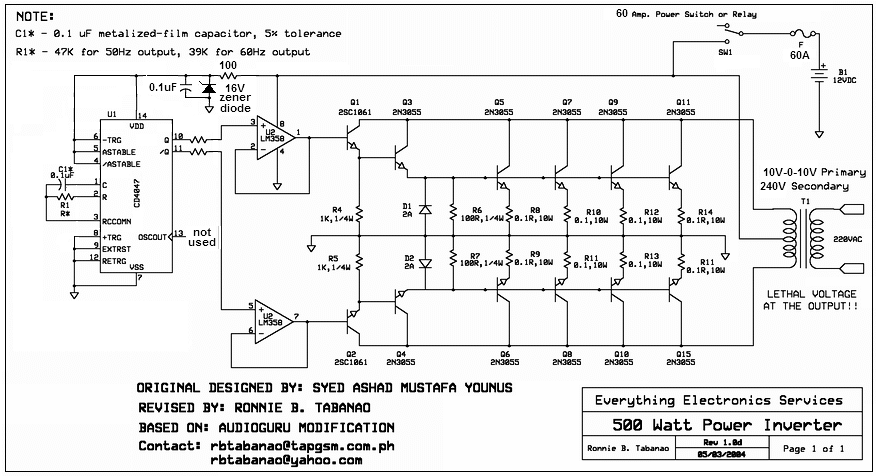 20097292438_500W inverter final.PNG
 PCB.PNG
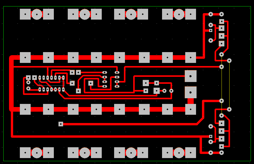
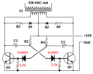 bad inverter corrected.PNG