| Orestes |
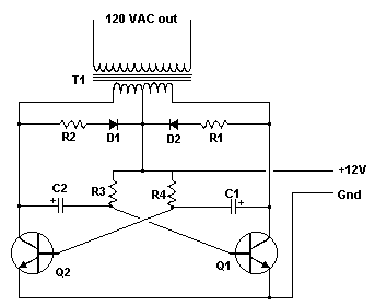
12VDC To 120VAC Inverter |
Wednesday, August 24, 2022 8:26:38 AM |
| 12 vu�lta es muy po�o es fatal, todo el que dijo que fun�iona es mentira |
| anonymous |
12VDC To 120VAC Inverter |
Thursday, May 19, 2022 3:23:07 PM |
| Its a good circuit for experimenting with but i would not
connect it to anything of value |
| Arthur |
12VDC To 120VAC Inverter |
Sunday, June 23, 2019 5:19:39 PM |
| I built it as shown, and the inverter worked so good. Electrolithic caps. Almost 60 hz. |
| Nadirsh |
12VDC To 120VAC Inverter |
Friday, January 13, 2017 2:44:51 PM |
| I want to make 230v from a12 v battery .so can u pleS give me a circute diagrom an explanation about it pleas |
| harry Mahalingam |
12VDC To 120VAC Inverter |
Tuesday, October 11, 2016 4:22:26 PM |
| Hi,
what is the transformer part if I wan to buy a brand new part. I check in may website but cannot find any part similar to this that will be helpful?
what should I change if I need increase current flow in the power inverter?
thanks
hari
|
| anonymous |
12VDC To 120VAC Inverter |
Saturday, August 01, 2015 10:24:12 PM |
| At what frequency does this circuit operate? Do you have any control of the frequency?
How do you control the six transistors required to convert dc to three phase ac? |
| anonymous |
12VDC To 120VAC Inverter |
Monday, January 05, 2015 3:23:53 AM |
| Not bad for a simple inverter--a least not if you don't mind a square-wave output, which is what you'll get out of this multivibrator-driven circuit. Not sure if I'd trust this to run any expensive electronics, though ... |
| mash |
12VDC To 120VAC Inverter |
Monday, August 25, 2014 5:38:27 PM |
| hi,what if i wanted to modify a transformer with 230v input,how many turns in secondary & primary windings also does this circuit produce pure sine wave & if not how to make it produce it,lastly the capacitor issue are tgey correct or something cause i've read tgat otgers have their"s exploding & i dont like such situations. |
| anonymous |
12VDC To 120VAC Inverter |
Wednesday, July 23, 2014 4:19:09 PM |
| The polarity of the capacitors is not fixed yet? |
| jimithy |
12VDC To 120VAC Inverter |
Saturday, August 11, 2012 5:10:02 AM |
| It took me a little while, but I got this circut so work on a SPICE program. Thanks for the schematic. It's badass! |