| Home > RX-7 > My RX-7 > Project Tina > Project Tina, September 20th, 2006: Gauges, Intercooler and Piping, Final Assembly and Startup |
| Home > RX-7 > My RX-7 > Project Tina > Project Tina, September 20th, 2006: Gauges, Intercooler and Piping, Final Assembly and Startup |
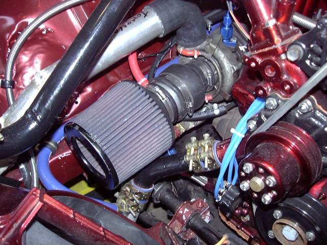
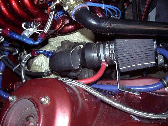
It only took a few minutes to make the turbo inlet duct. It's made of a 2.25" to 3" plumbing coupler and a small section of 3" aluminum tubing. The red vacuum hose connects to a nipple and leads over to the charcoal canister. That is the only part of the stock emissions system I retained because I can't stand oil catch cans and don't want the car to reek like fuel from an open vented fuel tank.
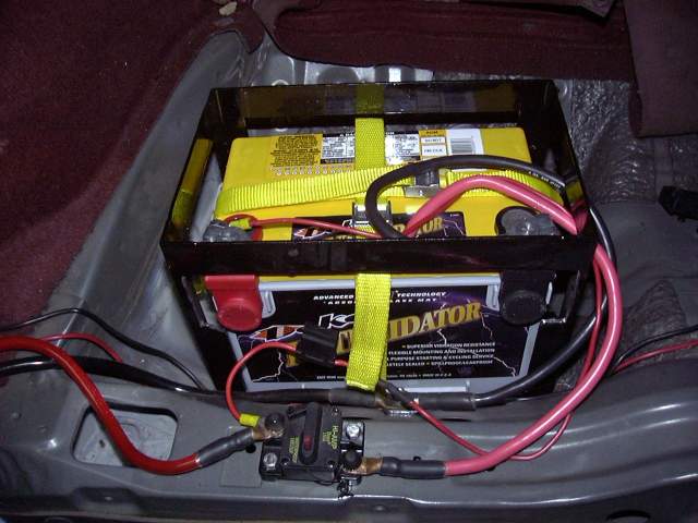
The battery I chose for the car is the Deka Intimidator. This battery is an 850 CCA 55AH AGM monster that has been well proven in electric vehicle racing. In fact tests have shown this battery capable of producing nearly 3000A into a direct short without any long term damage. It is a deep cycle battery in standard group 34 size, with both top and side terminals. Deka has abandoned the "spiral cell" technology because they can pack more lead (and thus more AHs) into a standard square formfactor. I chose to use the top terminals since they are capable of carrying more current then side terminals. My only annoyance is that the spec sheet that I originally referenced when I designed the battery tray did not account for the size of the side terminals so some adjustment of the box was necessary to make the battery fit. The yellow straps are something I picked up at the local tow truck store. They are designed to secure vehicles to flatbeds and are rated at 1200 LBs each. Just after installation I immediately charged the battery to 14.9V so it would stay nice and fresh.
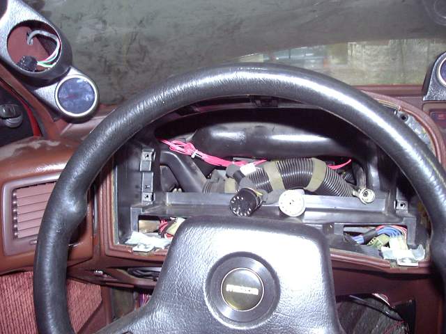
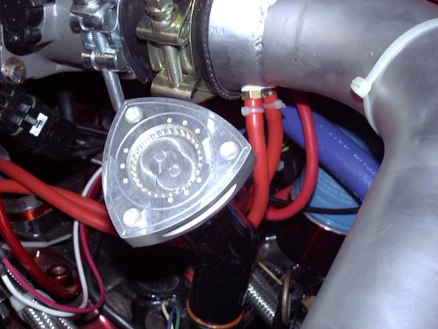
My Nexus boost gauge arrived so I needed to get it's GM style MAP sensor installed. Because I already had a vacuum line leading into the cabin for the Microtech's MAP sensor, I made a bracket to install the new MAP sensor in place of the factory atmospheric pressure sensor located in the passenger kick panel. The vacuum line from the engine bay then Ts to connect to the Microtech and Nexus MAP sensor. Note that these sensors must be mounted with the vacuum port facing downwards to prevent contamination from condensation. Interestingly, that bracket was made from a bit of scrap metal that I had laying around. In it's previous life it was the battery retaining bracket in an APC 800RT computer UPS.

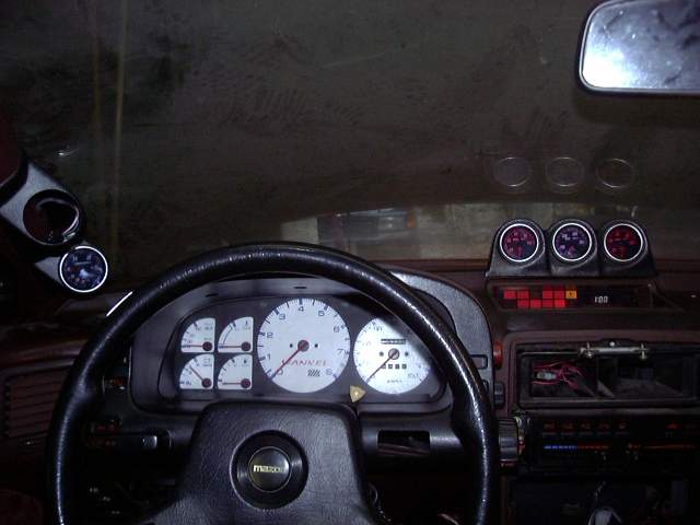
The boost gauge fit into the existing A-pillar pod. I ran the bus cable from the secondary Nexus gauges through the instrument cluster opening and up the pillar. I did have to extend the harness somewhat since the Nexus control box only comes with one long cable as they assume all your gauges will be mounted side by side. The empty opening in the pod is for the wideband which will be installed after the initial rough tune. Again, it is Nexus and will connect to the bus cable sitting in the pod. I'll add a single pod later on to house the Nexus water temp gauge and just continue the bus. These gauges are so easy and neat to wire that it is a joy hooking them up.
Now that I had the battery and all the electrical connected, I couldn't resist powering up the car. With a fire extinguisher handy I hit the main breaker and set the key to "RUN". The Nexus gauges powered up and the electrical system of the car sprang to life. Quick checks confirmed that all the stock systems (headlights, wipers, heater, etc.) worked fine, and the Microtech showed that all sensors were reading properly. I then went through the TPS calibration procedure (very easy with any standalone) and set the trigger temperature for the e-fan. A car with a new electrical system certainly is a pleasure! Even under full load the Intimidator refused to drop below 13.5V while cranking and none of the dash or headlights dimmed when other accessories were switched on. Exactly what I wanted.
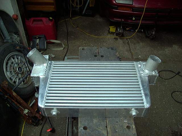
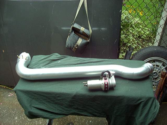
With the electrical side ready to go, it was time to finish welding the intercooler. I'd like to thank CP Racing for letting me have a few hours on their TIG welder continuously contaminating and having to regrind their tungstens. TIG welding aluminum is a challenge but after a few hours I was making some nice beads with solid penetration. Yeah, the modified end tanks look a little strange but that's just aesthetic.
The intercooler could then be mounted to the car.
Here's the top view of the intercooler showing the mounting brackets, ignition box and wiring, relays, etc. The hood latch still fits but at some point I will need to make a new center bracket.
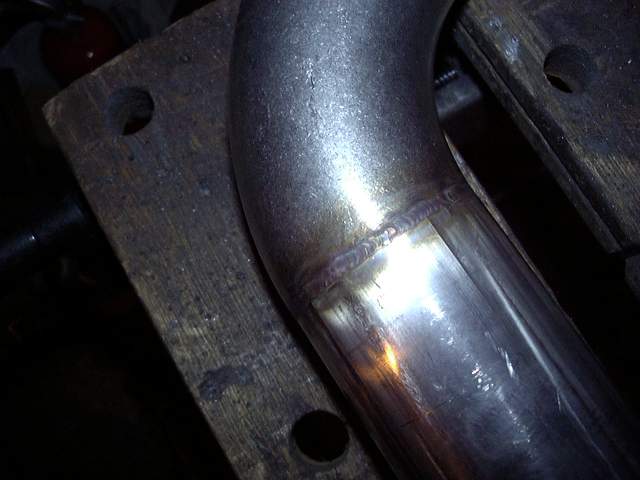
The drivers side intercooler pipe was finish welded at the same time I TIG'ed up the intercooler. I decided to TIG it since it meant that there would be no excess penetration and very little prep before it gets painted.
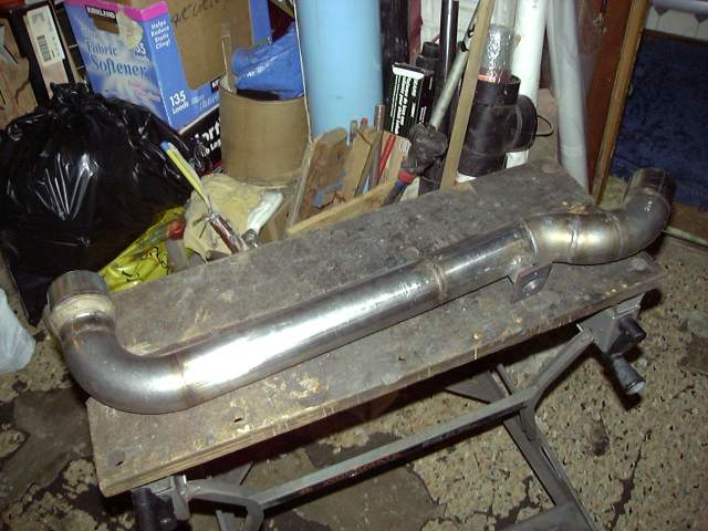
TIG is such a nice process with no splatter, very little smoke and often no need for filler. Because I had been very careful with my cuts on the pipe (knowing that I would be TIG welding it) I could just make a series of fusion welds. Shown below is what's typical of a TIG weld. Notice the tiny bead, absence of splatter and minimal heating to the surrounding area. I've got to get me one of those...
Three holes were then drilled in the thick 2.5" to 3" transition and then tapped for 1/8" NPT to provide air nipples for the three circuits mentioned previously. I then sanded the entire pipe down with an 80 grit flap wheel and painted with silver/aluminum paint. Once the paint was cured, the BOV and nipples were installed. Plenty of copper gasket goo was used on the BOV and Teflon sealing compound keeps the nipple's threads from leaking.
Before the intercooler piping was installed I made a small bracket to keep the TID from wiggling around, heat wrapped the turbo and manifold, then heat wrapped the downpipe. The heat wrap makes a HUGE difference in keeping heat out of the engine bay. With the engine running, you can actually lay your hand on top of the turbine housing for just under 5 seconds before it becomes uncomfortable. The heat wrapping job is far worse then the picture makes it appear since the irregular shape of the turbo and manifold make it difficult. When I upgrade the turbo I will ceramic coat and heat wrap the manifold, but use a blanket on the turbine housing.
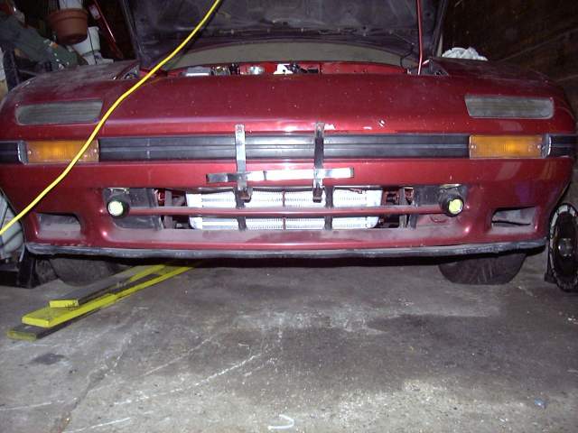
The intercooler pipes were then installed using silicone couplers and T-bolt clamps. Everything went in very easily even though access to some of the clamps is a bit restricted.
A closeup of the nifty rotor oil cap and air lines to the metering oil nozzles, primary injector air bleeds and purge valve. I zip-tie all my vacuum lines.
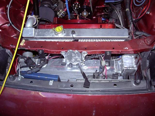
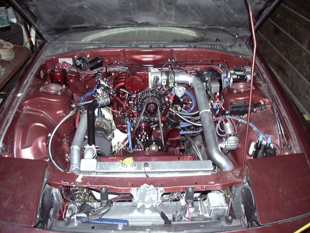
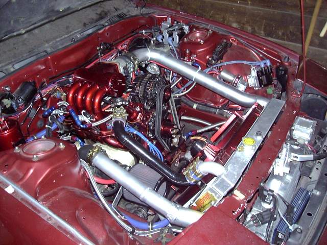
Drivers side view of the completed engine bay.
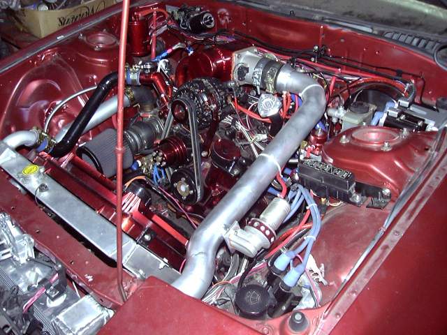
And from the passenger side.
So there you have it. At this point, the car was ready to start. All that remained was to put some gas in the tank, push it out of the garage and turn the key!
This last Saturday was the day when all the little things were looked after. Cables were tied back, hoses clamped down, interior given a quick cleaning, etc. A trip to the gas station on Friday and again on Saturday meant that on Sunday there was 45 liters of fuel in the tank. This is very important on a first start since there is nothing more frustrating then attempting to get a car going only to find out the tank is empty, or to run out halfway through.
Around 1PM on Sunday, Jeff came over as a witness and to provide another set of hands for the last minute tasks. Together we bolted in the seats and seatbelts and did a quick walk-around to make sure that everything was ready to go.
I connected the fuel pump and keyed the car to "RUN" to prime the system. As the Aeromotive pump came to life it groaned for a few seconds as it primed itself then settled down to a steady hum as fuel began to circulate through the system. After a few seconds, the Microtech shut off the pump prime and I got out of the car to check for leaks. None were apparent so it was now time to set the static fuel pressure. I panicked slightly for a moment since it did not seem that I had the appropriately sized Allen key to adjust the Aeromotive fuel pressure regulator but the needle nosed pliers did the job. Fuel pressure was set to 40 PSI, which incidentally is the minimum fuel pressure for the regulator.
Now it was show time so I started the camera, made my introductions and stepped into the car. Once again I primed the fuel system, then turned the key to "START". The engine began to rotate and did one revolution, then another, then another at which point the Microtech synced up to the CAS and started firing ignition and fuel. Another revolution and the engine sprang to life with a roar and cloud of smoke. First try, baby! The silence of the afternoon was cut by the "brap brap brap" as the engine cleared it's throat of assembly lube, vascelene, oil and metal shavings. A large cloud of smoke emanated from the exhaust and fogged the driveway.
I let the engine run a few seconds then gradually let off the throttle as though I somehow expected it to idle. It did not, and simply stalled. An attempt to restart it was rewarded with just a lot of cranking so after a minute or so I gave up, pulled a bunch of fuel out of the cranking map, then tried again. The engine started almost immediately and I held the throttle at 2000 RPM until it had warmed up to operating temperature. Once the engine was warmed, the heater was cranked up to fill the core and circulate coolant to bleed out any air bubbles. After a few minutes the engine was turned off and once again checked for leaks.
None were found so I set the idle speed to about 1500RPM, restarted the engine and pulled fuel from the idle map until it idled by itself.
I couldn't resist so after popping the champagne and sharing a toast with those around I fired up the car and we went for a drive. Since there were no plates nor insurance the drive basically amounted to a trip around the block but it did give me time to check that the transmission and drivetrain is sound. I must say that I am very impressed with how well the car drove, even untuned and with an engine having run a total of about 20 minutes. It took throttle easily, and the large throttle body was not as hard to control as I thought it would be. Compared to a stock RX-7 (and even those with a lightened flywheel) it revs quickly and freely. A little bit more throttle and the turbo wanted to spool up even as low as 2000 RPM. I'm very excited to see how the car responds under boost after it is broken in even with the stock turbo. It currently pulls about 14" of vacuum while idling and about 10" under light load so it should be easy to tune.
There are three minor problems though. There seems to be a slight oil leak from the oil cooler line at the rear iron which is probably just a loose fitting. One of the metering oil lines is also leaking, which is again just likely a loose crimp fitting. And finally there is a fuel leak at the filter input which I suspect is caused by a NPT fitting that was machined a little strange and thus would only go in a few threads. A new fitting is on the way and while I have the car in the air to replace it I'll also take care of the other leaks.
Of course, the whole process was captured on video as I promised last time. That video can be found below. It is about 35 MB and in Windows Media Format. I got lazy and just used Windows Movie Maker since at this point I assume that it's become close enough to a standard at this point. I'm also using the Coral Content Distribution Network to keep some of the load of my servers. The link below should work for almost everyone but if it doesn't, there is also a version on YouTube. You're going to want to right click and "Save As" as there is not enough bandwidth to support streaming.
Project Tina Phase II Startup Video (Windows Media Version)
Project Tina Phase II Startup Video (YouTube Version)
Keep in mind that these videos show an engine that doesn't even have an hour of runtime on it. The fuel maps are all still untuned and the timing isn't even set yet past what is required to start the car.
Today I pushed the car out of the garage to take a look at the fuel leak. I didn't want to run the car because it was leaking fuel and I didn't want the system pressurized. Once the car was in the air it looked like the problem was as I assumed, an NPT fitting that did not seal due to inadequate thread engagement. However as soon as I pressurized the system I found out that it was much worse.
The fittings didn't leak at all and the hoses were perfectly dry. However there was seepage at the Mallory filter where the two halves of the canister met. After wiping off the filter and repressurizing it was obvious that was the source of the leak. I pulled the filter apart and checked the big o-ring that seals it, covered it with Hylomar and then reinstalled the canister.
When I pressurized the system it leaked even more. Around the entire circumference of the filter canister fuel literally poured out of the seam.
At the moment I'm not sure what's the problem. Maybe the o-ring is bad, maybe the wrong o-ring is installed, maybe there is a machining error, etc. Who knows. However I am very frustrated at the whole thing because it means that I can't drive the car. I'm going to have to call Mallory and see about getting a replacement under warranty but even if they ship it immediately it still means the car will sit in the garage for another week. It's rapidly approaching October where snow can be expected later in the month. I'd be mighty pissed if I can't drive the car this year.
Overall I'm very unhappy with Mallory at this moment and I can't recommend that anyone else use their filter. Mine is probably just defective but then again none of my Aeromotive or Russel parts had problems. And the 160 Series Competition Filter was certainly NOT cheap.
My oil leak is likely the metering oil pump. Looks like there is a lot of oil leaking at the shaft but I will have to run the car more to find out which I can't do with a fuel leak...
The fuel leak is solved. Last week I waited until Wednesday to hear from Mallory, but did not receive an email from them. So I called and was basically told that they would warranty the filter but it could take 3 weeks...That was not going to work for me. I got the o-ring size from the Mallory guy over the phone and went hunting for one locally. After calling nearly every hydraulic shop in town I finally found someone who could order the 2.86" x 0.070" o-ring in Viton.
Friday morning, the o-rings arrived. A big thanks to Custom Fluid Power in London Ontario for being so quick with such a small order. I also ordered the o-rings required to rebuild the metering oil pump.
Sunday I was able to get some time to work on the car. So I pulled the filter, cleaned the mating surfaces, coated the o-ring and filter body in vascelene and then reinstalled the filter. Holding my breath I turned the key and was happy to see no leaks. After running the pump for a few minutes the filter was still leak free so I put the car back on the ground to see about doing some tuning on the cold start and setting the timing...
I still have oil leak issues though. The metering pump is dripping from the shaft so I will rebuild it soon. And it seems that I have the infamous front hub bolt leak. I have a feeling that when I installed and torqued the front eccentric bolt I coated the o-ring in Hylomar and not grease. Grease is necessary in these circumstances to prevent killing the o-ring while the bolt is being screwed into place. At some point I'll have to pull that bolt and replace the o-ring and crush washer.