I was wondering about this schematic. Just a mental exercise, you know. What caught my attention is the fact that both tantalum caps showed in - as I think - reversed polarity. Look at the schematics: the base of the transistor never gets more than 1V above emitter voltage - when the transistor is opened; when the transistor is closed, the base voltage may go well below 0. The other side of the cap is con
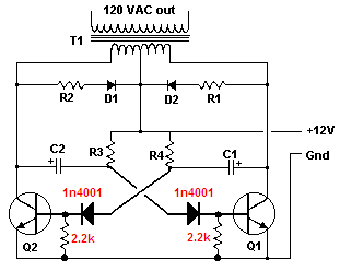
Are you talking about the extremely simple 12VDC to 120VAC inverter? Yes, its capacitors had backwards polarity but their polarity has been fixed.
The collector side of each capacitor goes positive and to 0V. The base side of each capacitor goes positive about 1V and goes negative enough to cause avalanche breakdown. The circuit works very poorly with low power.
Doors open and close, not transistors. Transistors turn on and turn off.
the transistor never gets more than 1V above emitter voltage - when the transistor is opened; when the transistor is closed, the base voltage may go well below
the transistor never gets more than 1V above emitter voltage - when the transistor is opened
Of course it does. The collector of each transistor swings to +24V when the transistor turns off.
quote:when the transistor is closed, the base voltage may go well below
Why do you talk about "open and closed" instead of turned on or turned off? Is it turned off when it is "open" and is it turned on when it is "closed"?
When the base voltage is +0.7V or a little higher then the transistor turns on. The transformer causes charged coupling capacitor to try to cause the base voltage of the other transistor to go negative to -23V but the emitter-base has avalanche breakdown at about -7V or -8V which damages the transistor and capacitor. The horrible circuit should have diodes added in series with the bases and pull-down resistors to fix that like this:
 bad inverter corrected.PNG