| Home > RX-7 > My RX-7 > Project Tina > Project Tina, January 11th, 2006: Upper Intake Manifold Fabrication, Coolant Pipe Fab |
| Home > RX-7 > My RX-7 > Project Tina > Project Tina, January 11th, 2006: Upper Intake Manifold Fabrication, Coolant Pipe Fab |
I can't think of a snappy introduction, so let's just get down to it. Here's the latest installment in my ongoing turbo-NA-bridgeport project (Project Tina). This thread is a little different then most in that it primarily deals with only one task.
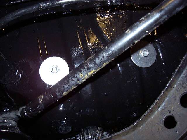
We last left off with the battery box being mounted into the passenger side storage bin. The bolts were secured on the underside of the car by using large flat washers to distribute the load. All fasteners are stainless, of course.
With the battery box out of the way, it was time to start a much more intricate fabrication project. The stock S4 NA intake, while being very functional in a near stock-port NA application, is not the best design for more radical configurations. Specifically, the tuning used relies on pressure waves generated by a rotor when it closes a secondary port. The runner length and width is tuned to allow this pressure wave to bounce back through the intake and force air into the opposite rotor through the open port. It works very well in a stock system, but what if you have ports that don't close such as a bridgeport? And have moved to forced induction? With a standalone? In this application simplicity and flow is more important then trying to use an intake designed for characteristics which the engine no longer possesses. Aside from that the NA intake is one very ugly piece of work, and all the emissions fittings and doodads for the stock ECU (not needed with a standalone) don't really help either.
So I had several options to "clean" it up. The TII intake is a little better but still suffers from stock ECU legacy clutter. The RE intake is a nice looking and unique piece but has the same issues as the TII intake. ITBs are great but require a new lower intake as well. For a while I had been wanting to make my own intake using a large aftermarket throttle body, plenum, straight runners and universal injector holders. Take a wild guess at what I decided to do.
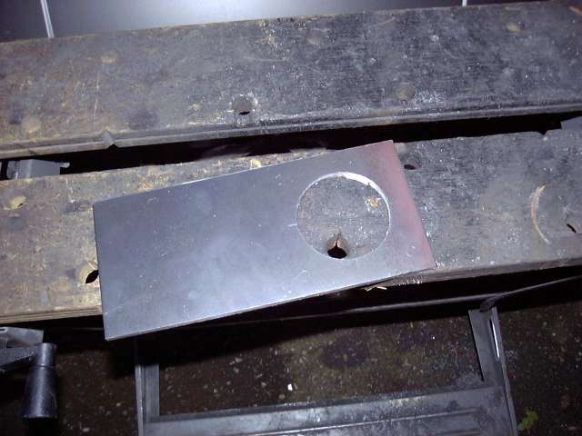
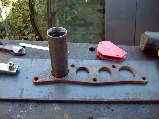
The first step starts innocently enough by fabricating a throttle body flange. 1/4" steel was used, and I began by boring a hole through it with a 3" hole saw. A sharp hole saw with the proper cutting oil and a powerful drill make this job very easy. It also helps to drill a pilot hole with a decent bit first so locate the pilot on the hole saw.
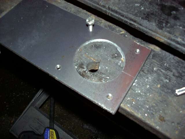
After drilling the main hole, I drilled and tapped the throttle body mounting holes. The idea was to do each step based on the probability of it screwing up. For example, drilling the big hole first so if it messes up I didn't have to redrill the 4 throttle body mounting holes. I also chose to drill the mounting holes after the big hole so that I could center the throttle body over the 3" hole first. Drilling and tapping is no big deal when you use a sharp drill bit, cutting oil, and a good set of taps. I never, ever use a tap dry unless it is in plastic, and always reverse the tap out every 1/2 turn to clear chips out of the flutes. The holes were tapped for M8x1.25, same as the stock throttle body nuts and bolts.
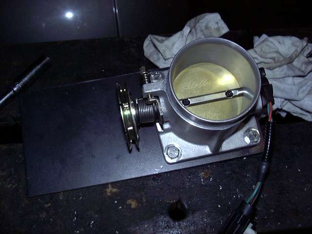
It was time to test mount the throttle body. That bad boy is an Edlebrock 75MM "Race" Mustang throttle body. What makes it "race" is that it excludes all the emissions stuff normally included in a Mustang throttle body (vacuum taps, EGR passage, etc.). It cost a little money, but the benefits are that it is band new with new seals and bearings, a full range TPS and a nifty Edlebrock sticker.
Now before anyone asks, you cannot install a throttle body like this on a stock intake. Well I guess you COULD with some fab work, but it would be a bad idea even if you are running a standalone. First it's not needed at all since the stock throttle body can flow to some crazy high horsepower numbers. Secondly, the stock ECU is NOT happy without the progressive throttle body that opens the primary ports before the secondary ports. Third, the TPS in incompatible.
Once the throttle body was fitted, I scribed a line around it so that the flange can be cut out. The flange was clamped into the work table and then each side was attacked with the angle grinder to get the rough dimensions, then the whole piece was finished off on the bench grinder.

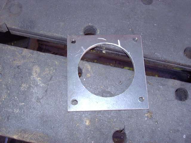
And here's the finished flange. A machinest's square was used to keep all the sides straight and the angles at perfect 90 degrees. The hole is offset slightly to one side because on the actual throttle body it is offset as well.
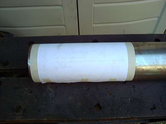
Once the throttle body flange was completed I had a general idea of how things would fit on the top of the engine. The next task then became to cut the plenum to size. It is constructed out of 4" steel tubing with a wall thickness of about 2MM. In order to cut tube straightly, the cut line must be even around the entire circumference of the tube. To achieve this a piece of paper was wrapped around the tube and the sides lined up. This formed two straight edges around the tube 8.5" apart. As luck would have it, I had already measured the plenum and determined that 8.5" was the length I wanted it. 8.5" is the approximate length of the manifold flange plus 1". It's the longest plenum that will fit without causing possible interference with the alternator and firewall. Ideally it could be a little longer to allow more area near the secondary runners to better encourage airflow.
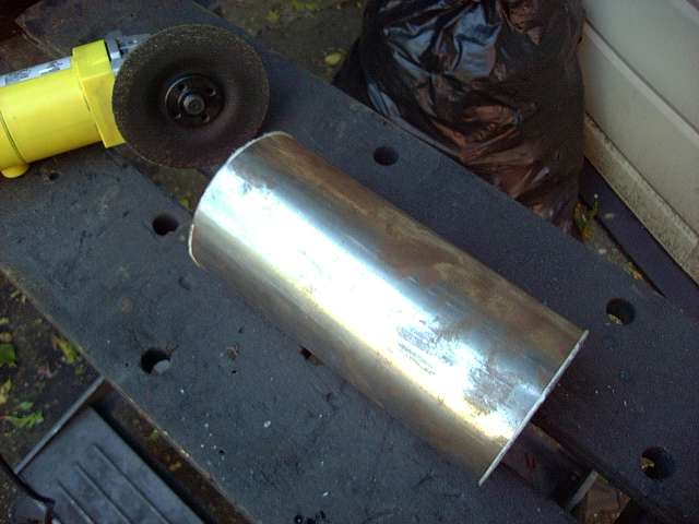
The tube was cut with a cutoff wheel on the angle grinder, then the edges were finished. I erred a little on the side of caution and cut about 1/8" long on each end just for good measure.
In order to attach the throttle body flange to the front of the plenum, two side pieces were needed. These have a flat area for the flange, and a curved area to match the plenum. They were rough cut out of a sheet of 3MM steel with the jigsaw and then the angle grinder was used to give them the curve. Each one was made individually so it would fit the plenum perfectly for easy welding.
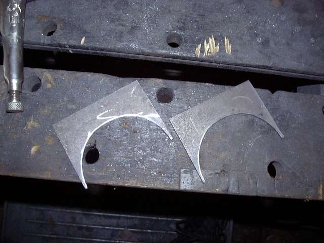
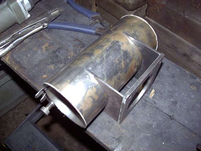
Here's a mockup of the throttle body area to give an idea of what it's supposed to look like. The top and bottom piece are just two squares of steel which fit between the two sides flush with the top of the flange. You'll see this later.
It's also interesting to note how quickly bare steel rusts in open air. When I picked up the tube originally it was shiny, but the oils and moisture from my hands had rusted it aggressively during only a few days exposure.
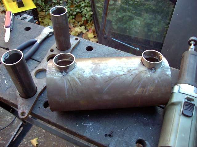
In order to attach the runners to the plenum some small adapter pieces were needed. Since end of the runner is flat it would not line up very well with the curved plenum, making it very annoying to line up and weld. The solution was to simply cut 4 birdsmouth pieces out of 1.5" tubing (same diameter as the runners). Each one was cut individually and test fitted multiple times during the process. After the birdsmouths were created, each one was cut to exactly 1.5 CM long. Having these pieces exactly the same would be critical for getting the first runners mounted straight.
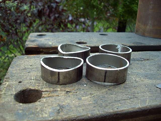
Test fitting the birdsmouths. There's still some work to be done on a few of them. I don't know why, but this picture always reminds me of bagpipes...
Now we're getting to the fun part. It was time to actually start to see what it would look like on the car. Based on research, I knew that I wanted the runners approximately 20 CM long. I was not about to put a great deal of effort into intake tuning (that is a HUGE amount of work) but I still wanted to keep the power band low enough to be useful. The 90 degree stainless weld els had an inner length of approximately 10 CM, so I needed 10CM runners.
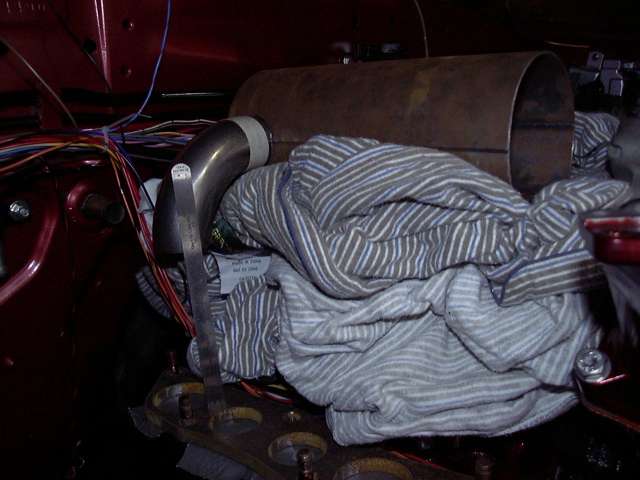
One of the bends was attached temporarily to a birdsmouth, and then the that assembly was glued to the plenum with a glue gun. From there I stacked cloths on top of the engine and positioned the plenum, using the cloths to vary the height of the plenum. After setting it up for 10CM distance between the 90 degree weld el and the flange, I test closed the hood several times and was relieved that everything fit. It was now time to cut the runners.
More measuring.
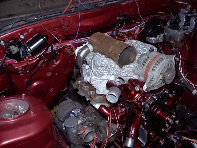
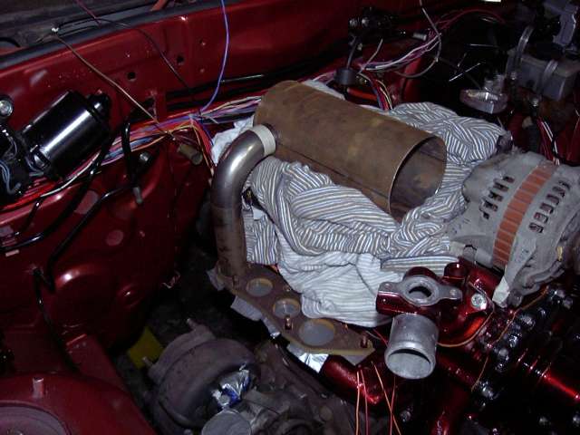
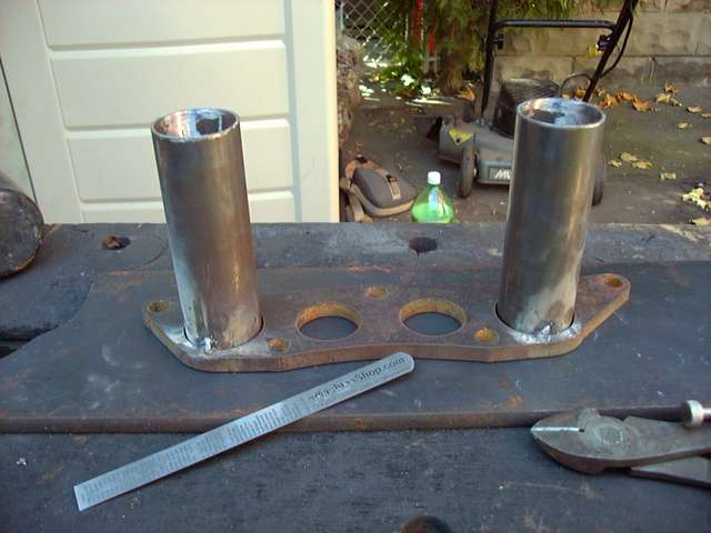
Two 1.5" diameter runners were cut to a length of 10.5CM. The extra 5MM was to give them play, and extend into the flange for blending purposes. With a runner in place, the hood was again test closed to make sure there were no interference problems. As well, it starts to give the impression of how the finished piece would look.
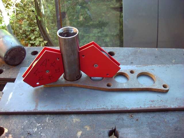
This is the point at which measuring becomes critical. The secondary runners must be perfectly straight since they are going to be used to locate the cutouts in the plenum, and thus locate the plenum itself. And since everything else comes off the plenum, it must be dead on. Welding magnets and a machinists square were used to check, check and check again the placement of the runner. It needed to be perfectly straight and extend 10.2CM from the top of the flange. The magnets were put into place and then the runners were adjusted by tapping with a hammer.
The first runner was tack welded into place, and then again checked for square. Welds always cause metal to move, so there was a certain amount of adjustment necessary to bring it back into line. This is something to pay serious attention to. Tacking must be done carefully and after each tack the assembly MUST be rechecked.
After the first runner was installed, the second followed. At this point things start to get weird, since the runners create an optical illusion and make it seem as if they are slanted. I found myself constantly rechecking only to discover that things were straight on all sides. This was a problem that would get worse as more curves were added to the assembly.
In order to locate the cutouts on the plenum, a birdsmouth was placed on top of each runner. The plenum was when placed into the birdsmouths and everything was lined up so there was equal space on each end of the plenum and the joints between the tubes were straight. Once everything lined up some minor clamping pressure kept things in place while the birdsmouth locations were traced onto the plenum with marker.
At that point each cutout was made by first using the cutoff wheel and then finishing with the die grinder. I should have just used a 1.5" hole saw as it would have taken a lot less time and truthfully, these cutouts did not need to be "perfect".
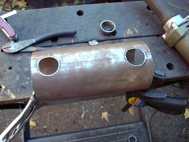
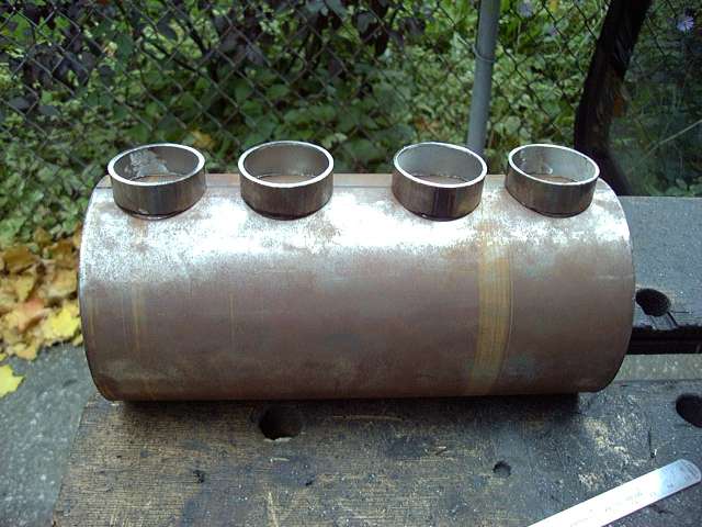
Once the holes were located the birdsmouths were tacked into place. Care had to be taken since when the tack cooled and shrunk, the birdsmouths had a tendency to "walk" in the direction of the tack. I had to anticipate how much the weld would shrink and then space the piece accordingly. The first one took several tries, but the 2nd one worked first try.
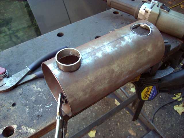
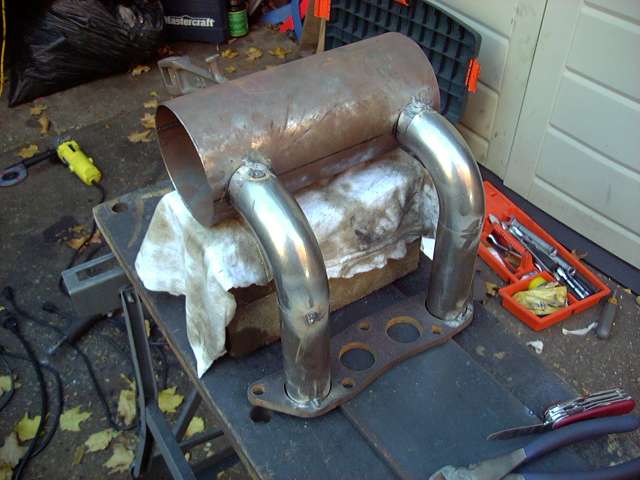
Finally the interesting stuff begins! The plenum was supported, and the lower flange and runner assembly placed below it. As it turns out, two bricks and a thin layer of cloth ended up being the exact height required. To locate the plenum, each 90 degree bend was placed such that one end was parallel to the mating surface of the birdsmouth, and the other end perfectly parallel to the top of the runner. Everything lined up without hassle the first try, and after all measurements were verified, both bends were tacked into place. Measurements were then checked again.