| Home > RX-7 > My RX-7 > Project Tina > Project Tina, January 11th, 2006: Upper Intake Manifold Fabrication, Coolant Pipe Fab |
| Home > RX-7 > My RX-7 > Project Tina > Project Tina, January 11th, 2006: Upper Intake Manifold Fabrication, Coolant Pipe Fab |
At this point it's starting to look like an intake. It was also obvious that the optical illusion of the multiple curves and parallel surfaces was starting to become pronounced. Every measurement I took told me that the intake was straight, but by eye it always looked warped. I think it was just a side effect of spending so much time staring at it since the feeling went away if I took a short break.
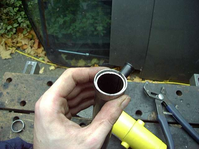
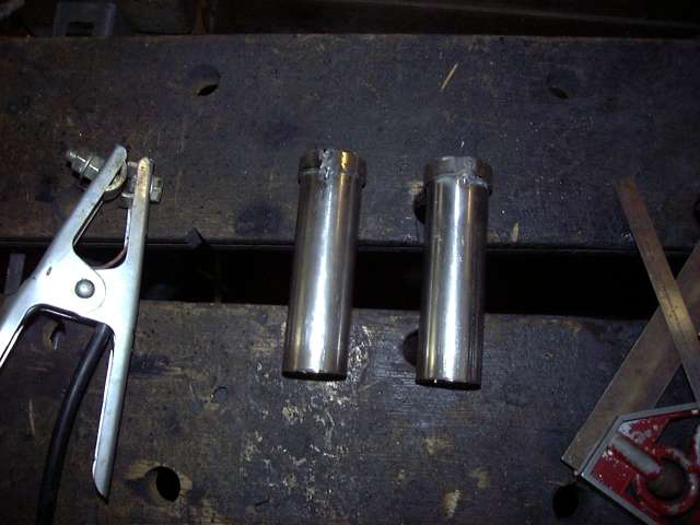
The secondary runners are 1.5", but the primary runners are 1.25". This is the closest standard measurement to stock so that the manifolds fit up properly. Also the primary runners don't need to flow as much as the secondaries due to their port size and duration as compared to the much larger secondaries. Anyway, since the 1.25" primary runners needed to meet up with 1.5" diameter weld els I had to construct two adapter rings to make things fit. The rings were made by cutting about 1CM of 1.5" tube and making a slit down the center. Careful crushing was then done with ViceGrips to shrink the diameter of the ring over the 1.25" primary runners.
A few quick tacks and the adapter rings are installed. The primary runners were cut to the same length as the secondary runners. Because of the adapter rings they ended up being a little long so they just penetrated farther into the flange.
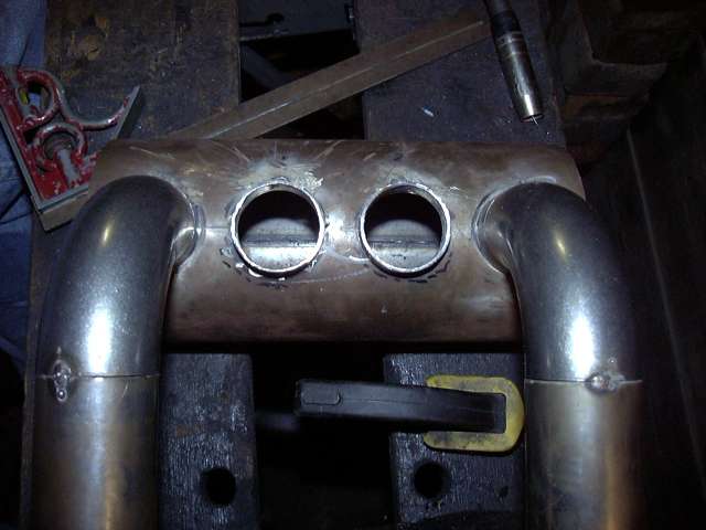
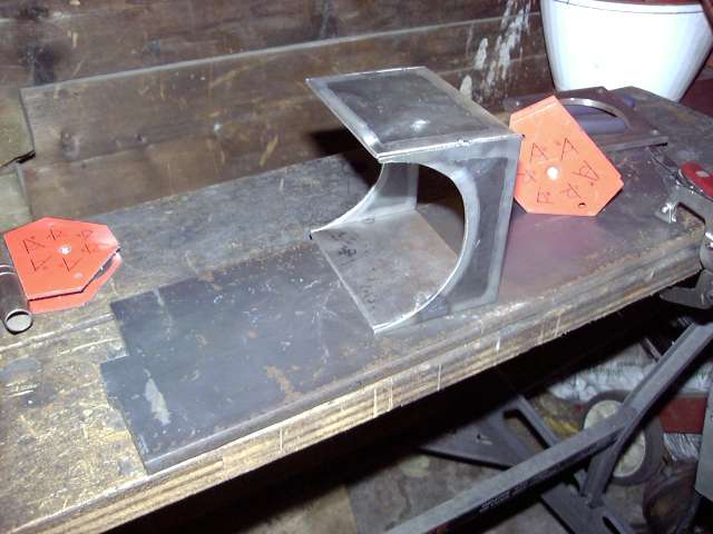
Again a birdsmouth was taped onto a 90 degree weld el and everything was set into place to get the position needed for the primary runner holes. Most of this was done by eyeball with only minimal measuring since the holes did not have to be perfect. Once all the finish welding was done, the inside of the weld are had to be ground smooth anyway so exact perfect hole placement isn't really needed for the primaries. The secondaries had to be perfect as the rest of the intake's dimensions relied on their placement.
The holes were then cut...
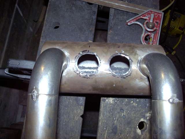
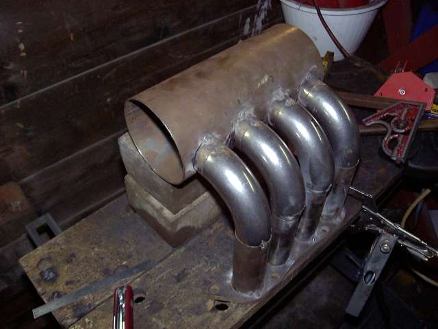
...and the birdsmouths tacked. This was an annoying process since the birdsmouths needed to be perfectly even across the entire intake. Even though they walked a little when the tack welds cooled, I was able to get them straight with a little trial and error.
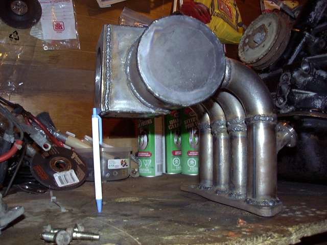
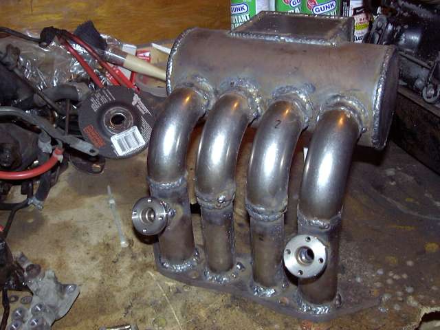
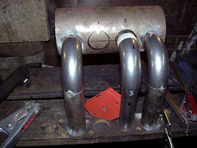
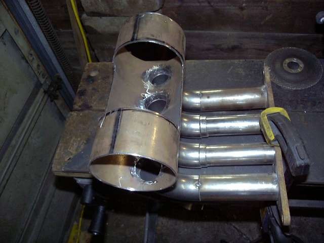
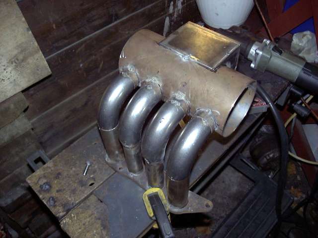
Installing the primary runners was again much more complicated then the secondaries since there was only one parallel surface to line up. The 90 degree bend went against the birdsmouth perfectly but the lower connection to the adapter ring was not as solid. The adapters fit slightly inside the 90 degree bend and centered since I had ground their tops into a taper. It was still a process of trial and error and the rightmost runner took several attempts to get right. You can also see the pronounced optical illusion in this picture caused by the intersecting lines. The plenum appears tilted towards the left based on the position of the camera, horizontal lines on the garage wall behind, and the gap between the plenum and the bricks. Measurement after measurement showed it to be less then 1MM off...I had previously chosen 1MM as my tolerance since that's about when the eye can notice something wrong. I was trying to choose my camera angles carefully to avoid this but I guess this one didn't quite work out.
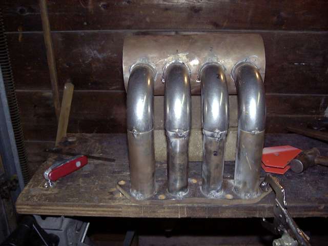
With a little wiggling, some minor cursing and a few tries, the runners lined up and were tacked in place. At this point, I also placed a tack on the inside area of the secondary runners to tighten up the structure.
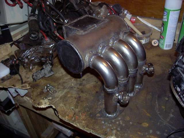
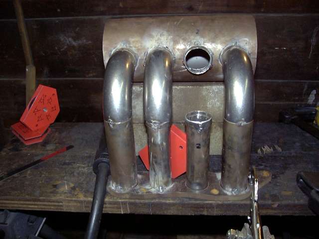
Now it's really starting to look like an intake!
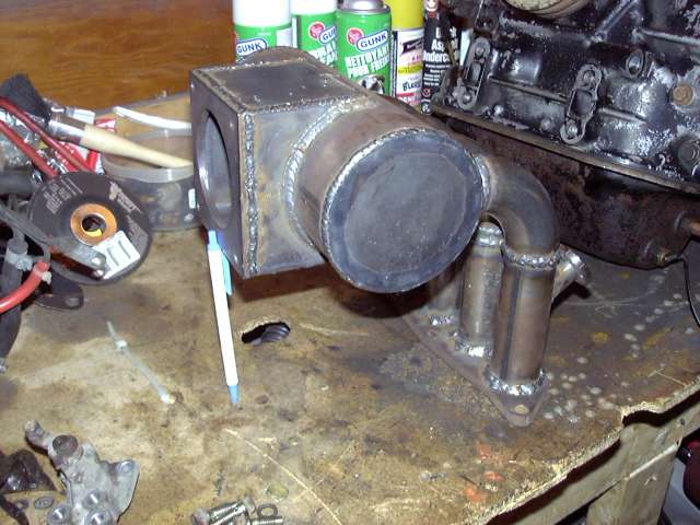
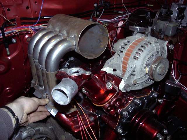
A this point I decided that I could not wait any longer for a test fit. I was quite relieved to find that yes, it still does in fact fit under the hood.
Each side of the throttle body mount was assembled separately. Magnets were used to assure perfect 90 degree angles. Again after tacking each piece needed to be straightened due to the shrinkage in the weld. A machinist square is the most important tool at this stage to keep all measurements in line. It's all in the details.
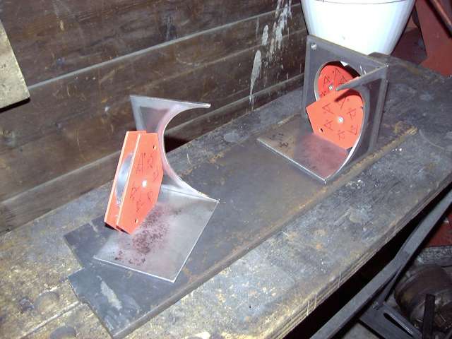
The mount halves were then assembled together using a series of inside tacks. The inside tacks brought the two halves into compression and thus prevented any warping. Final welding will take place on the outside seams.
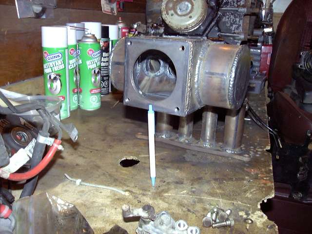
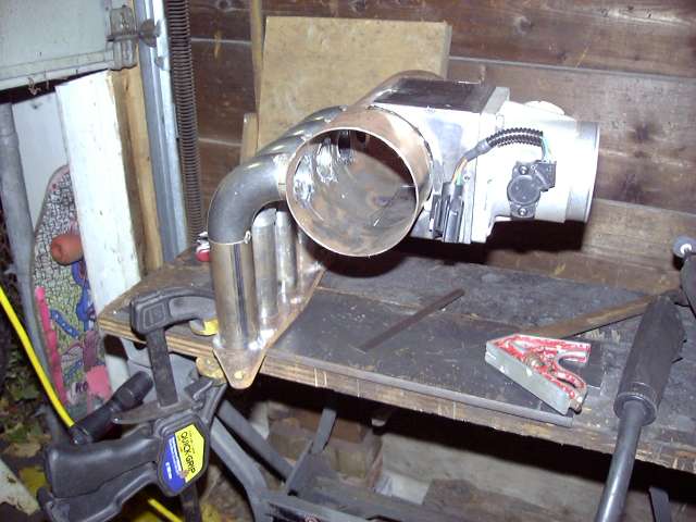
To mark the plenum the intake was clamped via the flange to the flat table. The throttle mount was then centered and leveled by using the machinists square to assure the flange was exactly perpendicular to the table. At that point the lines were drawn. It is not vitally important that this hole be exactly perfect since there will be grinding needed later to blend the surfaces internally.
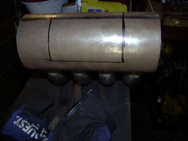
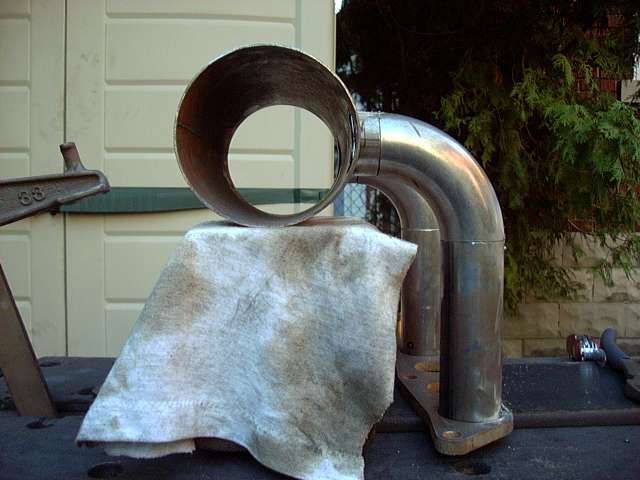
The cutout was made with a cutoff wheel and then the edges were finished with a die grinder. I was kind of worried that the huge hole I cut would cause the tube to deform and was relieved when it didn't.
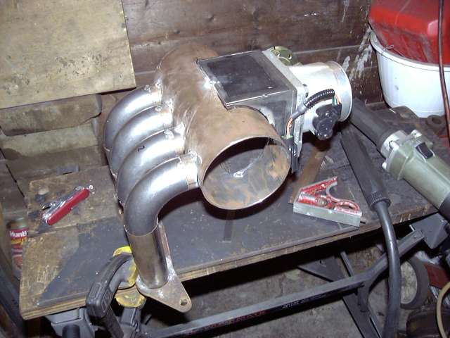
Once positioned, the mount was tacked into place at the top and bottom. This took a few tries because at the tacks cooled and shrunk the mount wanted to walk in the direction of the tack.
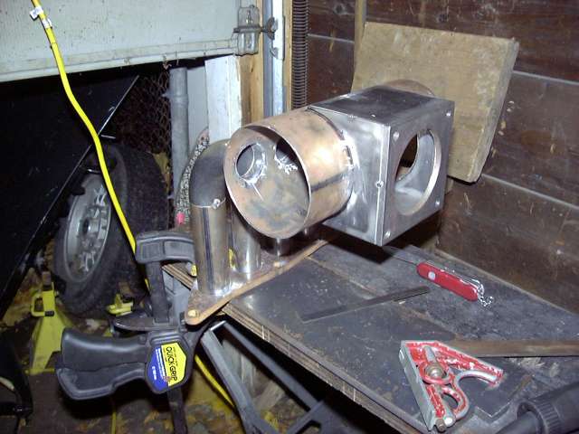
Finally I was able to test fit the throttle body. It bolted up and sat basically level so I was happy. What was even nicer is that it still fit on the car although it became obvious that the oil fill tube was totally in the way. The solution is covered later.
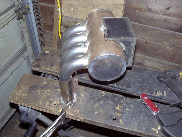
The plenum still needed to be sealed off, so two end caps were made. I don't think they turned out half bad considering I cut them out free-hand with the angle grinder after tracing the pattern using a spare section of 4" tube. The front cap was made of the same thickness steel as the rest of the intake tubing (about 1.5MM) while the rear end cap was made of thicker 3MM steel. This is to allow enough material so that the rear cap can be drilled and tapped for the intake air temp sensor and the necessary vacuum nipples.

The end caps were then tacked into place. They didn't have to be perfect since the edges would be welded and any excess material would be "absorbed" into the weld.
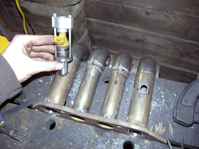
Of course on the NA, the stock upper intake manifold holds the secondary injectors so mine had to as well since I am still using the NA lower intake. I purchased some injector holders from ATP Turbo for this purpose. They make both a steel and aluminum version depending on what you intend to attach them to and each comes with a 1/4" NPT thread at the top for attachment to a fuel source. I bought steel of course. I must say I was very impressed with the quality. Installation was as simple as positioning the holder where I wanted it and marking then cutting out the appropriate sized hole. To cut the hole I initially drilled them out to about 3/8" and then used a carbide cutter on the Dremel to finish them off. The yellow injector you see in the picture is NOT the injector I will be using in the car. It's just an old Ford 220CC injector I had laying around. When the intake is bolted onto the car, I will be installing Ford 1600CC injectors which fit perfectly without modification into the ATP holders (they are designed to be as universal as possible).
It was now time to finish-weld the intake. The original plan was to use a TIG process for neat, tiny welds but that went out the window as soon as it was realized how little space there was between the runners to fit the TIG torch. Due to this limitation it was MIG'ed together. It meant more cleanup, but also made it possible to get into the tight areas that TIG could not reach. Thanks to CP Racing for doing the welding since if I had used flux-core I probably would have had to put an additional 5 hours into cleaning it up (flux core is many things, but pretty welding process it is not). Chris welded up the intake while I was busy wiring a Megasquirt on a MKII Supra. To follow are several pictures of the totally welded intake.