| anonymous |
Ringing Phone Light Flasher |
Wednesday, November 21, 2018 8:47:57 AM |
| The 2 zenners D2, d2 are wrong connected, they should be indeed series but anode to anode connected, as here http://www.epanorama.net/circuits/telephone_ringer.html |
| John |
Ringing Phone Light Flasher |
Tuesday, February 27, 2018 7:56:40 PM |
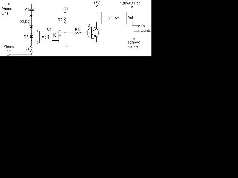
| If you want the light to follow the ring cadence instead of flickering, place a filter capacitor between pins 4 and 5 of U1 to filter the 20 Hertz pulsed signal.
To increase the voltage used for the relay, adjust R2 and R3 to ensure the current flowing is not too high for U1 and Q1.
If using a mechanical relay, place a snubber diode across the coil of the relay. |
| anonymous |
Ringing Phone Light Flasher |
Saturday, June 27, 2015 12:19:18 PM |
| I have modified the circuit to work in my situation. A pair of 110 volt regular light bulbs come on each time the phone rings. The ring voltage was too low to work with this circuit after I installed MagicJack so I needed to make a more sensitive circuit. Also, the circuit here is an always-on diagram. I need one that comes on only when the phone rings.You may write to me and I will send you the diagram. I also have a couple of good-working circuits that I designed. |
| MeIsHere |
Ringing Phone Light Flasher |
Thursday, January 31, 2013 8:52:50 PM |
| Thank you for the circuit , I was tested this circuit , and it works good .
68 |
| TONY |
Ringing Phone Light Flasher |
Tuesday, November 13, 2012 4:45:46 PM |
| Can you substitute the +5V dc with +12V dc for the relay side of the circuit, as I cannot find solid-state relays that works with less than 12V dc. |
| AbiG |
Ringing Phone Light Flasher |
Sunday, July 29, 2012 6:13:27 AM |
| Thank you for defining this circuit; I was able to make it work...but I notice that the Relay chatters or turns On/Off while Ringing.
Normally, Telephone Ring is not continuous � it produces ringing tone once in 2 seconds�then the Relay also turns On/Off proportionately.
I believe adding a Capacitor to delay the turn OFF won�t work in this circuit as it works in Negative going pulse.
Is it possible to replace the circuit with PNP transistor? OR
Is there any standard way to turn the Relay ON continuous ?
|
| AbiG |
Ringing Phone Light Flasher |
Saturday, June 02, 2012 11:21:12 AM |
| Telephone Ringing. Telephone Ring is not continuous � it produces ringing tone once in 2 seconds�then the Relay also turns On/Off proportionately.
I believe adding a Capacitor to delay the turn OFF won�t work in this circuit as it works in Negative going pulse.
Is it possible to replace the circuit with PNP transistor? OR
Is there any standard way to turn the Relay ON continuous ?
|
| Phil |
Ringing Phone Light Flasher |
Sunday, May 06, 2012 12:45:14 PM |
| Well it does work butit works wrong the transistor is a npn so the relay is on until the phone rings., great if you are using a double pole relay not so great if your not . And yes the triac trik will work but why not use a solid state relay which has an inbuilt opti in it anyway so its just a cap one diode 1 resistor and the solid state relay |
| Michael |
Ringing Phone Light Flasher |
Wednesday, January 18, 2012 9:14:26 AM |
| Working on an offshore platform, I put this circuit in our emergency-phone, using 2 LED�s instead of D3 & U1 (Otherwise i used the spcified components), so the operators easily can identify when someone is calling on that line..Thanks :-) |
| John Stancliff |
Ringing Phone Light Flasher |
Monday, January 09, 2012 9:36:16 PM |
| Schematic show a external voltage of 5 Volts.... no reference given in notes concerning this..... why? (Editor's notes: It is assumed the reader will make up a 5V supply. Or just use 3 1.5V batteries in series.) |