| anonymous android |
Guitar Fuzz Effect |
Thursday, March 04, 2021 3:11:54 AM |
| Oops I meant 10-100pF between pin 2 and pin 6 |
| anonymous android |
Guitar Fuzz Effect |
Thursday, March 04, 2021 3:09:21 AM |
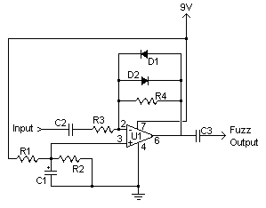
| This circuit is not a good choice for passive pickup guitars. Inverting op-amp circuits are at virtual ground at their inverting input. Since the input resistor is 1k�[ this will rob any pick up of its voice or resonance. A typical guitar pre-amp normally has between 500k�[-1M�[ input impedance. 1K�[ is 2 to 3 orders of magnitude to small, and making R3 larger will reduce the distortion gain and add thermal noise.
It would be better to switch this circuit to be an non-inverting input. That means connect the input side of R3 to the middle point between R1 and R2 voltage divider, and connect the input (through the coupling capacitor) to the non-inverting input. The Recommend LM741 has an non-inverting input impedance that is between 300k�[-2M�[.
Also I really don't like that this design completely omitted the filter capacitor across R1 and only put it across R2, it isn't critical you add it, but the filter caps should be symmetrical across the voltage divider so R2 and R1 both have the same value capacitor bypassing them.
RockAndTubes idea of adding a 1-2.2nF cap from pin 6 to ground won't make a noticeable difference. The output impedance of the opamp is very low 25-50�[ That would give a 1st order low pass up around a 1MHz. Better to put a between 10-100nF between pin 2 and pin 6. That will give a proper low pass filter.
|
| kurmitsa |
Guitar Fuzz Effect - diode replacement |
Friday, April 03, 2015 4:00:04 AM |
| This is a great circuit - thanks for sharing. Replaced the diodes with 1N4001 silicones and tried it out with a Telecaster-Bogner -setup. Now we're at the roots of rock. Thank you. |
| rockandtubes |
Guitar Fuzz Effect |
Saturday, January 12, 2013 6:42:37 AM |
| The frequency range is basically controled by the signal capacitors C2 and C3. If a trebley sound is wanted their capacitance should be reduced, p.e. 10nF to 20 nF on both positions will make an electric guitar better suited to solo work. The Treble Boosters use even lower values for C2, like 6.8 - 3.3 - 2.2 nF. For bass guitars I�ll probably add a small value capacitor (1 - 2.2 nF) between pin 6 of the opamp to ground or between pin 2 to ground. Another way to make the effect bassier is adding a small value capacitor on the negative feedback loop, i.e. on parallel with R4. |
| anonymous |
To control the amount of fuzz effect |
Sunday, June 10, 2012 11:50:07 PM |
| Replace R4 FOR 1M POT and you will be able to control the amount fuzz effect! |
| elmo |
Guitar Fuzz Effect |
Thursday, April 05, 2012 9:17:35 AM |
| it sounds too smaller and quiter ?
shall i take a OP circuit? |
| Yoruk |
Guitar Fuzz Effect |
Saturday, December 18, 2010 7:49:04 AM |
| Hello,
I build the circuit but it doesn't work... Everything looks good (tensions, ...) but I don't have sound. Is someone can help me ? Thanks |
| anonymous |
Guitar Fuzz Effect |
Monday, November 08, 2010 5:21:37 PM |
| I was able to build the Fuzz Effect circuit by connecting the output (pin 6) to the input (pin 2) of an LM386. I built a basic LM386 circuit (as noted on the datasheet), nothing fancy. I didn't have the correct values for Aaron's circuit (specifically diodes), but the sound is fair. I plan to build in a box. An all in one fuzzy guitar amp. |
| anonymous |
Guitar Fuzz Effect |
Monday, November 08, 2010 1:18:25 PM |
| Any chance I could use a 1N4742A zener instead? Thanks! |
| Annoying David |
Guitar Fuzz Effect |
Wednesday, October 28, 2009 11:46:39 AM |
| I'm fresh whit op-amps why does 9v go straight to ground by passing R1,R2 resistors? |