| Author |
 Topic Topic  |
|
audioguru
Nobel Prize Winner

Canada
4218 Posts |
 Posted - Feb 07 2008 : 10:55:17 AM Posted - Feb 07 2008 : 10:55:17 AM


|
quote:
Originally posted by Tolexp
Good day sir,i got your inverter circuit diagram of 12v to 120v. i try to practicalise it, but am unable to get 68uf,25v tantalum capacitor in my environment.please sir help with a substitution for the 68uf,25v tantalum capacitor or any capacitor to reply, because i can't get it in my environment. thanks sir
This inverter project does not work. Read about it in this thread. |
 |
|
|
aydot96
New Member
Nigeria
2 Posts |
Posted - Feb 09 2008 : 12:12:57 PM
|
| goodday sir,can you please send me another circuit of dc to ac inverter. i have the problem of getting 68uf,25v capacitor in my area.please what is the substitute the it. thanks |
aydot |
|
|
|
audioguru
Nobel Prize Winner
Canada
4218 Posts |
Posted - Feb 09 2008 : 1:13:52 PM
|
quote:
Originally posted by aydot96
goodday sir,can you please send me another circuit of dc to ac inverter. i have the problem of getting 68uf,25v capacitor in my area.please what is the substitute the it. thanks
If you search for inverter Circuit in Google then you will find links to hundreds of them. Some work and some don't. |
|
|
|
kasamiko
Apprentece

Philippines
6 Posts |
Posted - Feb 24 2008 : 04:44:44 AM


|
@audioguru...
I'm suffering from INVERTER paranoia....
rhonn |
rHoNnZ |
|
|
|
tim
Mad Scientist

198 Posts |
Posted - Feb 24 2008 : 06:17:15 AM
|
| yup hes right that the inverter here dont work . ive tried EVERYTHING to get it to work. LOL LOL. |
|
|
|
audioguru
Nobel Prize Winner
Canada
4218 Posts |
Posted - Feb 24 2008 : 11:18:31 AM
|
| Rhonn's 500W inverter works perfectly and has for years. |
|
|
|
kasamiko
Apprentece
Philippines
6 Posts |
Posted - Feb 24 2008 : 8:33:42 PM
|
quote:
Originally posted by audioguru
Rhonn's 500W inverter works perfectly and has for years.
In fact i've already produced dozen of it..powering 14" colored tv's and cheap China made dvd's...
the only problem I've encountered is when the inverter is working with loads and suddenly the alligator clips slip off the battery terminal...all output transistors are toasted.. |
rHoNnZ |
|
|
|
audioguru
Nobel Prize Winner
Canada
4218 Posts |
Posted - Feb 24 2008 : 9:56:05 PM
|
Hi Rhonn,
Powerful Zener diodes across the ouput transistors will arrest the high voltage spike and save the transistors. Maybe about 40V/10W.
|
|
|
|
kasamiko
Apprentece
Philippines
6 Posts |
Posted - Feb 25 2008 : 01:21:07 AM
|
I think i should be shifting to MOSFET now..
I'll start with IRFZ44...
cooler..more efficient.. |
rHoNnZ |
|
|
|
WilliamW1979
New Member
USA
2 Posts |
Posted - Mar 09 2008 : 8:23:01 PM

|
| Was is he math formula to compute how many Watts can be handled based on the changing of the components of T1, Q1, and Q2? This is obviously for a 300 Watt system so lets say I want to create a 5,000 Watt system, how would I go about doing that? |
|
|
|
audioguru
Nobel Prize Winner
Canada
4218 Posts |
Posted - Mar 09 2008 : 11:58:02 PM
|
Changing T1, Q1 and Q2 in this simple circuit has nothing to do with increasing its output power because the circuit doesn't work. Its output power is only about 25W with a low output voltage, not anywhere near 300W.
The polarity of the capacitors are backwards and the transistors have avalanche breakdown. The transistors don't have enough base current.
You want the math? It is difficult to determine how much power is wasted by heating the backwards capacitors with the very high current pulses caused by the transistors avalanching.
The transistors have base resistors that are 180 ohms so the base current is only (13.2V - 1.0V)/180= 68mA. The typical current gain is 50 so the collector current is 3.4A. The output power is 13.2V x 3.4A= 44.9W minus the wasted power. The transistors saturate poorly unless the base current is much higher. If your transistors have minimum gain then the output power and voltage will be much lower.
For an output power of 300W then the power from the battery must be about 360W. Then the current in each transistor must be 360W/13.2V= 27.3A. But the absolute max allowed current for the 2N3055 transistors is 15A and they work poorly at 10A to 15A. I don't know of a power transistor that has a good current gain with a current of 27.3A.
Kasamiko's inverter is 500W and uses 8 2N3055 output transistors, 2 2N3055 driver transistors plus pre-driver transistors. It has a separate oscillator so its transistors do not have avalanche breakdown and its capacitors use low power.
5000W is rediculous from a 12V battery. The current would be 500A! |
|
|
|
mrservn
New Member
1 Posts |
Posted - Apr 23 2008 : 03:47:43 AM
|
Dear Mr Audioguru.
The Chinese, Indian, Vietnamese,... will very thank you, if you were designed a inverter 12VDC to 220V Ac sine ware, with more effect than this http://www.aaroncake.net/forum/topic.asp?TOPIC_ID=2996&whichpage=24. Because it very heavy, expensive (the transformer) .
Did you know they living in very hot environment (34oC to 39oC)but electric company cut electric two or three times a week (6AM to 22PA). So that a 350W to 500W inverter is very important for a small family, to Fans, TV, lights,..
PS. I am sorry about my English skill. |
Edited by - mrservn on Apr 23 2008 03:50:08 AM |
|
|
|
audioguru
Nobel Prize Winner
Canada
4218 Posts |
Posted - Apr 23 2008 : 12:03:42 PM
|
I don't know why 3rd world countries are full of poverty, have no education and have unreliable electricity.
I can buy a modern inverter that is made in a 3rd world country much cheaper than I can make one. But I don't need one because my electricity is reliable and is cheap.
Why can't people over there buy a cheap inverter that is made over there?
I didn't design the very old inverter circuit that uses a heavy expensive transformer. I just fixed the circuit so it could be used in The Philippines where many people have no electricity. 2N3055 transistors are available there but not Mosfets. |
|
|
|
kivdenn
Nobel Prize Winner
Uganda
535 Posts |
Posted - Apr 24 2008 : 07:26:47 AM
|
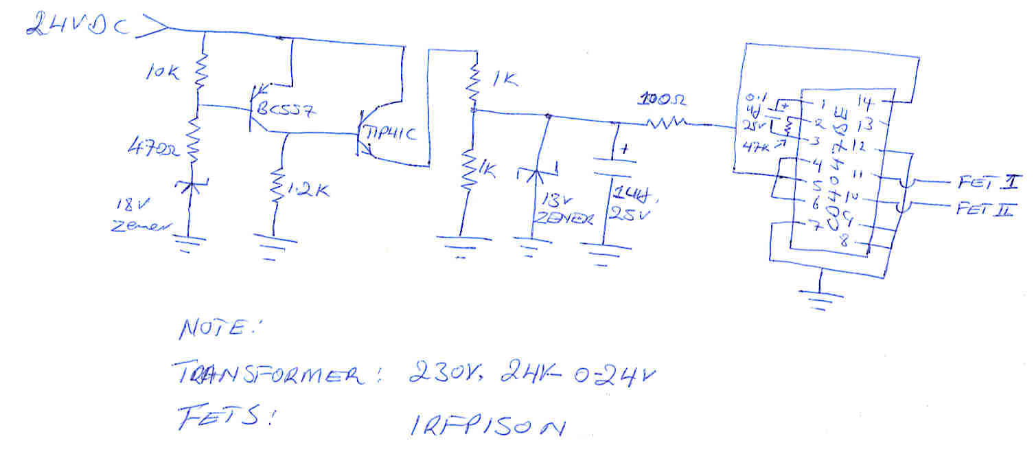
Audioguru why dont you give them this circuit, you helped build it and I have used it to make 15 DC-AC inverters and now they are working very well with no side effects. The problem is that its abit hard to get the 0.1uf electrolite capacitor but the rest of the parts are readily available on any market.
Just feed the 12VDC into the centre tap of a 12-0-12 5Amp transformer and connect each of the other two transformer wires to the drain of a mosfet transistor and connect their sources to the ground. The gates of the two mosfet transistors should be connected to pin 10 and 11 of the oscilator respectively.(Do this after ensuring that the oscilator realy produces oscilations r you will fry the fets). You should now be having a DC to AC inverter with a low current power on switch and a simple but practical low battery disconnect option that shuts down at 10VDC. The circuit shown was desined to run on 24V but iot can very well be adopted for the 12 configurations. Just change the 18v Zenner to 10V and omit the two 10K and the 100 Ohm resistors and connect the emiter of the TIP31C to a 100 Ohm resitor and then connect it to 13V zener in paralel with a 1uf,25 capacitor and then to pin 14 of the cd4047
Download Attachment:  OSCil.jpg OSCil.jpg
55.59�KB
 |
Edited by - kivdenn on Apr 24 2008 07:38:21 AM |
|
|
|
audioguru
Nobel Prize Winner
Canada
4218 Posts |
Posted - Apr 24 2008 : 10:22:59 AM
|
The 0.1uF capacitor in the oscillator must not be an electrolytic type. Electrolytic capacitors are polarized for DC but in the CD4047 it has AC. An electrolytic capacitor has a horrible tolerance of -20% to +50%.
Use a metalized plastic film type of capacitor with a tight tolerance of 5%.
Why do you use a TIP41C power transistor in the circuit that has very low power. An ordinary little transistor will be fine. |
|
|
|
Topic |
|