Aaron's Homepage Forum
Home | Profile | Register | Active Topics | Members | Search | FAQ
Username:
Password:
Save Password
Forgot your Password?

 All Forums
 Electronics
 Power Supply
 12/120V inverter again
 New Topic  Reply to Topic
 Printer Friendly
Previous Page | Next Page
Author Previous Topic Topic Next Topic
Page: of 63

audioguru
Nobel Prize Winner

Canada
4218 Posts

Posted - Apr 30 2008 :  10:23:52 AM  Show Profile  Reply with Quote
The "snubber" is a capacitor in series with a resistor and is connected at the output of the inverter to reduce voltage spikes. The capacitor must have a voltage rating that is higher than the peak output voltage.

Two back-to-back zener diodes in series with a resistor can also be used at the output to clamp voltage spikes.

We have talked about Low Voltage Cutoff circuits in this forum. It should have a flip-flop latch to make it stay turned off when the battery voltage rises when its load is disconnected.
Go to Top of Page

audioguru
Nobel Prize Winner

Canada
4218 Posts

Posted - Apr 30 2008 :  11:44:19 PM  Show Profile  Reply with Quote
The Low Battery Cutoff thread was in September/07 and went on for many weeks.
You find it, I don't like doing things twice.
Here is my schematic:

Download Attachment: 
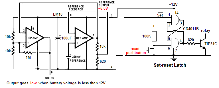
low battery detector.PNG
29.46 KB

Go to Top of Page

audioguru
Nobel Prize Winner

Canada
4218 Posts

Posted - May 01 2008 :  09:14:07 AM  Show Profile  Reply with Quote
The LM10 has a low current opamp and a low current voltage reference inside. The other circuit uses much more current with a lousy old 741 opamp and a zener diode to do the voltage detection.

The first circuit has a flip-flop latch to keep the battery disconnected when its voltage rises when its load is disconnected.
The second circuit will detect a low battery and disconnect it or turn off the inverter's oscillator. Then it will detect the battery voltage rising without a load and connect it. It will turn on then turn off over and over.

The TIP31C is a power transistor that can activate then disconnect a high current relay that applies power to the inverter.
The second circuit has a small low current transistor that stops the CD4047 to stop the inverter.

The high current of the 741 opamp and zener diode in the second circuit needs re-design of the 100 ohm resistor and 16V zener diode to power them and protect them from voltage spikes.
The low current of the first circuit allows it to be powered from the 100 ohm resistor and 16V zener diode with the CD4047.

Two gates of the CD4001 are used for the modified sine-wave logic and the remaining two gates are used for the flip-flop latch.
Go to Top of Page

pebe
Nobel Prize Winner

United Kingdom
1078 Posts

Posted - May 02 2008 :  07:09:05 AM  Show Profile  Reply with Quote
Change the 330K resistor to 47K
Go to Top of Page

pebe
Nobel Prize Winner

United Kingdom
1078 Posts

Posted - May 02 2008 :  10:54:27 AM  Show Profile  Reply with Quote
The circuit should work as it is. Once the battery is cut off its voltage will have to rise to about 18V before the circuit will cut in again.

BTW. Your posts would be much easier to read if you did not write in COLORS.

Edited by - pebe on May 02 2008 10:57:25 AM
Go to Top of Page

audioguru
Nobel Prize Winner

Canada
4218 Posts

Posted - May 02 2008 :  1:32:09 PM  Show Profile  Reply with Quote
quote:
Originally posted by pebe

The circuit should work as it is. Once the battery is cut off its voltage will have to rise to about 18V before the circuit will cut in again.

Then the circuit will work only one time and never work again.
The circuit needs to have a reset pushbutton like my flip-flop circuit has.
The pushbutton in my circuit has a low current so a switch with gold contacts should be used. The gold plated contacts cost the same or pennies more than high current silver that corrodes and doesn't work with low currents.

I realize that one of my circuits uses a CD4001 quad NOR IC and the other circuit uses a CD4011 quad NAND IC. It wouldn't be difficult to change one to the other so a single logic IC can be used.

The LM10 in my circuit performs exactly the same function as the circuit with the lousy old 741 opamp. The LM10 doesn't have a 200mV battery. It has a 200mV adjustable voltage reference circuit plus an opamp inside.

The MJ11032 is a darlington that has a much higher voltage drop than a 2N3055 power transistor. The circuit should be re-designed for it.
Power Mosfets should be used instead.

You are talking about a lot of power. A 12V car battery will boil or explode when it tries to drive such a powerful load. Where will you get the huge custom-made transformer? Rediculous.

Download Attachment: 
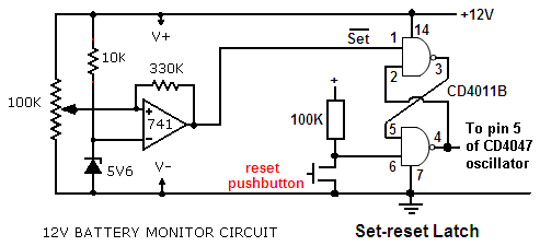
low battery cutoff again.PNG
10.26 KB

Go to Top of Page

senahia
New Member

Ghana
2 Posts

Posted - May 02 2008 :  1:35:53 PM  Show Profile  Reply with Quote
sir i will be very happy if you can send me schmatic diagram of 12vdc to 240vac inverter with solar and lead acide battery supplying the inverter for my project work please help me
Go to Top of Page

audioguru
Nobel Prize Winner

Canada
4218 Posts

Posted - May 02 2008 :  3:22:54 PM  Show Profile  Reply with Quote
Hi Senahia,
We have many schematics for inverters in this foum. Some use old transistors and others use new efficient Mosfets. Some are 100W and others are almost 1000W.
Some have a square-wave outputs that don't power many electronic products. Some are modified sine-wave that is like most inverters in stores. Pure sine-wave inverters are too complicated for a forum.
You don't say what you want.

Solar power is a separate topic. Battery chargers are also a separate topic.
Go to Top of Page

audioguru
Nobel Prize Winner

Canada
4218 Posts

Posted - May 03 2008 :  11:22:50 AM  Show Profile  Reply with Quote
Juan,
If you use a single CD4001 or CD4011 then the logic circuit must be re-designed for it.

Please look at the datasheet for the MJ11032.
With an output current of 25A its input current is only 250mA for it to have a max saturation voltage loss of 2.5V and it will dissipate a max average power of 31.3W. The 0.1 ohm emitter resistor will have a voltage loss of 2.5V and also dissipate an average power of 31.3W.
Four MJ11032 darlingtons on each side will have a max total input current of 1A and can be driven with a TIP31 or TIP41. They will add to the saturation voltage loss.
So nearly half the power from the battery is wasted.
Go to Top of Page

audioguru
Nobel Prize Winner

Canada
4218 Posts

Posted - May 04 2008 :  12:07:37 AM  Show Profile  Reply with Quote
quote:
Originally posted by JUAN DELA CRUZ
If I will use only one MJ11032 (each side) to simulate the use of "8" 2N3055
And drive with TIP41.

Four 2N3055 transistors are good for about 50A. One MJ11032 darlington is good for about 50A. The TIP41 will have a max base current of about 50ma so another transistor is needed.

The total max saturation voltage loss will be about 5.7V which is too high. The max output power will be only about 340W if a lower voltage transformer is used. a lot of battery power is wasted if the transistors have low gain.

quote]The remaining components will be the same excluding the EMITTER Resistor?[/quote]
Yes, the emitter resistors are used to match the conduction of different transistors and are not needed with only a single transistor on each side.
Go to Top of Page

audioguru
Nobel Prize Winner

Canada
4218 Posts

Posted - May 05 2008 :  11:50:28 AM  Show Profile  Reply with Quote
Welcome to 1978. Transistors are a poor choice for a high current switching circuit compared to modern Mosfets.
The BUT100 is the most powerful transistor I have ever seen. The two major electronics parts distributors in America have never seen it either. Maybe it is no longer made.

The transistors are not saturated switches, they are in a darlington configuration where their base-emitter voltages add to create a total voltage loss:
The max VBE for a BUT100 is 1.4V at 50A.
The max VBE for an NTE43 is about 1.2V at 2.5A.
The max VBE for a 2N2222 at 250mA is about 1.4V.
The total max voltage loss is 4.0V.

All transistors are different. You might be lucky and get some with high gain. Then the voltage loss is about 3.0V.

A "12V" battery is 12.8V to 13.8V when fully charged. So the pulses to the transformer will be 8.8V to 10.8V.
When the battery voltage drops to about 12.0V when it is nearly dead then the pulses to the transformer will be from 8.0V to 9.0V.

The transformer might be good and not have much loss, or it might be cheap and have a high loss.
In order for it to produce a modified sine-wave the low voltage winding must be rated for 0.707 times its ordinary voltage rating.
Use an 8V-0V-8V transformer.

The BUT100 transistors do not need an emitter resistor because there is only one transistor on each side.
The other two resistors and diode are needed on each side.
Go to Top of Page

audioguru
Nobel Prize Winner

Canada
4218 Posts

Posted - May 06 2008 :  12:52:21 AM  Show Profile  Reply with Quote
You need to re-design the set-reset latch so it can use the unused gates of the CD4001. It is designed for a CD4011 now.
Go to Top of Page

audioguru
Nobel Prize Winner

Canada
4218 Posts

Posted - May 06 2008 :  08:54:57 AM  Show Profile  Reply with Quote
The NTE180 is PNP not NPN so won't work in this circuit. The NTE181 is an NPN but its spec's stop at only 7.5A.
NTE transistors do not have full spec's because they are "replacements" for standard transistors that have full spec's.
The Japanese transistor will be fine as a pre-driver transistor.

The low battery cutoff circuit doesn't need the TIP31 and relay. Its output can stop the oscillator in the CD4047.

I don't think the set-reset latch should connect to pin 5 of the CD4047 because then one output will keep the transistors turned on and blow the fuse. I remember in January we discussed using a CD4025 three input NOR in the modified sine-wave circuit and the 3rd inputs are used to turn off all the transistors.

The transformer needs only one resistor in series with a capacitor at the output. The values depend on the transformer since every transformer is different. You attach an oscilloscope to the output and adjust the values so that the voltage spikes are reduced without a load.
Go to Top of Page

osama madni
New Member

Pakistan
3 Posts

Posted - May 07 2008 :  09:44:53 AM  Show Profile  Send osama madni a Yahoo! Message  Reply with Quote
how i change transformer plz help me and capacitor
Go to Top of Page

osama madni
New Member

Pakistan
3 Posts

Posted - May 07 2008 :  09:59:25 AM  Show Profile  Send osama madni a Yahoo! Message  Reply with Quote
sir i have a problem with transformer and capacitor in my envirement there is not found such capacitor
Go to Top of Page
Page: of 63 Previous Topic Topic Next Topic  
Previous Page | Next Page
 New Topic  Reply to Topic
 Printer Friendly
Jump To:
Aaron's Homepage Forum © 1995-2020 AARONCAKE.NET Go To Top Of Page
This page was generated in 0.17 seconds. Snitz Forums 2000