| Home > RX-7 > Tech/Mods > Mods > Megasquirt > Building and/or Modding The Megasquirt MS1/MS2 |
| Home > RX-7 > Tech/Mods > Mods > Megasquirt > Building and/or Modding The Megasquirt MS1/MS2 |
These instructions apply to Megasquirt 1 and Megasquirt 2 only. If you are installing an MS3X on your RX-7, then you should skip this page and look at the MS3X instructions. Or feel free to read this page just for the awesome info contained. Either way is fine with me.
Whether you choose to build your Megasquirt MS1/MS2 from a kit or buy one preassembled, modifications are necessary to adapt it to the RX-7. A 2nd VR circuit needs to be added to read the stock CAS, a small modification is needed for the BAC valve, and a transistor must be added to enable control of the e-fan relay. If you have never assembled an electronics kit before it is probably a good idea to purchase a preassembled Megasquirt. Buying assembled and tested means you don't have to spend 8 hours behind the soldering iron or worry that you messed up the circuit if it doesn't work. Then again, buying a preassembled 'Squirt means that you don't get to enjoy spending 8 hours behind the soldering iron. If you do chose to assemble the 'Squirt out of a kit you will also need to purchase a Megasquirt Stimulator as it will make bench testing much easier. Honestly, you should have a Stimulator anyway because it will make things like loading firmware a lot easier. The instructions on this page assume you have a Stimulator when they instruct you to load firmware.
Skip this section if you have purchased an assembled Megasquirt. Assemble your kit according to the assembly directions in the Megamanual. Much of the assembly is standard but during assembly it is convenient to apply a few of the necessary modifications. Here's a list of what needs to be done during assembly:
At this point your Megasquirt is assembled and should run using the Stimulator. You can now move on to modifying it for the RX-7.
If you have purchased your Megasquirt fully assembled then it will probably have come configured to trigger from the coil/points with no ignition output selected. Most vendors do this so that the 'Squirt will run on the Stimulator. If you have a Stim, you should be able to run the Megasquirt at this point. If you don't have a Stim, don't worry because assembled 'Squirts are tested by the vendor. A Stim is still quite a handy item to have though. Since most assembled Megasquirts are assembled to the instructions in the Megamanual it is likely missing the PWM Idle Valve mod. This and other mods will be added below.
The stock Bowling & Grippo firmware loaded onto Megasquirt CPUs from the factory will run the rotary, but it will run fuel only and without a lot of the features we depend on (such as staged injection). It is therefore necessary to load the Megasquirt and Spark Extra (MSnSE) firmware.
At this point, if you have not already downloaded TunerStudio MS, do so now and install it. The free version will suffice for now however you may want to upgrade to the paid version when you start tuning as only the paid version can autotune the VE table.
Connect your Megasquirt to the Stimulator and make sure that it is responding to inputs. The first time you run TunerStudio you will need to create a project for your ECU. For the time being I'd suggest creating a temporary project and just accepting the defaults. DIYAutoTunwe has some great generic TunerStudio setup instructions.
Now you'll need to upgrade the firmware on the Megasquirt to the latest version of MSExtra/MSnS-Extra.
If you are using an MSI, see the MSnS-Extra Software Manual for instructions on low to load the latest version of MSI/Extra.
MSII users should see the MS2-Extra Software Manual for installation instructions for the latest version of MS2/Extra.
Don't bother following the instructions on the above websites to configure the Megasquirt to your engine or configure MegaTune/TunerStudio. We'll do that later.
If you do not have a Stimulator then you will need to wait until the car is wired to upgrade your firmware. This is a lot more complicated and can be very annoying. You must leave the ignition coils disconnected until the firmware is loaded and the Megasquirt is fully configured if you take this approach. I recommend purchasing a Stimulator.
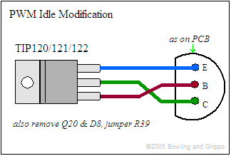
You will need to remove the following components: Q4, Q20, D8. Use a vacuum desoldering tool to carefully remove all solder from the pads of each component then alternately heat the legs while you carefully pull each component out. If you have never desoldered before, then see How To Desolder. Be very gentle and do not damage the pads, especially of Q4.
Mount the new transistor (the TIP120 or equivalent) on the rear wall of the casing, where the DB37 is located. I put it in the top left as shown in the picture. Make sure to use a mica insulator and plastic screw, or insulate a metal screw with a plastic insulator ring (available at an electronics store).
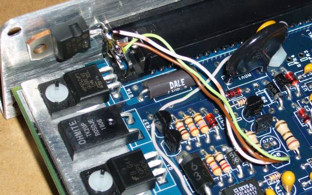
Use a spare component lead or a bit of wire to jumper R39.
Now wire the TIP120 (or equivalent) in place of Q4 as per the diagram below:
You may want to skip the application of heatsink grease and keep the mounting screw loose as the board has to come out in the next step. The image shown here of the completed mod shows the transistor not yet mounted as further mods will be applied.
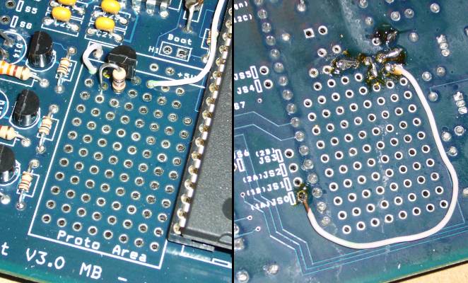
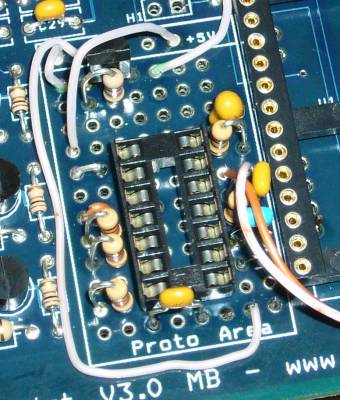
As shown in the picture below, add a 2N3904 (or equivalent) transistor and 1K resistor to the top left of the prototype area. Place your components in the minimum space you can to avoid taking up more area on the prototype board then necessary. There is still another more complicated circuit to add and you don't want to run out of space. The top left is generally the best location and if you are careful, your transistor and resistor will only take a 5 hole by 2 hole area.
Connect it as per the diagram below:
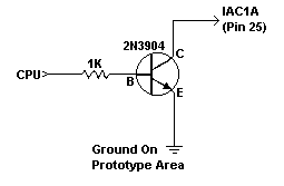
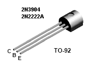
Here is the pinout of the 2N3904 and 2N2222A transistor:
Connect the line marked "CPU" to JS0 (X2) for both MS1 and MS2 applications.
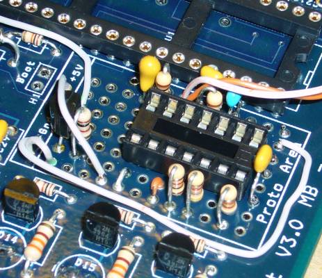
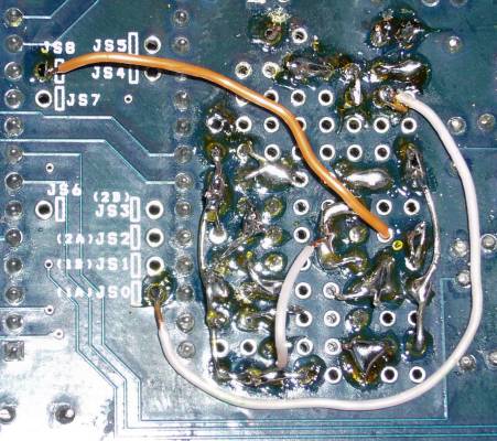
Position your socket for the LM1815 just a bit lower then the middle of the prototype area, and in the center horizontally. Now build your circuit around the socket according to the schematic below. It is helpful to run a bare ground wire down the right side of the circuit and a bare +5V wire down the left side. Solder on all components in roughly the location of the schematic and then connect them together with hookup wire or spare component leads. Be careful not to bridge solder pads on the IC or around adjacent components.

There is a slight variation you need to make to the circuit depending if you are running an MS1 or an MS2. MS1 users should build the circuit with the red section which puts the LM1815 into R/C timer mode. MS2 users need to build the green section (basically directly grounding ping 14) to put the LM1815 into zero crossing mode.
A completed circuit is shown below:
If you are using MSI, connect "OUT" to pin 11 (JS8 on the board) of the CPU. If you are using MSII on the 1.x MS2Extra firmware, connect to JP4 which is on the CPU board. If you are using version 2.x of MS2Extra and MSII, connect to JS10 (pin 17 on the CPU).
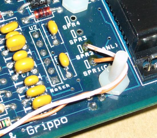
Connect SPR1 (pin 3 of the DB37 connector) to "CAS" using a bit of hookup wire. Connect SPR2 (pin 4 of the DB37) to the ground point of the LM1815 circuit with a bit of hookup wire.
Finally, the Megasquirt needs to be configured to accept an input on its built in VR circuit. Remove any jumper at XG1 and XG2. Remove the jumper from OPTOIN to TACHSELECT if present. If TSEL is set to OPTOOUT, remove that jumper as well. Jumper VRIN to TACHSELECT. Now jumper TSEL to VROUTINV. The last step is to turn both of the pots fully counterclockwise. Use a small screwdriver and go slowly. It takes a lot of turns to reach the end. At the end there will either be an indent or a click. When you reach that point, back off a few turns, counting the number of turns you go. Then go forward again, stopping just before the click point (count your turns and stop just before your count ends).
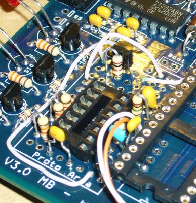
Now run lengths of hookup wire as follows:
You can see these wires are ran along the bottom of the board, well away from the VR circuit.
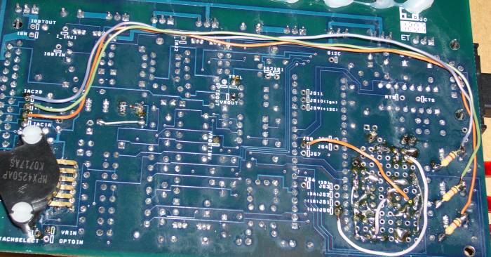
Now, secure all your loose wires to the board using hot glue or silicon. This will prevent them from vibrating while the vehicle is in operation and greatly reduce the chance of failure.
Whew! That sounds like a lot of work but actually can be accomplished quite quickly if you have a bit of soldering and electronics experience. If you don't, it's also not too difficult if you follow the instructions closely. Now the Megasquirt has been fully modified to run the rotary using the 2nd gen CAS and coils so it is ready to be installed in the car.
Back To Mods Page | Mail Me | Search | ![]()