| Home > RX-7 > Tech/Mods > Mods > Megasquirt > Modding And Setting Up Megasquirt MS3X |
| Home > RX-7 > Tech/Mods > Mods > Megasquirt > Modding And Setting Up Megasquirt MS3X |
These instructions apply to Megasquirt MS3X. If you are installing a MS1 or MS2 on your RX-7, then you should instead look at the MS1/MS2 instructions. Or read this page and see what you're missing with by using an older Megasquirt.
Unlike previous Megasquirts, MS3X requires no board mods and likely no harness mods to run the rotary. MS3-Pro requires no changes so if you have an MS3-Pro, just skip along to the next section.
The only thing required to configure the MS3X hardware for the rotary is to set the appropriate jumpers on both the mainboard and the MS3X expander. You're going to have to access the mainboard so you'll need to remove the Megasquirt from its case. Remove the jackscrews from both DB37s, then remove the 4 screws on each face plate. Remove the face plate from the DB37 side, then slide the cover off. Note that the Expander board is slipped into slots on the inner sides of the top half of the case so you will likely need to hold it in place using your thumbs against the DB37 as you slide the case off. Now disconnect the Expander board by removing the two ribbon cables and set it aside.
On the main board, set the following jumpers:
| JP1 | 1-2 |
| J1 | 3-4 |
| XG1/XG2 | Off |
This jumper configuration sets the board up to accept a tach signal on the VR conditioner (JP1) and then send the output of that conditioner to the CPU (J1). If you want to learn more about the jumpers and their various settings, check out the V3.57 main board schematic. Incidentally XG1/XG2 doesn't really matter in this configuration, I always just set it off when using the VR conditioner as to avoid confusion when looking at the board.
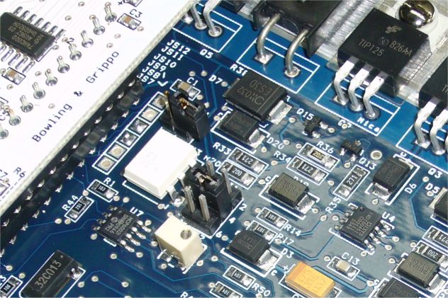
This image shows jumpers XG1/XG2 and J1. Note their location beside the CPU daughtercard.
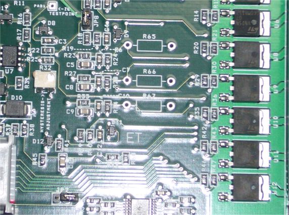
This image shows jumper J1 (yep, it's actually named J1 when there is already a JP1...just to be confusing I guess) located to the left of the DB37.
Set the mainboard aside and grab the Expander board. There are two jumpers on the expander board which need to be set. Set them as the following:
| JP7 | Off |
| JP8 | On |
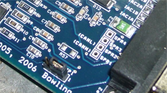
In the image below you can see JP8 located at the top left (just under the B&G logo, not shown) and JP7 located at the bottom left just beside the ribbon connector.
The last step in preparing the boards is to turn all of the pots fully counterclockwise. There are two sets of two pots each: two on the mainboard and two on the Expander board. Use a small screwdriver and go slowly. It takes a lot of turns to reach the end. At the end there will either be an indent or a click. When you reach that point, back off a few turns, counting the number of turns you go. Then go forward again, stopping just before the click point (count your turns and stop just before your count ends).
Finally, you can put everything back together. Slip the mainboard and CPU back into the case, making sure to line it up with the correct slot. Connect up the Expander board (both ribbon cables) and then slide the top half of the case on, making sure the Expander board engages the correct slots as well. Now screw the side cover plate back on and screw back in the jackscrews on the DB37s.
The MS3X is now prepped for rotary use.
Some MS3X harnesses don't include shielded wire on their trigger input. While this is generally OK for hall sensor use, our VR sensors output a far lower signal at low engine speeds and are far more susceptible to noise. Because of this, we need to replace the unshielded wire with two conductor shielded wire if necessary. So take a look at your MS3X harness and check to see if the "CAM" (VR, hall) input on pin 32 is a shielded pair wire. As most MS3X harnesses are by now, you should be good to go.
If that wire is a normal unshielded wire, typically green and labelled "CAM INPUT", we need to replace it with shielded cable.
First, remove the cover from the DB37. Cut any electrical tape off of the harness and slip back any loom. With all the wires exposed, separate out the CAM INPUT (normally dark green, pin 32) wire. Cut that wire about an inch away from the DB37 and then strip off about 1/4" of insulation.
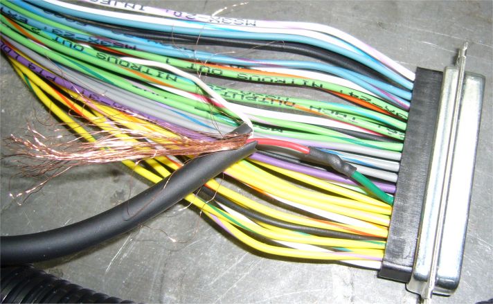
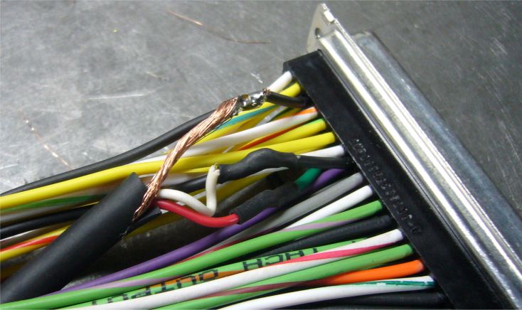
Working now on your shielded pair wire, strip enough of the outer insulation back so that you can separate out the wires and shield. Braiding the shield will help a bit with keeping it under control and out of the way. Strip about 1/4" from one of the wires and make sure to note the colour as you will need this info later. Slip on some heatshrink and solder this wire to the green wire. Clean off any excess solder flux and shrink your heatshrink tubing. You should end up with roughly what's shown in the image above.
Find two black ground wires. One will be used to connect the cable shield and another will be used as a ground return for the VR sensor. Perform the exact same cut and solder operation on one of the ground wires, this time connecting the 2nd shielded wire and continuing the ground wire out of the connection. Make sure to keep track of which wire you connect because this will be the negative connection to the VR sensor. I find it convenient to simply strip a bit of insulation off of the ground wire with a knife instead of cutting the wire. Then wrap the 2nd shielded wire around it, solder, and slip a bit of heatshrink all the long way down the black wire from the very end.
Finally, strip a bit of insulation off of the second black wire you found and solder on the shield. The result should look something like below.
That's it, the harness is now modified. You can bundle the wires a few inches from the connector with electrical tape as a stress relief and then reassemble the connector body. Just make sure not to pinch any of the wires while tightening down the body screws.
Any MegaSquirt mainboard harness purchased from DIYAutoTune will at this point have a dual conductor shielded cable installed for the mainboard VR circuit. However, if you happen to have a harness which does not, then you will need to perform this exact same modification to the mainboard harness connector. Connect one wire in the shielded cable (VR+) to pin 24. Connect the second wire (VR-) to pin 2. Then connect your shield ground to one of the black ground wires (such as pin 1). Keep track of which wire goes where because you will need this information later on.
With the MS3X set up and the harness modified, we can move back to working on the car itself.
Back To Mods Page | Mail Me | Search | ![]()