| Author |
 Topic Topic  |
|
Ferraro1
New Member
USA
1 Posts |
 Posted - Jul 27 2011 : 02:59:29 AM Posted - Jul 27 2011 : 02:59:29 AM


|
| AH! But this circuit does work!!! I am having some problems with frequency here, so I will attempt to alter the RC network a little. Tantalum capacitors are hard to find in the denominations were using here, might have to parallel a bunch up. I do see the reason for tantalum caps here, at the cost of several electrolytic explosions. :) I did scope the output on a digital o scope and there sure is a bunch of high frequency crap, might try a little low-pass and see if I can't reject some of it. Wanted to mention also that I wired a 12.6V CT XFMR rather than the 24v as shown, and of course at the cost of output current, but with the 3055 nPn s I'm using it could be upgraded easily with either a hand wound XFMR or a salvaged one. I'll let you know just how much I can push out, also consider using an in line fuse here. Thanks for thus we're going to go with a solar application for this. |
 |
|
|
audioguru
Nobel Prize Winner

Canada
4218 Posts |
Posted - Jul 28 2011 : 08:09:21 AM
|
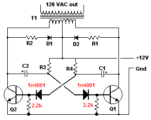
The capacitors blow up because they have the very high current of the transistors having avalanche breakdown of their emitter-base reverse biased junctions in them. The avalanche breakdown causes most of the power to be wasted (which blows the capacitors) so the remaining output power is very low. The transistors have a forward base current that is too low to make much power anyway.
Silicon transistors should never be used in this multvibrator circuit when the supply is higher than 7V to eliminate avalanche breakdown (or maybe re-designed with extra diodes). Maybe this circuit originally used old germanium transistors. |
|
|
|
pebe
Nobel Prize Winner
United Kingdom
1078 Posts |
Posted - Jul 28 2011 : 12:55:52 PM
|
quote:
Tantalum capacitors are hard to find in the denominations were using here, might have to parallel a bunch up. I do see the reason for tantalum caps here, at the cost of several electrolytic explosions
I have found tantalums available up to 200uF. But tants are polarized, so what makes you think they will stand reverse voltage better than electrolytics?
|
|
|
|
audioguru
Nobel Prize Winner
Canada
4218 Posts |
Posted - Aug 22 2011 : 2:51:01 PM
|
The polarity of the capacitors has been recently corrected on the schematic.
Their polarity is reversed only about 0.6V which will not damage an electrolytic capacitor.
But there is a very high current in the capacitors that damages them. One capacitor is charged to about 24V (transformer action causes a transistor collector to swing to +24V) then this transistor turns on and its collector saturates and drives the positive end close to ground which tries to drive the negative end to -24V. But the emitter-base junction of this transistor has avalanche breakdown (like an 8V zener diode) at a high current. The high current is in the capacitor.
The avalanche breakdown of the emitter-base junctions can be prevented by adding diodes in series with each base. Then each base will need a 2.2k resistor to ground to make it turn off when it should be turned off.
The timing will need to be re-adjusted.
The base current is low so the output power will be low.
Download Attachment:  bad inverter corrected.PNG bad inverter corrected.PNG
6.96 KB
 |
|
|
|
JUAN DELA CRUZ
Mad Scientist

Philippines
476 Posts |
Posted - Aug 23 2011 : 06:05:16 AM
|
@audioguru
Hi audioguru! Its been a long time :-)
Do the inverter circuit above (with the correction) is functioning now?
How much power it can provide from a 100AH car battery? |
juan dela cruz
Penniless INVENTOR |
|
|
|
audioguru
Nobel Prize Winner
Canada
4218 Posts |
Posted - Aug 23 2011 : 11:26:27 PM
|
Hi again, Juan.
My corrections to the inverter will result in a base current of only about 66mA. Then the transistor collector current will be only 660mA if the transistors have minimum current gain when saturated.
660mA at 120VAC output is a power of only 79.2W. Some transistors with a high current gain might provide an output power of 158W.
The extremely simple circuit produces a square-wave output that many electronic devices cannot use.
Its output voltage is not regulated so it is too high with a freshly charged battery and light load and is too low when the battery is running down and the load is heavy. |
|
|
|
JUAN DELA CRUZ
Mad Scientist
Philippines
476 Posts |
Posted - Sep 01 2011 : 1:35:22 PM
|
Well it is a good choice for low power application where in voltage regulation is not the priority.
BTW, what is transistor that can be use to increase its output power a little bit? (that you have mentioned with High Gain?)
Thanks audioguru |
juan dela cruz
Penniless INVENTOR |
|
|
|
audioguru
Nobel Prize Winner
Canada
4218 Posts |
Posted - Sep 02 2011 : 09:28:36 AM
|
quote:
Originally posted by JUAN DELA CRUZ
BTW, what is transistor that can be use to increase its output power a little bit? (that you have mentioned with High Gain?)
Hi Juan,
Inverters used power transistors many years ago. Today they use a little oscillator that drives power Mosfets. |
|
|
|
JUAN DELA CRUZ
Mad Scientist
Philippines
476 Posts |
Posted - Sep 04 2011 : 5:49:51 PM
|
http://www.edaboard.com/thread192166.html
Please click the link. (on the lower part of the discussion)
Guys, please assist me here.
I need to drive a power mosfets instead of BJT in the PWM inverter circuit (in the LINK)
What will be the change needed? I wiill be using a deep cycle batteries For approx. 1KW output.
Thanks. |
juan dela cruz
Penniless INVENTOR |
Edited by - JUAN DELA CRUZ on Sep 04 2011 11:52:26 PM |
|
|
|
pebe
Nobel Prize Winner
United Kingdom
1078 Posts |
Posted - Sep 05 2011 : 11:44:36 AM
|
| I think the designer must be living in Dreamland if he thinks he can get 5KW out of that output stage. |
|
|
|
JUAN DELA CRUZ
Mad Scientist
Philippines
476 Posts |
Posted - Sep 05 2011 : 12:27:12 PM
|
quote:
Originally posted by pebe
I think the designer must be living in Dreamland if he thinks he can get 5KW out of that output stage.
Hi Pebe its been a long time!
Yeah I think the designer used a bank of batteries! 5Kw output is impractical due to losses using BJTs.
I was looking for just approx. 1Kw output from a Deep cycle batteries.
I need to drive a Power Mosfets instead of BJT.
Do you think the driver ckt. (in the LINK) can drive power mosfets? What wiill be the adjustment needed?
Please assist me.
Thanks. |
juan dela cruz
Penniless INVENTOR |
|
|
|
audioguru
Nobel Prize Winner
Canada
4218 Posts |
Posted - Sep 05 2011 : 12:47:36 PM
|
Most power Mosfets need a gate to source voltage of 10V to completely turn on.
That circuit has the IC powered by only 8V and it has losses so the gates of Mosfets will not be fed enough voltage. |
|
|
|
JUAN DELA CRUZ
Mad Scientist
Philippines
476 Posts |
Posted - Sep 06 2011 : 11:46:02 AM
|
quote:
Originally posted by audioguru
Most power Mosfets need a gate to source voltage of 10V to completely turn on.
That circuit has the IC powered by only 8V and it has losses so the gates of Mosfets will not be fed enough voltage.
So, the IC should be powered by at least 12V regulated or higher to drive power mosfets?
How about the driver section.. is there any adjustment needed?
Thanks. |
juan dela cruz
Penniless INVENTOR |
|
|
|
audioguru
Nobel Prize Winner
Canada
4218 Posts |
Posted - Sep 07 2011 : 12:07:59 AM
|
The SG3524 IC drives bipolar junction transistors very well but drives Mosfets poorly.
Complementary emitter-followers can be added to drive Mosfets but they produce additional gate voltage loss. |
|
|
|
JUAN DELA CRUZ
Mad Scientist
Philippines
476 Posts |
Posted - Sep 08 2011 : 04:58:43 AM
|
quote:
Originally posted by audioguru
The SG3524 IC drives bipolar junction transistors very well but drives Mosfets poorly.
Complementary emitter-followers can be added to drive Mosfets but they produce additional gate voltage loss.
Ok, so complementary emitter-follower is needed in the drive section. But, using IT gate voltage loss is added? Why is that?
Can you show how it can be attach to the driver ckt?
|
juan dela cruz
Penniless INVENTOR |
|
|
|
Topic |
|