| Author |
 Topic Topic  |
|
audioguru
Nobel Prize Winner

Canada
4218 Posts |
 Posted - Sep 08 2011 : 1:54:06 PM Posted - Sep 08 2011 : 1:54:06 PM


|
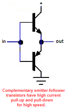
A complementary emitter-follower has a 0.7V loss when it goes high and a 0.7V loss when it goes low.
The output of an SG3524 needs a pullup resistor then it can drive the complementary emitter follower. The complementary emitter follower can provide plenty of current to quickly charge and discharge the high gate capacitance of a Mosfet.
Download Attachment:  complementary transistors.PNG complementary transistors.PNG
14.12 KB
 |
 |
|
|
JUAN DELA CRUZ
Mad Scientist

Philippines
476 Posts |
Posted - Sep 08 2011 : 6:05:26 PM
|
quote:
Originally posted by audioguru
A complementary emitter-follower has a 0.7V loss when it goes high and a 0.7V loss when it goes low.
The output of an SG3524 needs a pullup resistor then it can drive the complementary emitter follower. The complementary emitter follower can provide plenty of current to quickly charge and discharge the high gate capacitance of a Mosfet.
Download Attachment: complementary transistors.PNG
14.12 KB
Thanks audioguru but chossing the exact value of components is my problem. Please help me to choose.
1. What value of complementary emitter-follower BJTs can you suggest me to use that can be added to the Driver circuit in the link that I provided?
(do you think 2N22222A & 2N29072A will enable to drive a lot of Power mosfets to have a power output of approx. 1.5KW from a bank of deep cycle batteries ?
2. How about the pull ups resistor value? (do you think a 10K resistor will do with a 2K2 series resistor with each power mosfets?)
Thanks. |
juan dela cruz
Penniless INVENTOR |
|
|
|
JUAN DELA CRUZ
Mad Scientist
Philippines
476 Posts |
Posted - Sep 08 2011 : 6:36:01 PM
|
@audioguru,
http://www.simplecircuitsandprojects.com/circuits/power-inverter-circuit-with-low-battery-shutdown1.html
I have found another circuit (similar to the first one but it has a low voltage shutdown circuitry) in the LINK (above) with a issue regarding with the IC supply (with 9V regulator) which is to low because of voltage loss right?
Do you think it work well esp. pull up resistor in that circuit disregarding the absents of enough voltage supply to the IC and complementary emitter-follower BJTs?
Thanks. |
juan dela cruz
Penniless INVENTOR |
|
|
|
JUAN DELA CRUZ
Mad Scientist
Philippines
476 Posts |
Posted - Sep 10 2011 : 06:39:21 AM
|
@audioguru,
(In Addition with my Query above)
http://www.simplecircuitsandprojects.com/circuits/power-inverter-circuit-with-low-battery-shutdown1.html
I have found another circuit (similar to the first one but it has a low voltage shutdown circuitry) in the LINK (above) with a issue regarding with the IC supply (with 9V regulator) which is to low because of voltage loss right?
Do you think it work well esp. pull up resistor in that circuit disregarding the absents of enough voltage supply to the IC and complementary emitter-follower BJTs?
Thanks. |
juan dela cruz
Penniless INVENTOR |
|
|
|
pebe
Nobel Prize Winner
United Kingdom
1078 Posts |
Posted - Sep 10 2011 : 11:31:54 AM
|
quote:
Originally posted by JUAN DELA CRUZ
@audioguru,
(In Addition with my Query above)
http://www.simplecircuitsandprojects.com/circuits/power-inverter-circuit-with-low-battery-shutdown1.html
I have found another circuit (similar to the first one but it has a low voltage shutdown circuitry) in the LINK (above) with a issue regarding with the IC supply (with 9V regulator) which is to low because of voltage loss right?
Do you think it work well esp. pull up resistor in that circuit disregarding the absents of enough voltage supply to the IC and complementary emitter-follower BJTs?
Thanks.
Juan, you have been a long time developing your inverter.
I reckon that by the time you get it finished, your area will be well served by a mains electricity supply powered by a nuclear reactor.  |
|
|
|
JUAN DELA CRUZ
Mad Scientist
Philippines
476 Posts |
Posted - Sep 12 2011 : 05:59:05 AM
|
quote:
Originally posted by pebe
quote:
Originally posted by JUAN DELA CRUZ
@audioguru,
(In Addition with my Query above)
http://www.simplecircuitsandprojects.com/circuits/power-inverter-circuit-with-low-battery-shutdown1.html
I have found another circuit (similar to the first one but it has a low voltage shutdown circuitry) in the LINK (above) with a issue regarding with the IC supply (with 9V regulator) which is to low because of voltage loss right?
Do you think it work well esp. pull up resistor in that circuit disregarding the absents of enough voltage supply to the IC and complementary emitter-follower BJTs?
Thanks.
Juan, you have been a long time developing your inverter.
I reckon that by the time you get it finished, your area will be well served by a mains electricity supply powered by a nuclear reactor.
LOL!!! Well Its been a habit for me building a power inverter to power appliances from batteries.
Due to component availability I desided to build again but now using PWM IC with feedback to ensure regulation.
But, I have some difficulties choosing the right components needed. I need to convert the circuit HERE: (http://www.edaboard.com/thread192166.html) I need to drive POWER MOSFETs instead BJTs. I need to include complementary emitter-follower BJTs to drive POWER Mosfets to have an OUTPUT of approx. 1.5KW from bank of Deep Cycle Batteries. (do you think 2N2222 & 2N2907 will do??? )
I need also to choose the right value of PULL UP RESISTOR needed to drive the complementary emitter-follower BJTs from SG3524 IC.
Please assist me here...
Thanks. |
Edited by - JUAN DELA CRUZ on Sep 12 2011 06:03:32 AM |
|
|
|
audioguru
Nobel Prize Winner
Canada
4218 Posts |
Posted - Sep 12 2011 : 11:57:14 AM
|
quote:
Originally posted by JUAN DELA CRUZ
@audioguru,
http://www.simplecircuitsandprojects.com/circuits/power-inverter-circuit-with-low-battery-shutdown1.html
I have found another circuit (similar to the first one but it has a low voltage shutdown circuitry) in the LINK (above) with a issue regarding with the IC supply (with 9V regulator) which is to low because of voltage loss right?
Do you think it work well esp. pull up resistor in that circuit disregarding the absents of enough voltage supply to the IC and complementary emitter-follower BJTs?
The circuit has many things wrong:
1) The gates of the Mosfets get only 6V instead of 10V. Then they might only partially turn on and get extremely hot.
2) With two 2.2k resistors in series turning on each Mosfet then they turn on very slowly (because they have a high capacitance) which causes them to get very hot.
3) The 10k resistor to ground on each side in series with the 2.2k gate resistor for each Mosfet turn them off extremely slowly which causes them to get extremely hot.
4) The designer has the LED connected backwards. |
|
|
|
JUAN DELA CRUZ
Mad Scientist
Philippines
476 Posts |
Posted - Sep 13 2011 : 01:54:35 AM
|
quote:
Originally posted by audioguru
quote:
Originally posted by JUAN DELA CRUZ
The circuit has many things wrong:
1) The gates of the Mosfets get only 6V instead of 10V. Then they might only partially turn on and get extremely hot.
2) With two 2.2k resistors in series turning on each Mosfet then they turn on very slowly (because they have a high capacitance) which causes them to get very hot.
3) The 10k resistor to ground on each side in series with the 2.2k gate resistor for each Mosfet turn them off extremely slowly which causes them to get extremely hot.
4) The designer has the LED connected backwards.
How about in this circuit: (http://www.edaboard.com/thread192166.html)
quote:
Originally posted by audioguru
A complementary emitter-follower has a 0.7V loss when it goes high and a 0.7V loss when it goes low.
The output of an SG3524 needs a pullup resistor then it can drive the complementary emitter follower. The complementary emitter follower can provide plenty of current to quickly charge and discharge the high gate capacitance of a Mosfet.
Download Attachment: complementary transistors.PNG
14.12�KB
Thanks audioguru but chossing the exact value of components is my problem. Please help me to choose.
1. What value of complementary emitter-follower BJTs can you suggest me to use that can be added to the Driver circuit in the link that I provided?
(do you think 2N22222A & 2N29072A will enable to drive a lot of Power mosfets to have a power output of approx. 1.5KW from a bank of deep cycle batteries ?
2. How about the pull ups resistor value?
Thanks. |
juan dela cruz
Penniless INVENTOR |
|
|
|
pebe
Nobel Prize Winner
United Kingdom
1078 Posts |
Posted - Sep 13 2011 : 02:22:21 AM
|
Juan,
A further problem with the circuit.
When Q8 conducts its collector will go negative. By auto-transformer action, the collector of Q7 will go positive, and D1 will fry ! Ditto for D2 when Q7 conducts. |
|
|
|
JUAN DELA CRUZ
Mad Scientist
Philippines
476 Posts |
Posted - Sep 13 2011 : 06:07:54 AM
|
quote:
Originally posted by pebe
Juan,
A further problem with the circuit.
When Q8 conducts its collector will go negative. By auto-transformer action, the collector of Q7 will go positive, and D1 will fry ! Ditto for D2 when Q7 conducts.
How about in this circuit? (http://www.edaboard.com/thread192166.html)
I need to include complementary emitter-follower BJTs to drive Power Mosfets instead. Do you think 2N2222 & 2N2907 will do? ..with a 1k pull up resistor from the IC?
 |
juan dela cruz
Penniless INVENTOR |
Edited by - JUAN DELA CRUZ on Sep 13 2011 08:59:02 AM |
|
|
|
audioguru
Nobel Prize Winner
Canada
4218 Posts |
Posted - Sep 13 2011 : 1:19:58 PM
|
Juan, the schematic you posted is too small to see.
It is the circuit at EDA board with the diodes that fry. Also it might have other problems.
It doesn't have pullup resistors since the outputs that are used from the IC are emitter-followers.
You can build the defective circuits that are shown on the internet and see them burn.
You need to learn about the basics of electronics so you can spot errors in circuits and so you can modify circuits. |
|
|
|
JUAN DELA CRUZ
Mad Scientist
Philippines
476 Posts |
Posted - Sep 13 2011 : 7:32:48 PM
|
quote:
Originally posted by audioguru
Juan, the schematic you posted is too small to see.
[quote]Originally posted by audioguru
Juan, the schematic you posted is too small to see.
It is the circuit at EDA board with the diodes that fry. Also it might have other problems.
It doesn't have pullup resistors since the outputs that are used from the IC are emitter-followers.
You can build the defective circuits that are shown on the internet and see them burn.
You need to learn about the basics of electronics so you can spot errors in circuits and so you can modify circuits.
I do have knowledge in electronics, but not that much that's why Iam asking for some assistance.
Ok how about this circuit?
http://www.simplecircuitsandprojects.com/circuits/power-inverter-circuit-with-low-battery-shutdown1.html
 |
juan dela cruz
Penniless INVENTOR |
Edited by - JUAN DELA CRUZ on Sep 13 2011 8:01:00 PM |
|
|
|
audioguru
Nobel Prize Winner
Canada
4218 Posts |
Posted - Sep 13 2011 : 11:19:15 PM
|
quote:
Originally posted by JUAN DELA CRUZ
Ok how about this circuit?
I discussed the errors of this circuit about 18 hours ago. The high resistor values in series with the gates of the Mosfets and the high values of the pullup and pull-down resistors cause the Mosfets to turn on and off very slowly (because their high gate capacitance takes a long time to charge and discharge by the high resistor values) causes severe heating of the Mosfets.
Mosfets need a 10 ohms to 47 ohms resistor in series with the gate to prevent high frequency oscillation. They need a high current drive to quickly charge and discharge their high gate capacitance. |
|
|
|
pebe
Nobel Prize Winner
United Kingdom
1078 Posts |
Posted - Sep 15 2011 : 07:16:52 AM
|
quote:
What value of complementary emitter-follower BJTs can you suggest me to use that can be added to the Driver circuit in the link that I provided?
(do you think 2N22222A & 2N29072A will enable to drive a lot of Power mosfets to have a power output of approx. 1.5KW from a bank of deep cycle batteries ?
Juan,
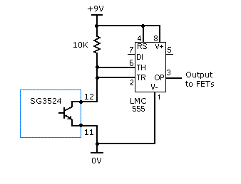
A better solution than complementary transistors would be to use this circuit. It uses the CMOS version of the 555 timer.
It can source and sink 100mA, and with a swing to 9V it will fully turn on the IRF3205 FETs.
Use an identical circuit for pins 13 and 14 of the SG3524.
Download Attachment: FET driver.GIF
3.44 KB
 |
|
|
|
JUAN DELA CRUZ
Mad Scientist
Philippines
476 Posts |
Posted - Sep 15 2011 : 7:01:11 PM
|
quote:
Originally posted by pebe
quote:
What value of complementary emitter-follower BJTs can you suggest me to use that can be added to the Driver circuit in the link that I provided?
(do you think 2N22222A & 2N29072A will enable to drive a lot of Power mosfets to have a power output of approx. 1.5KW from a bank of deep cycle batteries ?
Juan,
A better solution than complementary transistors would be to use this circuit. It uses the CMOS version of the 555 timer.
It can source and sink 100mA, and with a swing to 9V it will fully turn on the IRF3205 FETs.
Use an identical circuit for pins 13 and 14 of the SG3524.
Download Attachment: FET driver.GIF
3.44�KB
Great! Thanks sir for the circuit. . .
1. How many Power Mosfet do you think in can handle? ( I need approx. 1.5KW OUTPUT from bank of deep cycle batteries )
2. How about the "voltage loss issue" of the SG3524 accdg to audioguru?
3. *10 ohms series resistor will be enough to the gate of the Power Mosfet from PIN 3 of 555 Cmos chip?
Thanks. |
juan dela cruz
Penniless INVENTOR |
Edited by - JUAN DELA CRUZ on Sep 15 2011 7:08:33 PM |
|
|
|
Topic |
|