| Author |
 Topic Topic  |
|
liang2408
Apprentece

16 Posts |
 Posted - Feb 03 2008 : 06:57:20 AM Posted - Feb 03 2008 : 06:57:20 AM


|
Hi Sir,
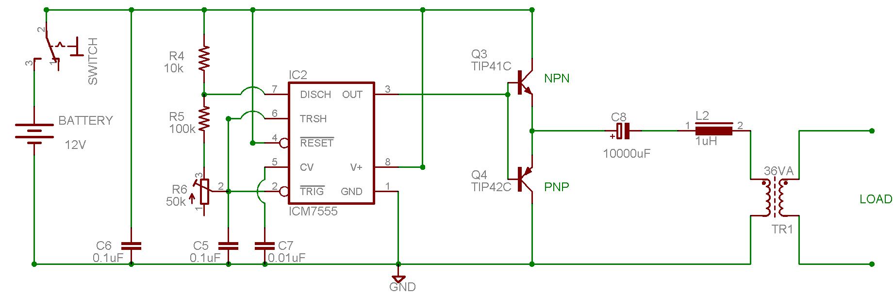
I have try to build a DC to AC inverter using 555 timer and a transformer that is 9-0-9V/230V and rated at 36VA. I managed to drive a light bulb of 11W. The attached file shows the schematics drawing of the inverter.
But when i didn't connect to any load and measured the input and output of the transformer, i got an input of 4.98Vrms on the primary side and 122Vrms on the secondary side. The output voltage is far below my requirement of 230VAC.
I hope you can give me some advises on the circuit and show me which part of the circuit to modify so as to achieve the desired output of 230VAC without any load connected. (Maybe i can use a center tap to boost up my input circuit.)
Sorry for your time and really appreciated for your help. Many thanks.
Download Attachment:  DC to AC Inverter.JPG DC to AC Inverter.JPG
85.25 KB
 |
|
|
audioguru
Nobel Prize Winner

Canada
4218 Posts |
Posted - Feb 03 2008 : 10:46:36 AM
|
Look at the datasheet for the 555 and of the transistors.
With a 12V supply, the output high voltage of a 555 without a load is +10.6V and is only +9.5V when fully loaded.
The output low voltage is 0.1V without a load and is +2.5V when fully loaded. So its output is only 7V p-p when fully loaded.
The transistors each have a loss of 0.7V without a load and a loss of up to 1V each with a load of 3A.
The output coupling capacitor has an internal resistance that causes a voltage loss when loaded and the choke also has a voltage loss.
The unloaded voltage feeding the transformer is 9.1V p-p which is 3.2V RMS.
Fully loaded, the voltage feeding the transformer is less than 1.8V RMS.
An ordinary multimeter has a huge error when reading the square-wave since it is calibrated for a sine-wave.
|
 |
|
|
mrgone
Nobel Prize Winner
USA
1176 Posts |
Posted - Feb 03 2008 : 10:49:26 AM
|
| There are a few thimgs that can go wrong. I don't know much about the ICM555 but are sure it has enough drive? What frequency is it producing? Those are good transistors you are using. Plenty of power for a light bulb & more but the configuration is horrible! The transformer should be feeding the collectors through a center tap and the emitters go to ground. Go search some PUSH-PULL amplifier circuits and you will see what I mean and if this is an attempt at a push-pull, you will also have to invert the 555 output so that you have two drives on the bases of both transistors. One in phase and out out of phase, or 180 degrees from each other. |
|
|
|
liang2408
Apprentece
16 Posts |
Posted - Feb 04 2008 : 01:12:41 AM
|
Hi,
Thanks for the reply. That circuit is not a purely a square wave as the presence of inductor and capacitor act as a filter.
The frequency that i generated from the 555 timer is 50Hz but it can only takes in +5V to +15V. Now mine concerned is that how am i able to produce a 230Vrms output without any load connected at the output of transformer. I hope that you are able to guide me on that schematics drawing on which part and how to modify it.
As i was thinking whether can i change my rating of my transformer or can i modify the circuit in such that it will function as centre tapped transformer. However, I do not know how to do it.
Regarding about the reply on the push-pull part, if i do that then where should i connect my inductor and capacitor?
Many Thanks |
|
|
|
mrgone
Nobel Prize Winner
USA
1176 Posts |
Posted - Feb 04 2008 : 09:07:29 AM
|
Well, did you look up any push-pull amps? You will know how to make it I think. I would raise my frequency up to about 50KHz but get amplifier right first. Also did you understand that the signal from your '555 must also have another signal 180 out of phase with it (two signals). If you don't use push-pull then you only need one transistor or you can parallel two of them but not like that. Let me find some examples.
OK I found one & modified a quick work up on other. The "Single example" has a square wave oscillator I left in to give you an idea of optimal frequency.
Download Attachment: Push-Pull example.GIF
4.2 KB

Download Attachment: Single example.GIF
6.03 KB
 |
|
|
|
liang2408
Apprentece
16 Posts |
Posted - Feb 04 2008 : 10:55:11 AM
|
Hi,
First of all i would like to thanks you for your advices. From your reply, i do understand what you mean. But for my circuit that i posted, i am using npn and pnp transistor and a dc capacitor. From my understanding, the dc capacitor will charge and discharge and thus able to make signal alternating. But it is just that the output is not able to get 230VRMS. Maybe it is what audioguru had stated about the losses.
If i need to use centre tapped tranformer, i need to use 2 same npn transistors and not npn with pnp. Hence, i assume that my circuit are not able to modify to be able to get the required output voltage.
Do you have any circuit that is workable to produced 230VRMS from 12VDC with an operating frequency of 50Hz? Could you kindly post it for me cause i need one badly.
Thank you for your time. |
Edited by - liang2408 on Feb 04 2008 10:57:03 AM |
|
|
|
audioguru
Nobel Prize Winner
Canada
4218 Posts |
Posted - Feb 04 2008 : 11:30:38 AM
|
The tiny 1uH inductor won't filter a 50Hz square-wave. Its inductance must be 10,000 times more to round the corners a little. Then it will have such a high resistance that you won't get any power output.
I see additional losses in your circuit.
You don't have a 555 that has an output current of 200mA. You have an ICM7555 which is a low current Cmos 555 that has an output current of only a few milli-amps with a high voltage loss. The TIP41 and TIP42 transistors need a base current of hundreds of milli-amps to switch 3A to produce 36VA.
There are hundreds of inverter circuits on the internet. Some work and others don't. I have posted a few that work in this forum.
A CD4047 is an oscillator IC that uses one resistor and one capacitor. It has two opposing square-wave outputs to drive two Mosfets that drive a center-tapped transformer. A Cmos gate IC can be added for the circuit to make a modified sine-wave.
|
|
|
|
mrgone
Nobel Prize Winner
USA
1176 Posts |
Posted - Feb 04 2008 : 12:47:14 PM
|
| Good Point! I would use MOSFETs. They tend to work better in this type of circuit don't they Guru? I think it has something to do with there tendancy toward non-linearity, so they are apt to produce more energy at various harmonics & spurious emittions. |
|
|
|
audioguru
Nobel Prize Winner
Canada
4218 Posts |
Posted - Feb 04 2008 : 2:46:52 PM
|
A Mosfet like an IRFZ44 (there are better ones)can conduct 35A with voltage loss of less than 1V.
A power transistor like a 2N3055 can conduct a current of only 10A with a massive 3.3A of base current and could have a voltage loss of 3V. |
|
|
|
liang2408
Apprentece
16 Posts |
Posted - Feb 04 2008 : 9:32:18 PM
|
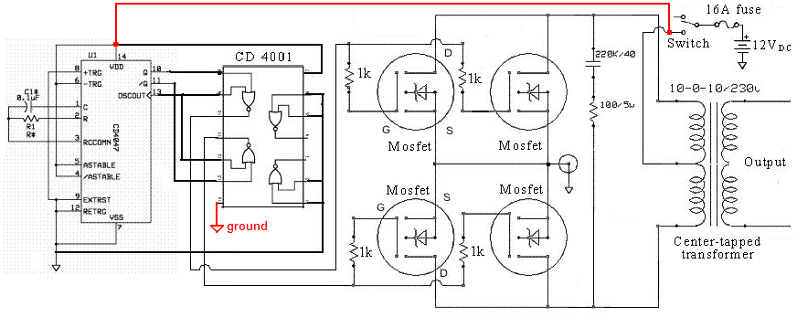
Hi audioguru,
I have decided to build the circuit with CD4047 together with CD4001 and IRFZ44. Hopefully, it i will be able to get the voltage and waveform that was required.
Just to clarify something, the resistor value that was input to CD4047, can i use a potentiometer instead of fixed value so as i can adjust the frequency accordingly? Furthermore, can i used a 9-0-9/230 with a rated of 36VA instead of 10-0-10/230 transformer. What will be the difference and if not, can i use a 12-0-12/230 transformer? Lastly, there is a capacitor that is connected in series to a resistor of 100/5W. What is the value of the capacitor, is it 220uF and also is it a AC or DC capacitor?
Anyway, thanks for your kindly response.
Download Attachment: 20081910308_Modified sine-wave inverter schematic.png
109.42 KB
 |
Edited by - liang2408 on Feb 04 2008 9:59:24 PM |
|
|
|
audioguru
Nobel Prize Winner
Canada
4218 Posts |
Posted - Feb 04 2008 : 11:43:03 PM
|
quote:
Originally posted by liang2408
Just to clarify something, the resistor value that was input to CD4047, can i use a potentiometer instead of fixed value so as i can adjust the frequency accordingly?
You can use a trimpot in series with a fixed resistor. A total of 47k will produce 50Hz and 39k will produce 60Hz.
quote:
Furthermore, can i used a 9-0-9/230 with a rated of 36VA instead of 10-0-10/230 transformer. What will be the difference and if not, can i use a 12-0-12/230 transformer?
A 36VA transformer is tiny for an inverter. It might be made with a cheating turns ratio to make up for a low output voltage when it is used for a step-down transformer. Then when it is reversed its output voltage will be too low. if you use a 12V-0V-12v transformer then the modified sine-wave voltage will be too much to low.
quote:
Lastly, there is a capacitor that is connected in series to a resistor of 100/5W. What is the value of the capacitor, is it 220uF and also is it a AC or DC capacitor?
The capacitor must be non-polarized and is 220nF which is 0.22uF.
The 12V feeding the ICs should have a 100 ohm resistor in series and a 16V zener diode to ground at the ICs. |
|
|
|
liang2408
Apprentece
16 Posts |
Posted - Feb 05 2008 : 08:22:25 AM
|
Hi audioguru,
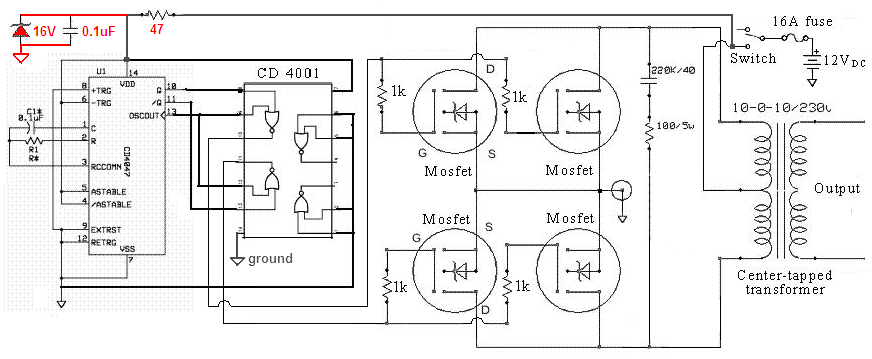
you mention that the 12V feeding the ICs should have a 100ohm resistor in series and a 16V zener diode to ground at the ICs. I managed to find a schematic diagram which is attached below. Is it the same connection that you mention for the zener diode and resistor?
if yes, but the diagram uses 47ohm as a resistor and not 100ohm so which one do i use? According to the electronic forum, i had read that there were 2 capacitors required for non-polarities. But according to the diagram, only the 220nF capacitor is required for the AC part but not for the 0.1uF capacitor which must have polarities.
Based on the diagram below, can i use 2 capacitors with a value of 0.1uF with polarities?
Lastly, is the diagram below shows the finalized diagram of the DC to AC inverter?
Download Attachment: Inverter.PNG
109.4 KB
 |
|
|
|
mrgone
Nobel Prize Winner
USA
1176 Posts |
Posted - Feb 05 2008 : 08:37:18 AM
|
| Man, that looks alot better! No, don't use polarized caps. They will explode. |
|
|
|
audioguru
Nobel Prize Winner
Canada
4218 Posts |
Posted - Feb 05 2008 : 11:45:00 AM
|
The schematic shows 4 Mosfets but a very low current fuse. Only 2 IRFZ44 Mosfets are good for an output up to about 400W. Then the fuse should be 40A.
A 47 ohm resistor feeding a 16V zener diode or a 100 ohm resistor doesn't make any difference.
I think Dennis made this circuit. |
|
|
|
liang2408
Apprentece
16 Posts |
Posted - Feb 05 2008 : 8:04:06 PM
|
Thank you audioguru and mrgone for your advises. I will build that circuit based on that schematics and hopefully it works. I will update you all the results.
Thank you |
|
|
|
liang2408
Apprentece
16 Posts |
Posted - Feb 15 2008 : 10:08:59 AM
|
Hi audioguru,
I have patched up the circuit and tested it. I obtained a constant DC output for the cd4047 at pin 13 instead of a square waveform(Clock pulse). But i managed to get a square waveform at the pin 10 and 11 which both are inverted of one another at a frequency of 50Hz. I had changed a new cd4047 IC chip but the results are the same, do you know what are the reasons behind it?
Thank you for your precious time. |
|
|
|
Topic |
|
 Push-Pull example.GIF
 Single example.GIF