| Author |
 Topic Topic  |
|
audioguru
Nobel Prize Winner

Canada
4218 Posts |
 Posted - Feb 15 2008 : 11:31:15 AM Posted - Feb 15 2008 : 11:31:15 AM


|
| Pin 13 of the CD4047 is supposed to be a square-wave at 100Hz. It feeds two gates of the CD4001. Maybe the two pins of the CD4001 are shorted to something. |
 |
|
|
liang2408
Apprentece

16 Posts |
Posted - Feb 16 2008 : 07:05:49 AM
|
Thanks audioguru, well i had troubleshooted the circuit many times but the configurations was correct. Anyway, i will check and update you again.
By the way, are all ground pins of the cd4047, cd4001 and Mosfet ground at the same point meaning that isolation are not required???
Thanks |
Edited by - liang2408 on Feb 16 2008 08:21:01 AM |
|
|
|
audioguru
Nobel Prize Winner
Canada
4218 Posts |
Posted - Feb 16 2008 : 09:19:19 AM
|
| The ground points of the entire circuit must be connected together or the circuit will not work. |
|
|
|
pearltorto
Apprentice

United Kingdom
99 Posts |
Posted - Feb 17 2008 : 5:09:11 PM

|
| say liang you wouldn't know a dr aziz? |
|
|
|
liang2408
Apprentece
16 Posts |
Posted - Feb 18 2008 : 01:50:58 AM
|
Hi pearltorto,
I do not know anyone of name dr aziz.
|
|
|
|
liang2408
Apprentece
16 Posts |
Posted - Feb 18 2008 : 02:00:58 AM
|
Hi audioguru,
I had managed to troubleshoot the circuit and for the cd4047 and MC14001BCP is used to replace cd4001 are both functioning properly. I power this circuit up via a DC power supply of 12V, but the moment when i power up, the DC supply jumps to 20.8V and drawing a current of 0.6A. I did not turn on my load at all. Then I tried to measured the output of the transformer. The output frequency showed a value of 73Hz and a jump to 236Hz. The output frequency of cd4047(pin 11 and pin 10) are both 50Hz. Also the output RMS voltage is 367VRMS. I am using a 9-0-9/230VAC rated of 36VA transformer. Why is it so?
If i switch on a light bulb that consume 11W rated at 230VAC, will the output of the transformer drops to 230VAC or will my load explode.
Pls help me out in this. Thank you |
Edited by - liang2408 on Feb 18 2008 02:06:03 AM |
|
|
|
liang2408
Apprentece
16 Posts |
Posted - Feb 19 2008 : 01:50:51 AM
|
Hi Master audioguru,
r u there??? i have another questions that is will the type of capacitors used affect the frequency of the output of the transformer despite having the same capacitance value? For my case, i am using polyester instead of ceramics capacitors and does it explain why i will obtain oscillating output frequnecy?
As for the raise in the DC supply of 20.8V, is it due to the transformer tat causes it to increase and if it is, then if i connect my battery as input source, what will happen??
Pardon me for asking all these fundamental questions... I am desperate for help. Anyway, i really appreciate your reply. THANK YOU!!!
|
|
|
|
ruaconbeou
New Member
Vietnam
1 Posts |
Posted - Mar 01 2008 : 11:35:09 AM
|
quote:
Originally posted by liang2408
Hi audioguru,
I have decided to build the circuit with CD4047 together with CD4001 and IRFZ44. Hopefully, it i will be able to get the voltage and waveform that was required.
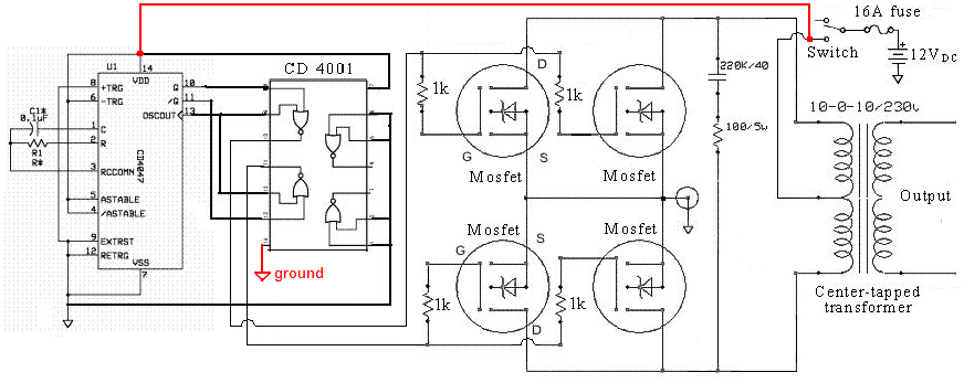
Just to clarify something, the resistor value that was input to CD4047, can i use a potentiometer instead of fixed value so as i can adjust the frequency accordingly? Furthermore, can i used a 9-0-9/230 with a rated of 36VA instead of 10-0-10/230 transformer. What will be the difference and if not, can i use a 12-0-12/230 transformer? Lastly, there is a capacitor that is connected in series to a resistor of 100/5W. What is the value of the capacitor, is it 220uF and also is it a AC or DC capacitor?
Anyway, thanks for your kindly response.
Download Attachment:  20081910308_Modified sine-wave inverter schematic.png 20081910308_Modified sine-wave inverter schematic.png
109.42 KB
|
|
|
|
eng.zahir
Apprentece
Bangladesh
7 Posts |
Posted - May 04 2008 : 11:20:42 AM

|
| Hi audioguru pls tell me wts the work of pin13 of CD4047? |
|
|
|
audioguru
Nobel Prize Winner
Canada
4218 Posts |
Posted - May 04 2008 : 9:38:48 PM
|
Pin 13 of a CD4047 is explained in its datasheet.
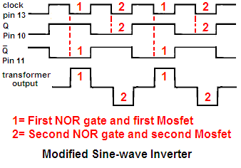
It is its 100Hz oscillator output in the inverter which is an output in the IC before the digital frequency divider in it provides the 50Hz outputs at pin 10 and 50Hz inverted output at pin 11.
Look at my sketch to see how the logic makes the signals for the Mosfets:
Download Attachment: Modified inverter logic.PNG
8.26 KB
 |
|
|
|
eng.zahir
Apprentece
Bangladesh
7 Posts |
Posted - May 05 2008 : 01:05:16 AM
|
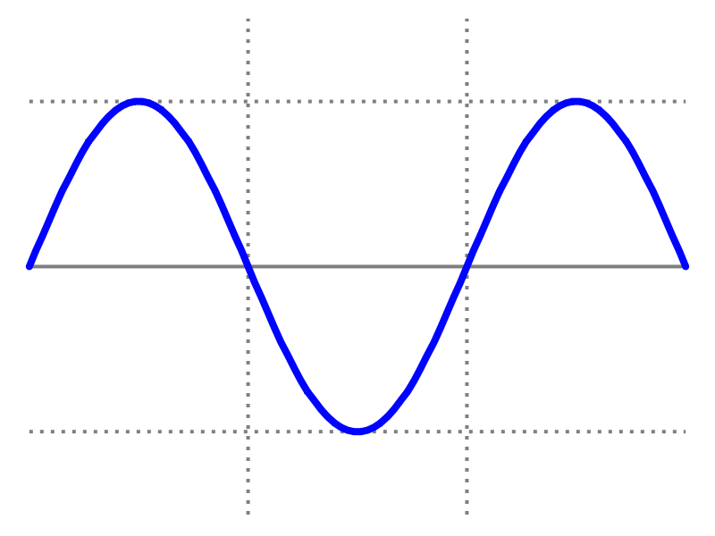
Hi audioguru this is square wave but i need sine wave
Download Attachment: sine_wave.png
19.4 KB
 |
|
|
|
akagi
New Member
2 Posts |
Posted - May 05 2008 : 06:08:45 AM
|
Hi,
in order to have a sine wave, a low pass filter must be integrated to the circuit so as to remove away the odd harmonics. I would like to know the purpose for the circuit on the top left hand corner, the zener, the cap and the resistor. Can someone assist me? |
|
|
|
akagi
New Member
2 Posts |
Posted - May 05 2008 : 06:27:48 AM
|
| another thing is why is there a need for resistors to be present before the gates of the mosfets? is it for reducing the current flowing into the mosfets so as to prevent these power semiconductor switches from drawing high current? |
|
|
|
audioguru
Nobel Prize Winner
Canada
4218 Posts |
Posted - May 05 2008 : 10:31:33 AM
|
A sine-wave has a peak voltage that is 1.414 times the peak voltage of a auare-wave. So a different transformer is used.
A high current filter to convert a 50Hz square-wave to a 50Hz sine-wave will be huge and will have such a high resistance that very low power will be at its output. Most of the power from the inverter will heat the inductor.
A "pure-sine-wave" inverter uses a complicated Pulse-Width-Modulation circuit that operates at a high frequency so its filter parts are small and work properly.
The zener diode and resistor are used to eliminate voltage spikes that will kill the Cmos IC. The capacitor is needed for any electronic circuit.
All Mosfet circuits use a low value resistor in series with each gate close to the Mosfet (some use a ferrite bead) to prevent the Mosfet from oscillating at a VHF or UHF frequency. It will get extremely hot if it oscillates.
A Mosfet does not have input current. A current is needed at its input to quickly charge and discharge its high input capacitance. |
|
|
|
eng.zahir
Apprentece
Bangladesh
7 Posts |
Posted - May 07 2008 : 08:14:21 AM
|
| pls any one give me a pure sine wave (50Hz) inverter circuit diagram. PLSSSSSSSSSSSSSSSSSSSSSSSSSSSSSSSSSSSSSS |
|
|
|
Topic |
|