| Home > RX-7 > Tech/Mods > Mods > Megasquirt > Programming The ECU (MS2) |
| Home > RX-7 > Tech/Mods > Mods > Megasquirt > Programming The ECU (MS2) |
This section covers programming the MS2 ECU to run the 13B rotary. Because there is such a difference between the setup of the various MegaSquirt versions, each ECU has it's own configuration page. Make sure you are reading the correct page for your ECU version.
If you have not already done so using a Stimulator during the build/modding section the first step is to flash the appropriate firmware into the Megasquirt. For convenience I've reproduced those instructions here.
The stock Bowling & Grippo firmware loaded onto Megasquirt CPUs from the factory will run the rotary, but it will run fuel only and without a lot of the features we depend on (such as staged injection). It is therefore necessary to load the Megasquirt and Spark Extra (MSnSE) firmware.
Disconnect the ignition coils from the harness before proceeding! Failure to do this will burn out the coils!
Plug the computer into the Megasquirt. For MSII users,see the MS2-Extra Software Manual for installation instructions for the latest version of MS2/Extra.
Don't bother following the instructions on the above websites to configure the Megasquirt to your engine. We'll do that later.
At this point, if you have not already downloaded TunerStudio MS, do so now and install it. The free version will suffice for now however you may want to upgrade to the paid version when you start tuning as only the paid version can autotune the VE table.
Power up your Megasquirt and make sure that it is responding to inputs. The first time you run TunerStudio you will need to create a project for your ECU. DIYAutoTune has some great generic TunerStudio setup instructions.
Note that when you are configuring TunerStudio, you need to select the appropriate Lambda Sensor and Idle Controller. Set LAMBDA_SENSOR to "AEM_LINEAR -- AEM Gauge AEM-30-42xx" and IDLE_CONTROLLER to "PWM_GAUGE -- PWM Idle Valve (e.g., Ford or Bosch)".
Basic parameters need to be set up in the ECU to tell it the displacement of the engine, how many injectors it has, the trigger and ignition setup and what to do with it's outputs. The MS2 firmware is still being developed (unlike MS1 which is basically done) so it is possible that some of the screens you see here may not exactly match the firmware you are running. Each settings page will be shown with a chart of the settings, and a screenshot of what they look like. Any settings that are not mentioned can just be left default. Keep in mind that you don't have to be connected to the ECU to make these settings. But do not start with a blank map! Open up TunerStudio and connect to your ECU to download all the settings. Then save an MSQ. You can work on this MSQ offline if you find it more convenient than sitting in the car typing in settings. You can then load that MSQ into the ECU when you are in the car. If you are programming the ECU live, make sure to press "Burn To ECU" before closing each window. Otherwise the changes are made to the map in TunerStudio but not sent to the ECU.
I am not going to explain in detail every setting on this page. To do so would be a monumental task and simply repeat information in the Megasquirt manuals. With each screen I will give you the basic idea of what the settings do but if you want to know more, it is up to you to look it up.
The settings are presented below in a list with the title of each item representing the menu choices needed to open up those settings. We start with the most basic characteristics of the engine.
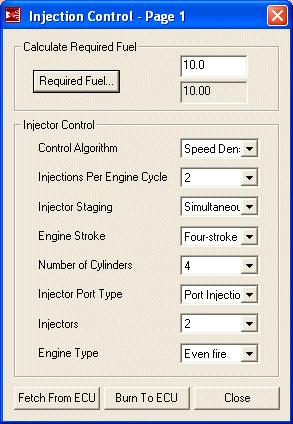
These settings are the basic characteristics of the engine. Note that the number of injectors is set to two. This is correct, because even though we have 4, the secondaries are staged and not always operating.
|
|
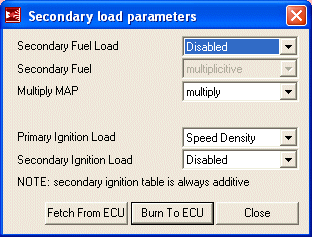
More engine constants allows you to set up multiple methods of determining engine load. For example, you could run Alpha-N (TPS vs. RPM) if you have a weak vacuum signal. For the stock rotary, we only need speed density of as our control method so secondary methods can be disabled.
|
|
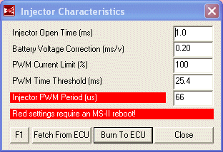
These settings tell the Megasquirt how to control the injectors. The settings presented here are for high impedance injectors. For low impedance injectors, the PWM Current Limit and PWM Time Threshold settings need to be tuned however I have found that because only two injectors per driver circuit are used on the rotary, these settings seem to work fine for both high and low impedance injectors with no damage to the injectors or the Megasquirt.
|
|
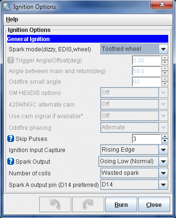
These settings tell the Megasquirt where it is getting an RPM signal (toothed wheel) and how to use that signal. They also tell the Megasquirt how to fire the ignition coils (bring the output low) and that the engine is going to be firing both leadings on one coil (wasted spark).
|
|
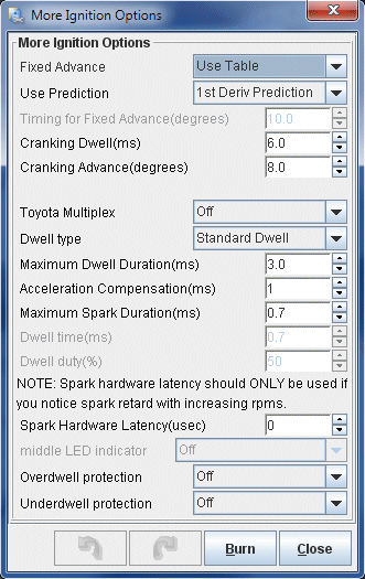
The aptly named "More Ignition Settings" menu contains, surprisingly, more ignition settings. These are the secondary settings such as where to pull timing from, dwells and rotary mode. For now, ignition advance should come from the main timing table but during the initial startup we will revisit this screen and set a fixed advance so the CAS position can be adjusted.
|
|
You probably won't have to change any of these options past the initial setup. One which might end up getting tweaked is "Cranking Advance". 8 degrees may be too much in some applications and can cause the engine to kick back against the starter. I have found that in stock port setups, around 8 degrees provides a very snappy startup.
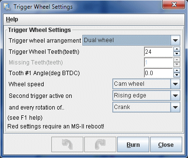
We already told the Megasquirt that it is getting its tach input from a trigger wheel, so now it needs to be told how to read the pulses coming from that wheel. Once these options are set, they will not have to be readjusted.
|
|
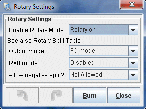
The "Rotary Settings" dialog defines some rotary specific ignition settings. There are only a few options here. Output mode gets set to use FC coils (wasted spark leading and individual toggle-style trailing). Negative split is set to disabled for now but this is an option you may wish to explore later. Using negative split (firing trailing before leading) at idle and light load can result in emissions and fuel economy increases.
|
|
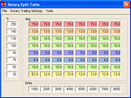
The trailing settings specify how many degrees after the leadings the trailing plugs fire. This is referred to as "split". The table presented here is safe and efficient for both turbo and NA cars. As tuning split is a bit of a black art and rather hotly debated, leave this table alone unless you have an idea of what you are doing. The one thing you may want to do is dial in a few more degrees of split under boost for a bit more safety. Though 10 degrees is safe, many tuners run around 15 degrees.
|
Thankfully, TunerStudio doesn't require you to type that mess into the table manually. Tables can be imported and exported. Below is a link to this table TunerStudio's table exchange .VEX format. To import it, download the file and then from the Rotary Split Table dialog, select "File" and then "Table Import...". Browse to the downloaded file and open it up to start the import. This is a table for a 13B turbo engine but will work equally well for an NA. If tuning an NA, all the bins above 100% can be discarded and that side of the table rescaled with more resolution available from 0-110% or so. Set your last bin to 110% because atmospheric pressure varies. |
|
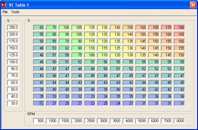
The VE (volumetric efficiency) table represents the main fuel map for the engine and is where you will be doing most of your tuning. Each engine combination is going to need a wildly different VE table and even two engines configured exactly the same will end up with a different table when tuned. Therefore, this table is only suited as a first startup and limp to the dyno map. It should start the car and run it reasonably well but is by far not ideal for your engine. It will give you a good place to start tuning. Do not just load this table, start the car and run the engine into boost. While this table should be safely rich everywhere, there is no guarantee. Carefully approach boost and judge for your self how much you have to richen up that area of the map before getting throttle happy.
|
Thankfully, TunerStudio doesn't require you to type that mess into the table manually. Tables can be imported and exported. Below is a link to this table TunerStudio's table exchange .VEX format. To import it, download the file and then from the VE Table 1 dialog, select "File" and then "Table Import...". Browse to the downloaded file and open it up to start the import. This is a table for a 13B turbo engine but will work equally well for an NA. If tuning an NA, all the bins above 100% can be discarded and that side of the table rescaled with more resolution available from 0-110% or so. Set your last bin to 110% because atmospheric pressure varies. |
|
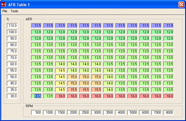
The AFR table provides air/fuel ratio targets for the Megasquirt to follow when operating under closed loop. With a wideband sensor the Megasquirt is able to work to achieve a variety of AFRs, not just 14.7 as it would with a narrowband. The ratios presented in this table are a very good starting point. It is really only the cruise area we are concerned with (the area showing AFRs of around 15:1) as the Megasquirt is set to go open-loop everywhere else.
|
Thankfully, TunerStudio doesn't require you to type that mess into the table manually. Tables can be imported and exported. Below is a link to this table TunerStudio's table exchange .VEX format. To import it, download the file and then from the AFR Table 1 dialog, select "File" and then "Table Import...". Browse to the downloaded file and open it up to start the import. This is a table is a good start for both NA and turbo 13Bs. |
|
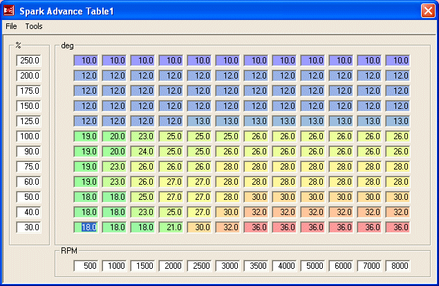
This is the main timing table referenced anytime the engine is running. The only period during which this table is not used is when the engine is cranking. This table should run most rotary engines quite well and you will probably only have to make minor adjustments. It is safe to run in boost as well as in NA applications.
|
Thankfully, TunerStudio doesn't require you to type that mess into the table manually. Tables can be imported and exported. Below is a link to this table TunerStudio's table exchange .VEX format. To import it, download the file and then from the Spark Table 1 dialog, select "File" and then "Table Import...". Browse to the downloaded file and open it up to start the import. This is a table for a 13B turbo engine but will work equally well for an NA. If tuning an NA, all the bins above 100% can be discarded and that side of the table rescaled with more resolution available from 0-110% or so. Set your last bin to 110% because atmospheric pressure varies. |
|
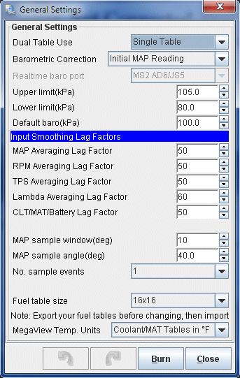
The general settings tell the Megasquirt whether to operate in single or dual table mode, how to correct for differences in atmospheric pressure and what kind of acceleration enrichment to use. We are only operating in single table mode. As for the lag factors, they tell the Megasquirt how log it takes each sensor to register a reading the time whatever it is measuring has changed. These can be left as default unless you experience issues (such as jittery sensor readings not caused by bad grounding).
|
|
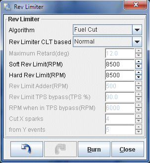
There are several rev limiter options available but here we are using fuel cut. Since all fuel is cut, there is no risk in running lean as there would be with a partial fuel cut. However if you are constantly bouncing off the rev limiter it will pay to set up a hard and soft limit by cutting spark as this will result in a much smoother feel.
|
|
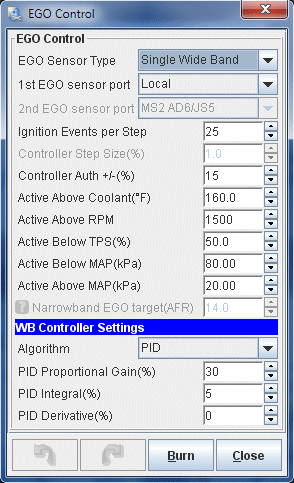
These settings define how the oxygen sensor (wideband) is used. We set the EGO Sensor Type to "Wide band" which is installed on the Normal EGO port (pink wire) and applies to all injectors as the rotary doesn't have "banks" like a V piston engine. The algorithm that is used to control the AFR mixture from wideband feedback is the PID algorithm, which adjusts its response based on how far out the input is from the desired output. It makes these adjustments every 25 ignition events (Ignition Events per Step) with a maximum change of 15% (Controller Auth) and is active above AFR 9.0:1 (Only correct above) but below 20:1 (and correct below). The next bunch of settings set some parameters as to when closed loop is entered regarding minimum coolant temp, maximum TPS (throttle) value, maximum engine load (as on the left side of the VE table), etc. Most of these can be left alone for most cars however some might need to be tweaked. Radical porting will mean vacuum is low so the load value may need to be increased. S4 cars with narrow range TPSs may need to increase the TPS percent as those TPSs go to 100% at 1/4 throttle. In that case, both TPS and Load should be used to define closed loop. Finally, at the bottom are the actual PID algorithm parameters; the proportional gain, integral and derivative. The values I have supplied should result in smooth control in 99% of applications. But if you need to adjust, read the MS3 documentation (yes, MS3 as it has a better explanation) first.
|
|
Once you have made the changes in EGO Control, go back and set the "Controller Authority" to 0 (zero) to disable closed loop operation. During the first startup and initial tuning, closed loop will get in the way so it is best to turn it off. Once you have your VE table reasonably well set, you can go back to these settings and set it to 15%.
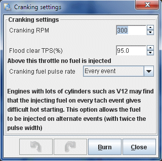
These settings define parameters used during cranking and startup. For example, the "Cranking RPM" defines the engine speed below which the engine is considered to be cranking. "Flood clear TPS (%)" sets the TPS value above which the injectors are disabled during cranking. This is very useful to clear a flooded engine by simply flooring the pedal and cranking the car. The rest of the settings aren't really anything which will have to be changed for our setup.
|
|
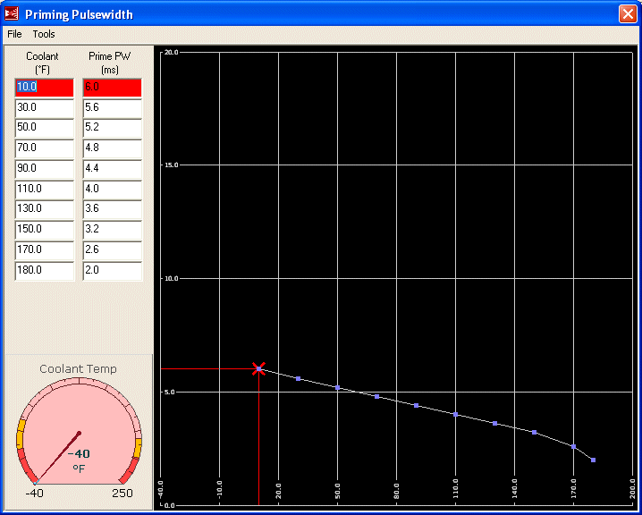
The priming pulse is the initial injector opening time which occurs just after the Megasquirt is powered on. It is there to "prime" the injectors with fuel and to set up a slight vapour cloud in the intake ports to help with starting. These numbers are not really critical as long as they are in the ballpark so it's unlikely you will be spending much time tuning them. The table presented here will work for most setups. Of far more importance is the cranking table which will be covered next.
|
|
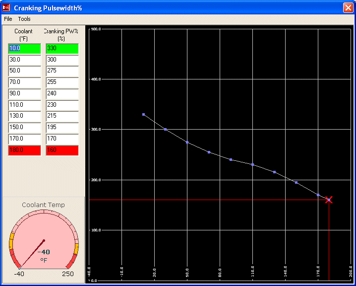
The cranking pulse tells the Megasquirt how much to enrich the fuel mixture while the engine is cranking. Unlike the MS1 where this is specified as a fixed pulsewidth, the MS2 specifies it as a percentage of the main fuel map. Thus your final settings will depend on your VE table. These settings should get you going but should be considered quite rich.
|
|
After Start Enrichment (ASE) increases fuel supply to the engine just after starting, for a specified number of engine cycles. This helps with both a hot start condition (heat soaked) and a cold start condition (fuel tends to collect on the intake runners) as the engine typically runs lean for a few seconds directly after startup. However during the initial tuning, this can often confuse things. The engine may attempt to stall which will trigger the ASE, which will cause it to run unevenly then attempt to stall again, triggering the ASE. This can be very irritating. For now I suggest you disable ASE by setting all of the "Afterstart (%)" bins in this window to 0. Once some tuning on the car has been done and it is starting reliably, then ASE can be revisited.
ASE Taper is the number of engine cycles that ASE is applied. As ASE has been effectively disabled in the previous step then whatever is in this table is irrelevant. However in the beginning, when starting to tune ASE, it helps to set all of these bins to a fixed amount. So if you wish you can take this opportunity to set all of the "Taper (cycles)" bins to "250".
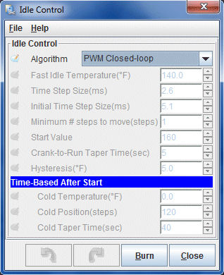
There is only one setting in Idle Control that we need to configure. Once it is selected, all other options are disabled. Set "Algorithm" to "PWM Closed Loop".
|
|
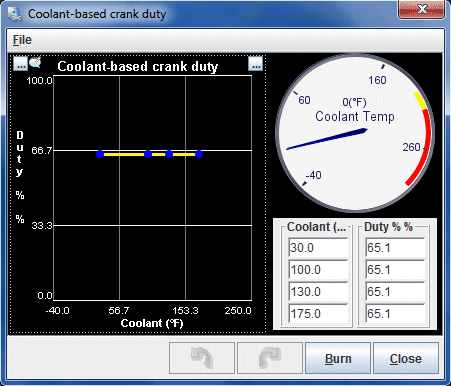
PWM idle cranking duty sets the duty cycle (opening amount) of the idle valve during cranking. This is based on the temperature of the coolant. Opening up the idle valve a little during cranking lets a bit more air into the engine and basically simulates the old school technique of a little bit of throttle while cranking. You may find that cooler temperatures need more idle valve during cranking to prevent a stall after starting, operating temperature requires less, while heat soak once again can benefit from more air. For now everything is set to 65% which will suit most cases without causing the engine RPM to spike after starting.
|
|
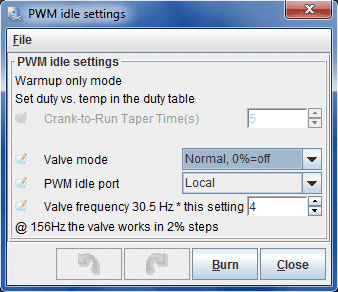
These settings tell the Megasquirt the basics of how to operate the BAC. The Valve mode is set to normal, meaning that more PWM opens up the valve farther. The PWM idle port is the on-board "Fidle" or "Local" port. Finally, the frequency setting is set to 4 x 30.5Hz for a PWM frequency of 122Hz.
|
|
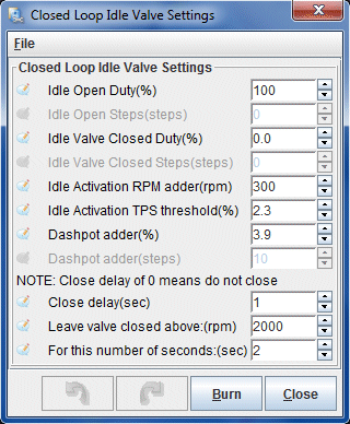
There are a lot of closed loop idle settings because getting a stable idle control involves a lot of different factors. I'll give some basic explanation here however if you want the full details you should see the idle control documentation in the MS3 software manual. Even though you are programming an MS2, the MS3 documentation on PWM idle control is far more up to date. Many of the settings overlap and effect one another. Idle open and closed duty reflect the duty cycles where the valve is fully open and fully close. Note that these can be adjusted to limit the operational range of the valve. Idle Activation TPS and RPM thresholds define when we enter PWM idle control. Dashpot adder is the percentage of duty cycle added briefly to the valve as the engine RPM drops. This prevents RPM from plummeting below idle and stalling the engine. The dashpot duty is reduced over the decay factor. The next three settings configure how the valve is closed once the throttle is opened again. The valve doesn't need to be open as the RPM increases to after 2000 RPM, the valve is left closed.
|
|
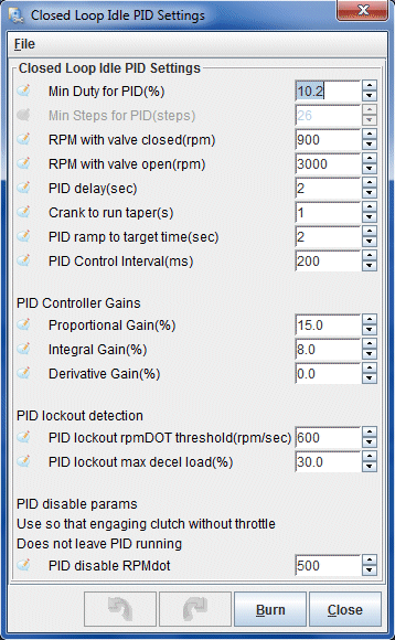
The closed loop idle PID settings define how the PID algorithm will control the idle. The minimum closed loop duty is set (min duty for PID). Below that we tell the algorithm the idle RPM if the valve is fully closed (the idle RPM set by the hard idle stop screw) and the RPM with the valve fully open. Note that the 2nd gen BAC can produce about 4000 RPM when fully open but we set this a little low to increase the sensitivity of the algorithm. We next have a set of delays relating to how long to wait to enter PID idle control, and below that the control interval. The PID Control Interval sets how often the PID control loop runs. Below that we have the main PID loop settings which define how the PID algorithm actually seeks the desired idle. Details to set this are in the MS3 documentation.
|
|
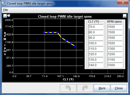
This curve sets the idle speed, according to temperature, that the PID idle control algorithm will seek. This allows a higher idle when cold (when fuel atomization is poor, the alternator is refilling the battery after cranking, and we want the engine to heat up to operating temperature quickly) which will gradually taper down to a lower final idle speed as the engine reaches operating temperature. This is especially important if the vehicle has catalytic converters as the higher exhaust temps created by higher engine speed will light them off quickly, dramatically reducing cold start emissions.
|
|
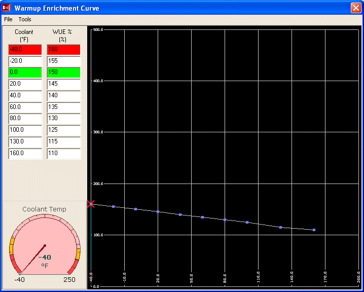
Warmup enrichment increases fuel supply to the engine while it is warming up. This is necessary because fuel atomizes less efficiently and tends to cling to runner walls when the engine is cold. These numbers, like the cranking table, depend on the main VE table so don't spend much time here until the VE table is workable.
|
|
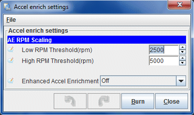
The basic acceleration enrichment settings simply define which method of accel enrichment is used. For now, the ECU is just set to basic "accelerator pump" enrichment by turning "Enhanced Accel Enrichment" off. The two RPM thresholds define how the accel enrichment is scaled with RPM. Defaults are typically fine.
|
|
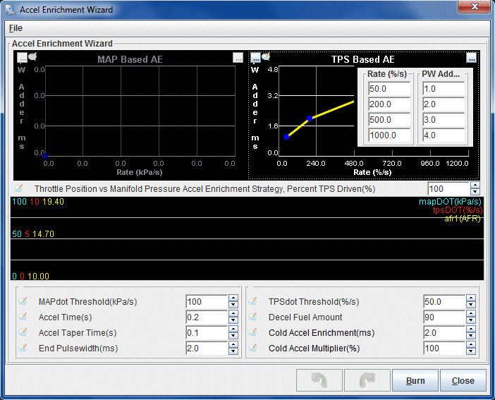
These curves set the amount of fuel added by the accel pump when the throttle is pressed down. This is expressed by percentage of the VE table over TPSdot. That is, the quicker the TPS voltage increases over a period of one second, the more fuel that is injected during that movement. These are basic settings which suit a full range TPS. The problem is, S4 cars have a 1/4 range TPS which is reading 100% at about 1/4 throttle. In this case, the best method for accel enrichment would be to blend MAPdot and TPSdot. But give these settings a try. You may find that by simply decreasing the fuel addition at the top of TPS range, TPSdot works pretty well. These are mostly default settings as the accel pump can't really be tuned very well until the VE table is close to fully tuned.
|
|
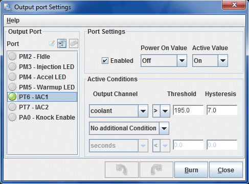
The Megasquirt has several outputs that are configurable to operate under a variety of conditions. The only one we are already using is FIDLE, for the BAC valve which leaves a bunch free. One of the IAC (idle stepper motor) control ports will be used to control the e-fan, which gets set up in this screen.
|
|
The "Threshold" is the value of the variable (in this case coolant) at which you want the output to trigger. "Hysteresis" is the changed required to turn that output off. Therefore, in these settings, the fan comes on at 195 degrees and switches off at 188 degrees. These switching temperatures work well in combination with the stock thermostat. The fan will cycle on and off during low speed driving, and remain totally off when there is enough airflow through the rad to keep the car cool.
Barometric correction will correct the reading of the MAP sensor for various atmospheric pressures. At the moment it is not necessary so just leave the settings at their defaults of all zeros. It really only is necessary if you are driving in an area where the pressure swings significantly, for example, in the mountains.
Cold advance allows you to add or remove timing based upon coolant temperature. This is most useful when a little bit more timing is necessary as the engine warms up to maintain smoothness. For now and during the initial tune, it won't be helpful. Only after all other major fuel and ignition tuning has taken place should these settings be used.
Manifold air temperature timing retard allows you to pull timing at high manifold temperatures. For the moment, just leave these settings at the default. Note: If you have high IATs and/or a stock top mount intercooler, you will probably want to tune this later. MAT ignition retard will allow you to pull timing if you are experiencing high intake temps that may be caused by an inefficient (like the stock) turbo and/or a stock top mount intercooler. If you are running more then 15 degrees of timing under boost and experiencing high intake temps you will want to start pulling out timing to avoid detonation.
MAT Correction allows you to fine tune the air density calculation as performed by the ECU relating to air temperature. You can use this to compensate for heat soak conditions or poorly placed IAT sensors. For the initial tune, this should be left at the default of zero across the board.
Unless you actually have a GM style Flex Fuel sensor installed, then set "Flex Fuel Sensor" to "Disabled". This is only used in flex fuel applications (E85) and even if you have such a thing installed on your RX-7, it is not covered in this writeup.
As there is no knock sensor installed, these settings can be left at defaults. They will not effect the operation or turning of the engine.
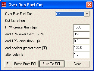
The over run settings tell the Megasquirt when fuel should be cut during over run (decel). With the TPS and manifold pressure below a certain threshold (set in this window) the Megasquirt knows the car is decelerating and will cut all fuel to prevent bucking, save fuel and stop from suffocating those drivers behind you. The settings I have provided here are probably going to be good for almost everyone. One thing you may want to increase is the RPM setting if you have a habit of engine braking to the very last second.
|
|
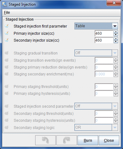
To properly run the RX-7s staged injection, the Megasquirt needs to be set up with the size of the staged injectors and when to actually stage them. This is done in the appropriately named "Staged Injection" window. There are few options to set because the smoothest staging method is "Table", which is being used here. All other options become disabled at this point save for the actual injector sizes. Note that this window shows 460CC injectors as installed in a stock NA. If your car is a TII, then you have 550CC injectors. Obviously, if you are running a different injector combination these settings should be altered to reflect that.
|
|
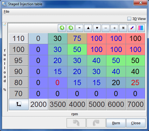
This table, referenced by RPM and load points, define how the secondary injectors are blended into the fuel amount being injected into the engine. You'll notice the table jumps directly from 0 to some value. This is to prevent the secondary pulsewidth from starting too low in the unstable region. For most cars with equal primaries and secondaries this table will result in a smooth transition. But if you have much larger secondaries than primaries, you may need to reduce the amount of secondary injector or scale the entire table up so more if it is within positive manifold pressure.
|
Thankfully, TunerStudio doesn't require you to type that mess into the table manually. Tables can be imported and exported. Below is a link to this table TunerStudio's table exchange .VEX format. To import it, download and unzip the file. From the Staged Injection table window, right click the table and select "Import Table". Browse to the downloaded file and open it up to start the import.
|
|
The dash tach is triggered by the trailing coil so it's unnecessary for the Megasquirt to operate it. Disable tachometer output by setting "Tacho output enabled" to "Off", which is the default setting.
Disable launch control by setting "Launch control option" to "Off", which is the default setting. There is no need to have launch control enabled at this point or during tuning. If you wish to experiment with it later then do so only after the engine is fully tuned.
Dwell is already setup in "More Ignition Settings". This screen allows you to compensate for battery voltage changes by increasing or lowering dwell. For the time being, leave it at the defaults. It is unlikely you will have to change any of these options.
Set "False trigger method" to "Simple", which is the default and will disable all other options in this dialog box.
You can ignore this menu option unless you already know what it means.
You can ignore this menu option unless you already know what it means.
The noise filter can help filter out ignition trigger noise by telling the ECU to ignore pulses of too low a duration at various RPM points. Leave this at the defaults for now but if you are experiencing noise that you cannot solve by fixing the hardware, you may need to tune the noise filter.
You're probably now asking yourself why I didn't just provide a base map that you can load into the ECU with all of those settings already in place. Well, what would you have learned then? If I had just provided a base map without explaining the key settings then you would have no basis of knowledge for possible troubleshooting.
Now that you've spend the better part of an hour entering those settings, it is time to power prepare the Megasquirt for first startup by setting the TPS and telling the Megasquirt how to interpret the wideband signal.
Before we can start the car, the Megasquirt needs to know what value on the TPS represents closed throttle and what value represents wide open throttle.
With the laptop connected, power on the car but do not attempt to start it. If you entered the map correctly the fuel pump should prime for a few seconds and then shut off. All the gauges in TunerStudio should come to life. The water temp and intake temp gauge should show ambient temperatures if the car is at room temperature.
From the from the "Tools" menu, select "Calibrate TPS..." to show the following screen:
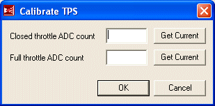
With the throttle fully closed, press the top "Get Current" button. A number will now show up beside "Closed throttle ADC count".
Now floor the throttle and press the bottom "Get Current" button. A number will now show up beside "Full throttle ADC count". If this number is smaller then "Closed throttle ADC count", your TPS is connected backwards.
Click the OK button. Thus ends the TPS calibration.
The wideband outputs a voltage corresponding to the air fuel ratio it is reading. Not every wideband outputs the same voltage per AFR so the Megasquirt must be calibrated so that the AFR tables accurately represent wideband output. From the "Tools" menu, select "Calibrate AFR Table..." to show the following calibration screen:
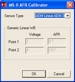
For "Sensor Type" select "AEM Linear AEM-30-4200" and then hit "OK". The processor will be programmed with the calibration table for that sensor.
When complete, power cycle the processor.
It's all been building to this and now the time has come. The next section of this writeup covers how to start the car, set the base timing and get something resembling an idle.
Back To Mods Page | Mail Me | Search | ![]()